EP1286771B1 - Chambre de microhybridation - Google Patents
Chambre de microhybridation Download PDFInfo
- Publication number
- EP1286771B1 EP1286771B1 EP01927767A EP01927767A EP1286771B1 EP 1286771 B1 EP1286771 B1 EP 1286771B1 EP 01927767 A EP01927767 A EP 01927767A EP 01927767 A EP01927767 A EP 01927767A EP 1286771 B1 EP1286771 B1 EP 1286771B1
- Authority
- EP
- European Patent Office
- Prior art keywords
- sample chamber
- sample
- spacer
- plates
- support
- Prior art date
- Legal status (The legal status is an assumption and is not a legal conclusion. Google has not performed a legal analysis and makes no representation as to the accuracy of the status listed.)
- Expired - Lifetime
Links
Images

Classifications
-
- B—PERFORMING OPERATIONS; TRANSPORTING
- B01—PHYSICAL OR CHEMICAL PROCESSES OR APPARATUS IN GENERAL
- B01L—CHEMICAL OR PHYSICAL LABORATORY APPARATUS FOR GENERAL USE
- B01L3/00—Containers or dishes for laboratory use, e.g. laboratory glassware; Droppers
- B01L3/50—Containers for the purpose of retaining a material to be analysed, e.g. test tubes
- B01L3/508—Containers for the purpose of retaining a material to be analysed, e.g. test tubes rigid containers not provided for above
-
- B—PERFORMING OPERATIONS; TRANSPORTING
- B01—PHYSICAL OR CHEMICAL PROCESSES OR APPARATUS IN GENERAL
- B01L—CHEMICAL OR PHYSICAL LABORATORY APPARATUS FOR GENERAL USE
- B01L9/00—Supporting devices; Holding devices
- B01L9/52—Supports specially adapted for flat sample carriers, e.g. for plates, slides, chips
-
- B—PERFORMING OPERATIONS; TRANSPORTING
- B01—PHYSICAL OR CHEMICAL PROCESSES OR APPARATUS IN GENERAL
- B01L—CHEMICAL OR PHYSICAL LABORATORY APPARATUS FOR GENERAL USE
- B01L2200/00—Solutions for specific problems relating to chemical or physical laboratory apparatus
- B01L2200/02—Adapting objects or devices to another
- B01L2200/026—Fluid interfacing between devices or objects, e.g. connectors, inlet details
-
- B—PERFORMING OPERATIONS; TRANSPORTING
- B01—PHYSICAL OR CHEMICAL PROCESSES OR APPARATUS IN GENERAL
- B01L—CHEMICAL OR PHYSICAL LABORATORY APPARATUS FOR GENERAL USE
- B01L2200/00—Solutions for specific problems relating to chemical or physical laboratory apparatus
- B01L2200/06—Fluid handling related problems
- B01L2200/0689—Sealing
-
- B—PERFORMING OPERATIONS; TRANSPORTING
- B01—PHYSICAL OR CHEMICAL PROCESSES OR APPARATUS IN GENERAL
- B01L—CHEMICAL OR PHYSICAL LABORATORY APPARATUS FOR GENERAL USE
- B01L2300/00—Additional constructional details
- B01L2300/06—Auxiliary integrated devices, integrated components
- B01L2300/0627—Sensor or part of a sensor is integrated
- B01L2300/0636—Integrated biosensor, microarrays
-
- B—PERFORMING OPERATIONS; TRANSPORTING
- B01—PHYSICAL OR CHEMICAL PROCESSES OR APPARATUS IN GENERAL
- B01L—CHEMICAL OR PHYSICAL LABORATORY APPARATUS FOR GENERAL USE
- B01L2300/00—Additional constructional details
- B01L2300/08—Geometry, shape and general structure
- B01L2300/0809—Geometry, shape and general structure rectangular shaped
- B01L2300/0822—Slides
-
- B—PERFORMING OPERATIONS; TRANSPORTING
- B01—PHYSICAL OR CHEMICAL PROCESSES OR APPARATUS IN GENERAL
- B01L—CHEMICAL OR PHYSICAL LABORATORY APPARATUS FOR GENERAL USE
- B01L2300/00—Additional constructional details
- B01L2300/08—Geometry, shape and general structure
- B01L2300/0861—Configuration of multiple channels and/or chambers in a single devices
- B01L2300/0877—Flow chambers
-
- B—PERFORMING OPERATIONS; TRANSPORTING
- B01—PHYSICAL OR CHEMICAL PROCESSES OR APPARATUS IN GENERAL
- B01L—CHEMICAL OR PHYSICAL LABORATORY APPARATUS FOR GENERAL USE
- B01L2300/00—Additional constructional details
- B01L2300/18—Means for temperature control
-
- B—PERFORMING OPERATIONS; TRANSPORTING
- B01—PHYSICAL OR CHEMICAL PROCESSES OR APPARATUS IN GENERAL
- B01L—CHEMICAL OR PHYSICAL LABORATORY APPARATUS FOR GENERAL USE
- B01L7/00—Heating or cooling apparatus; Heat insulating devices
- B01L7/52—Heating or cooling apparatus; Heat insulating devices with provision for submitting samples to a predetermined sequence of different temperatures, e.g. for treating nucleic acid samples
- B01L7/525—Heating or cooling apparatus; Heat insulating devices with provision for submitting samples to a predetermined sequence of different temperatures, e.g. for treating nucleic acid samples with physical movement of samples between temperature zones
-
- G—PHYSICS
- G01—MEASURING; TESTING
- G01N—INVESTIGATING OR ANALYSING MATERIALS BY DETERMINING THEIR CHEMICAL OR PHYSICAL PROPERTIES
- G01N35/00—Automatic analysis not limited to methods or materials provided for in any single one of groups G01N1/00 - G01N33/00; Handling materials therefor
- G01N35/00029—Automatic analysis not limited to methods or materials provided for in any single one of groups G01N1/00 - G01N33/00; Handling materials therefor provided with flat sample substrates, e.g. slides
- G01N2035/00099—Characterised by type of test elements
- G01N2035/00158—Elements containing microarrays, i.e. "biochip"
-
- G—PHYSICS
- G01—MEASURING; TESTING
- G01N—INVESTIGATING OR ANALYSING MATERIALS BY DETERMINING THEIR CHEMICAL OR PHYSICAL PROPERTIES
- G01N35/00—Automatic analysis not limited to methods or materials provided for in any single one of groups G01N1/00 - G01N33/00; Handling materials therefor
- G01N2035/00465—Separating and mixing arrangements
- G01N2035/00475—Filters
- G01N2035/00485—Filters combined with sample carriers
-
- G—PHYSICS
- G01—MEASURING; TESTING
- G01N—INVESTIGATING OR ANALYSING MATERIALS BY DETERMINING THEIR CHEMICAL OR PHYSICAL PROPERTIES
- G01N35/00—Automatic analysis not limited to methods or materials provided for in any single one of groups G01N1/00 - G01N33/00; Handling materials therefor
- G01N35/00584—Control arrangements for automatic analysers
- G01N2035/0097—Control arrangements for automatic analysers monitoring reactions as a function of time
Definitions
- the invention generally relates to a sample chamber for the liquid treatment of at least one sample, in particular a sample chamber for fluid treatment of a plurality of samples, such.
- DNA chips In genetic engineering and biochemistry, it is generally known to examine samples of genetic materials with so-called DNA chips. Several thousand microscopically small samples are arrayed on a carrier plate on a DNA chip.
- the samples contain the biomolecules to be investigated, for example DNA, RNA, proteins or antibodies.
- the samples may already be marked, if later z. B. to be detected after a reaction or otherwise change with optical methods. Common detection methods are measurements of fluorescence, chemiluminescence or radioactivity. For other detection methods, such. As mass spectrometry, absorption measurements, or adsorption measurements, the sample molecules may also be unlabeled.
- the target molecule assembly on the support plate is overlaid with a test solution containing the sample molecules. Upon hybridization of certain sample molecules from the test solution to the target molecules immobilized on the support plate, a signal can be measured at the corresponding target molecules, which is typically a fluorescence signal.
- the carrier plate for example, loaded with a picking / spotting robot, was overlaid with the test solution and the test solution was covered with a cover glass.
- the cover glass as it is, for example, from microscopy is known, is a platelet with a thickness as small as possible, which floats on the test solution and is held over the surface tension on the support plate at a distance from the samples.
- This conventional technique of combining a backing plate with a thin coverslip has the advantage of low assay solution usage in the range of 10 ⁇ l to 20 ⁇ l per chip. But it also has the important disadvantages explained below.
- Sample throughput on a DNA chip has hitherto been limited by the sample density achievable with the robots currently in use.
- sample density achievable with the robots currently in use.
- sample throughput number of samples treated or used per experiment or per unit of line.
- Another disadvantage is that a composite of loaded carrier plate, over-coated test solution and cover glass is difficult to handle. An automated manipulation of the overall structure, eg. B. for a reproducible and uniform supply of the test solution is excluded.
- layered cuvettes which form closed sample chambers and are designed especially for optical measurements through the cuvettes.
- cuvettes have the advantage of high stability and correspondingly good handling.
- their use as a DNA chip is ruled out because the inner cuvette walls are not designed for sample placement with the commonly used spotting technique.
- the patent application WO 97/45730 A discloses a device with two plane-parallel glass plates, both of which are provided with samples or reagent matrices.
- U.S. Patent US-A-5,352,609 discloses an insert cassette for working out purified nucleic acids from cells comprising a dialysis chamber and a filter in the dialysis chamber.
- US Pat. No. 4,010,554 describes an apparatus for the preparation and visual presentation of organ samples in the form of anatomical sections.
- the organ samples are placed between two cover plates with which a liquid-tight chamber is formed.
- the sample chamber should also enable safe handling of radioactively labeled sample solutions.
- the sample chamber should in particular be designed for an increase in the sample throughput and facilitate the examination of samples after interaction with a test solution.
- the object of the invention is also to provide a method for carrying out genetic engineering studies with DNA chips.
- the basic idea of the invention is to provide a sample chamber comprising a carrier plate and a cover plate, which are arranged separated from one another by a spacer in the form of a strip encircling the edge of the mutually facing surfaces of the carrier and cover plates, wherein at least one fluid connection can be integrated in the spacers and the structure of carrier and cover plates and the spacer is held together by a liquid-tight film, wherein the carrier plate and the cover plate have the same size.
- the film is formed by at least one film strip, which covers the edges of the carrier and cover plates and the distance between the plates as a wrap-around envelope.
- a wax seal is provided on the composite between the plates and the foil.
- the wax seal comprises a wax layer covering at least the edge of the circulating film resting on the plates.
- the carrier and cover plates which are the same size, and the spacers are per se separate components of the sample chamber, which is held together as a composite (sandwich construction) only by the liquid-tight foil connection and optionally sealed by the wax seal.
- the spacer may have such a small thickness that the sample chamber of the present invention has substantially a chamber volume corresponding to a test solution amount as used in the conventional free-cover glass DNA chips.
- the cover plate not only fulfills a covering function.
- the cover plate is, in particular for increasing the sample throughput, even designed as the support plate as a carrier of a further sample arrangement and / or as a carrier of an optical filter device.
- a first embodiment of the sample chamber according to the invention in which the cover plate carries a sample arrangement (eg DNA array), has the advantage that two experiments can be carried out in parallel in a test solution feed. The sample throughput doubles. In addition, it is advantageous that the reaction conditions for both sample arrangements on the carrier or cover plate are identical.
- a sample arrangement eg DNA array
- the cover plate carries at least one optical filter
- an online detection is possible.
- the invention is application-dependent a sample chamber with or without media connection.
- a sample chamber without media connection can be provided as a prefabricated reaction mixture, which only when using z. B. is provided with fluid connections.
- the cover plate can carry both on the inside of a sample assembly and on the outside of a filter assembly.
- the cover plate can also be formed by a filter material itself.
- a particular advantage of the invention is the stability of the composite of plates and spacers held together only by a film strip.
- This allows the combination of the sample chamber with application-dependent designed holding devices.
- a support means for example, a thermoblock is provided, in which the sample chamber can be clamped as in a frame.
- the thermoblock contains a heater for setting a specific reaction temperature in the sample chamber.
- the sample chamber is fixed with an edge on a pivotable mounting bar. This allows a well-known pivoting of the sample chamber during the loading of the test solution and / or during the reaction, without causing stability problems. This is advantageous in particular for genetic engineering tasks for uniform hybridization.
- the invention has the following advantages. With simple and compatible with the usual laboratory technology means a sample chamber for fluid treatment is created, which is far superior to conventional DNA chips in terms of stability, manageability, usability and sample throughput. The reaction conditions are balanced for all samples and independent of any manual influences of the experimenter.
- the sample chamber according to the invention is suitable for use in an automated system and for combination with various detection methods, in particular optical measurements, activity measurements, surface plasmon resonance measurements and the like.
- the invention is explained below using the example of a microhybridization chamber for genetic engineering tasks, but without being limited to this application.
- the realization of the invention is particularly applicable to all methods in which the interaction of carrier-bound Samples (individual samples or sample arrangements), such as.
- carrier-bound Samples individual samples or sample arrangements
- chromosomes in situ hybridizations
- tissue Immunostaining
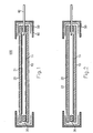
- FIG. 1 illustrates, in a schematic sectional view, a first embodiment of a sample chamber 100 according to the invention.
- the sample chamber 100 is formed by the base plate 10, the cover plate 20 and the spacer 30, in which at least one media connection 40 is embedded.
- the media connection is a fluid or gas connection.
- a plan view of the composite of carrier and cover plates 10, 20 and the film 50 is illustrated in FIG.
- the support plate 10 is a flat glass plate with a surface in the range of about 20 mm 20 mm to about 80 mm 120 mm. It carries on the side facing the chamber inside a sample assembly 11.
- the sample assembly 11 is, for example, a DNA array.
- the samples are applied prior to the reaction in the disassembled state of the sample chamber 100 on the support plate 10 by methods known per se (eg spotting) and contain, for example, in each case one DNA molecule or section.
- the carrier plate 10 usually has the same structure as a substrate in conventional DNA chips or hybridization chambers. The thickness of the carrier plate 10 is about 0.1 mm to 2 mm.
- the cover plate 20 is in the embodiment shown in Figure 1 as the support plate 10 is a glass plate with a mounted on the inside of the chamber side sample assembly 21.
- the carrier and cover plates 10, 20 are identical in this design.
- the sample arrangements 11, 21 may comprise, for example, DNA arrays, protein arrays or immunoarrays.
- the spacer 30 is in the form of a strip encircling the edges of the plate surfaces.
- the Strip consists for example of silicone rubber or PMMA and has a width of 1 mm to 3 mm or a thickness of about 0.05 to 1.0 mm.
- the thickness of the spacer 30 is adapted to the particular experimental conditions and is preferably selected so that a needle-shaped fluid port 40 can be pushed through the spacer without touching the adjacent plates. It is particularly advantageous that between the spacer 30 and the adjacent plates 10, 20 only a positive contact must be given. It is not mandatory that a liquid-tight joint is formed. Accordingly, it is also not mandatory that the spacer 30 is formed of a one-piece, circumferential strip. It can also be composed of several sections, the ends of which lie flush against each other.
- the media connection 40 is preferably formed by at least one injection needle.
- the top view according to FIG. 3 shows three injection needles 41, 42 and 43 for supplying fluid (injection of a test solution) or for discharging fluid and for discharging the gas displaced from the sample chamber during fluid supply.
- An injection needle 41 has, for example, an outer diameter of about 0.04 mm to 0.4 mm.
- the film 50 seals the plate assembly liquid tight along its edges.
- the foil 50 which optionally consists of a plurality of overlapping foil strips, forms on each side of the sample chamber 100 an envelope of U-shaped cross-section which covers the adjacent edges of the carrier and cover plates 10, 20 and the space formed by the spacer 30 .
- the film 50 preferably consists of a self-adhesive film material (eg so-called Parafilm "M", manufacturer: “Laboratory Film”, American National Can Chicago, USA). But it can also be provided a film strip with an adhesive layer. In this case, however, a liquid exchange between the interior of the sample chamber and the film 50 must be excluded.
- FIG. 1 additionally shows a sealing layer 60 which covers the film 50 at the edges of the plates 10, 20.
- the sealing layer 60 is not a mandatory feature of the invention. However, it is advantageously used to further increase the tightness of the chamber edges.
- the application of the sealing layer 60 takes place, for example, by immersing the sample chamber 100 with its edges, which are closed with the film 50, in a wax-melt bath.
- the sealant wax can be made from any suitable wax and / or paraffin mixture, e.g. B. consist of household candle wax.
- FIG. 2 shows an alternative embodiment of the invention in which the sample chamber 100 has essentially the same structure as in the embodiment according to FIG. 1.
- the difference relates only to the cover plate 20 which carries a filter device 22.
- the filter device 22 is shown schematically as an outer coating.
- An optical filter material may alternatively be mounted inside the sample chamber 100.
- the cover plate 20 may also consist of the filter material itself.
- the filter device 22 is preferably a multiple bandpass filter (eg, a double bandpass filter) that is transmissive for at least two (eg, four or more) separate wavelengths of light. This allows the detection of different fluorescent markers, which are bound to specific samples depending on the reaction result.
- a multiple bandpass filter eg, a double bandpass filter
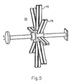
- FIG. 4 illustrate various forms of support means with which the sample chamber according to the invention is advantageously used.
- the mounting device 70 according to FIG. 4 comprises a thermoblock 71, into which the sample chamber 100 (drawn in dashed lines) is embedded.
- the sample chamber 100 is held on the thermal block 71 with an attachment 72, which serves to fix the sample chamber 100 and the alignment of connecting leads 80.
- the Connecting lines 80 are connected to the fluid ports (eg, 41-43) of the sample chamber 100.
- the attachment 72 has a window corresponding to the size of the sample arrangement on the carrier plate and possibly the cover plate. Through the window 73, the fluorescence detection takes place on the samples.
- the mounting device 70 comprises at least one mounting strip 75 to which a sample chamber (not shown) can be clamped with a side edge and the samples are pivotable a horizontally oriented axis of rotation.
- a star-shaped support means 70 is provided with eight pairs of support strips 75, 76, ..., with which simultaneously sixteen sample chambers can be pivoted.
- a plurality of such star-shaped holding devices can be arranged along a common shaft. Typical swing speeds are in the range of typically 10 revolutions per minute.
- a sample chamber according to the invention is used as follows. First, the support plate 10 and also the cover plate 20 with a sample arrangement according to the o. G. Examples loaded. For example, about 100,000 samples are spotted on the plates. Subsequently, the spacer 30 (see FIG. 1) is placed on the carrier plate 10 and the cover plate 20 is placed on the spacer 30. The structure is closed by attaching the encircling film 50. Subsequently, the sample chamber is optionally additionally sealed by immersion in a wax melt.
- the feed is made by injecting a test solution containing, for example, test DNA.
- a test solution containing, for example, test DNA.
- the film 50 and the spacer 30 at predetermined positions with the Pierced fluid port 40.
- a particular advantage of the invention is given by the fact that this piercing can be performed without additional sealing precautions. If a sample chamber according to FIG. 4 is anchored in a thermoblock, the injection takes place via the connection lines 80.
- the actual reaction takes place between the test solution and the samples 11 or 21 and / or application-dependent feeding of washing and / or detection solutions.
- the sample chamber is irradiated with a wavelength selected as a function of the marker dye used.
- the fluorescence detection takes place through the cover plate 20.
- the sample arrangement 11 or 21 is scanned point by point by an excitation laser and the fluorescence is measured synchronously. It may also be provided with a stimulation equipped with emission filters white light source. Alternatively, when using the filter device 22 (see FIG. 2), simultaneous excitation of all samples with a fanned-out excitation laser and parallel detection of the light emissions by the filter device 22 are provided.
- the sample chamber can be equipped with an electronic filter device which forms an electron optics for mass spectroscopic examinations of the samples.
Claims (17)
- Chambre d'échantillon (100) pour le traitement fluide d'au moins un échantillon, la chambre d'échantillon (100)- comprenant une structure constituée d'une plaque de support (10) pour une première disposition d'échantillon (11) et une plaque de recouvrement (20) pour recouvrir la première disposition d'échantillon qui sont séparées l'une de l'autre par un élément d'espacement (30),- la plaque de support (10) et la plaque de recouvrement (20) présentant la même taille, et- l'élément d'espacement (30) étant une bande circulaire sur le bord des côtés tournés l'un vers l'autre des plaques de support et de recouvrement (10, 20),caractérisée en ce que- la structure comprenant les plaques de support et de recouvrement (10, 20) et l'élément d'espacement (30) est maintenue par une feuille (50) circulaire sur le bord de la chambre d'échantillon (100) qui est formée par au moins une bande de feuille qui recouvre comme enveloppe circulaire les bords des plaques de support et de recouvrement (10, 20) et l'intervalle entre les plaques de support et de couvercle (10, 20).
- Chambre d'échantillon selon la revendication 1, dans laquelle les plaques de support et de recouvrement (10, 20) sont des plaques de verre de même forme.
- Chambre d'échantillon selon la revendication 1 ou 2, dans laquelle la plaque de recouvrement (20) porte sur le côté dirigé vers l'intérieur de la chambre d'échantillon (100), une deuxième disposition d'échantillon (21).
- Chambre d'échantillon selon l'une quelconque des revendications précédentes, dans laquelle la plaque de recouvrement (20) est dotée d'un dispositif de filtrage optique (22).
- Chambre d'échantillon selon la revendication 4, dans laquelle le dispositif de filtrage comprend un filtre passe-bande multiple qui est disposé de façon à laisser passer au moins deux longueurs d'ondes séparées.
- Chambre d'échantillon selon l'une quelconque des revendications précédentes, dans laquelle est prévue sur les bords des plaques de support et de recouvrement (10, 20) une couche d'étanchéité (60) sur la feuille (50).
- Chambre d'échantillon selon la revendication 6, dans laquelle la couche d'étanchéité (60) est en cire.
- Chambre d'échantillon selon l'une quelconque des revendications précédentes, dans laquelle au moins un raccord de fluide (40) est intégré dans l'élément d'espacement (30).
- Chambre d'échantillon selon la revendication 8, dans laquelle le raccord de fluide (40) comprend au moins une aiguille pour injection (41 à 43).
- Chambre d'échantillon selon l'une quelconque des revendications précédentes, qui est dotée d'un dispositif de maintien (70).
- Chambre d'échantillon selon la revendication 10, dans laquelle le dispositif de maintien (70) comprend un bloc thermique (71) et un couvercle (72) présentant une fenêtre (73) pour mesurer la fluorescence des échantillons dans la chambre d'échantillon (100).
- Chambre d'échantillon selon la revendication 11, dans laquelle le dispositif de maintien (70) comprend au moins une barre de maintien pivotante (75, 76).
- Chambre d'échantillon selon l'une quelconque des revendications précédentes, équipée d'un dispositif de filtrage électronique qui forme une optique électronique pour les analyses de spectre de masse.
- Procédé de réalisation d'une réaction chimique entre des échantillons fixés sur un support et une solution test, comprenant les étapes consistant à :- placer l'échantillon sur une plaque de support (10),- mettre en place un élément d'espacement (30) sur la plaque de support (10) et- placer une plaque de recouvrement (20) sur l'élément d'espacement (30), caractérisé par les étapes comprenant :- la formation d'une composition étanche aux liquides constituée d'une plaque de support et d'une plaque de recouvrement (10, 20) et de l'élément d'espacement (30) avec une feuille (50) enveloppant les bords de la plaque et l'intervalle entre les plaques,- l'insertion d'au moins un raccord fluide (40) au travers de la feuille (50) et de l'élément d'espacement (30),- l'injection de la solution de test dans la chambre d'échantillon (100) formée par les plaques de support et de recouvrement (10, 20) et l'élément d'espacement (30),- l'interaction entre l'échantillon et la solution de test dans des conditions réactionnelles prédéterminées, et- la mesure de la fluorescence des échantillons fixés au support pour saisir les résultats de la réaction.
- Procédé selon la revendication 14, dans lequel après avoir refermé la chambre d'échantillon (100) avec la feuille (50), les bords de la chambre d'échantillon (110) sont plongés dans un bain de cire fondue pour former sur les bords de la chambre, une couche d'étanchéité (60).
- Procédé selon la revendication 14 ou 15, dans lequel s'effectue une climatisation ou un pivotement de la chambre d'échantillon (100), pour régler les conditions réactionnelles prédéterminées.
- Utilisation d'une chambre d'échantillon ou d'un procédé selon l'une quelconque des revendications précédentes pour l'analyse de l'interaction des fragments d'ADN avec une molécule d'ADN test, des réactions d'hybridation, des réactions de coloration immunologique et/ou en combinaison avec des moyens de détection optiques, d'analyses par spectroscopie de masse ou des mesures de la résonance plasmonique de surface.
Applications Claiming Priority (3)
| Application Number | Priority Date | Filing Date | Title |
|---|---|---|---|
| DE10014204A DE10014204C2 (de) | 2000-03-22 | 2000-03-22 | Mikrohybridisierungskammer |
| DE10014204 | 2000-03-22 | ||
| PCT/EP2001/003210 WO2001070399A1 (fr) | 2000-03-22 | 2001-03-21 | Chambre de microhybridation |
Publications (2)
| Publication Number | Publication Date |
|---|---|
| EP1286771A1 EP1286771A1 (fr) | 2003-03-05 |
| EP1286771B1 true EP1286771B1 (fr) | 2006-06-07 |
Family
ID=7635895
Family Applications (1)
| Application Number | Title | Priority Date | Filing Date |
|---|---|---|---|
| EP01927767A Expired - Lifetime EP1286771B1 (fr) | 2000-03-22 | 2001-03-21 | Chambre de microhybridation |
Country Status (4)
| Country | Link |
|---|---|
| EP (1) | EP1286771B1 (fr) |
| AT (1) | ATE328662T1 (fr) |
| DE (2) | DE10014204C2 (fr) |
| WO (1) | WO2001070399A1 (fr) |
Families Citing this family (9)
| Publication number | Priority date | Publication date | Assignee | Title |
|---|---|---|---|---|
| US6225109B1 (en) * | 1999-05-27 | 2001-05-01 | Orchid Biosciences, Inc. | Genetic analysis device |
| DE10251338B4 (de) * | 2002-11-05 | 2008-05-21 | Intavis Bioanalytical Instruments Ag | Vorrichtung zur Durchführung von Färbe- und Hybridisierungsreaktionen |
| US20040248287A1 (en) * | 2003-03-28 | 2004-12-09 | Qianjin Hu | Multi-array systems and methods of use thereof |
| US8039817B2 (en) | 2008-05-05 | 2011-10-18 | Illumina, Inc. | Compensator for multiple surface imaging |
| US9352315B2 (en) | 2013-09-27 | 2016-05-31 | Taiwan Semiconductor Manufacturing Company, Ltd. | Method to produce chemical pattern in micro-fluidic structure |
| CN106635747A (zh) * | 2017-02-15 | 2017-05-10 | 中国人民解放军军事医学科学院基础医学研究所 | 一种纸基微流控快速核酸提取装置 |
| WO2020118255A1 (fr) | 2018-12-07 | 2020-06-11 | Element Biosciences, Inc. | Dispositif de cellule d'écoulement et son utilisation |
| US11053540B1 (en) | 2020-01-17 | 2021-07-06 | Element Biosciences, Inc. | High performance fluorescence imaging module for genomic testing assay |
| US11198121B1 (en) | 2020-06-10 | 2021-12-14 | Element Biosciences, Inc. | Flow cell systems and devices |
Citations (1)
| Publication number | Priority date | Publication date | Assignee | Title |
|---|---|---|---|---|
| US4010554A (en) * | 1976-02-13 | 1977-03-08 | Compton Robert W | Anatomical display device and process for preparing and displaying anatomical organ specimens |
Family Cites Families (10)
| Publication number | Priority date | Publication date | Assignee | Title |
|---|---|---|---|---|
| US4109431A (en) * | 1974-03-25 | 1978-08-29 | Ppg Industries, Inc. | Sealing and spacing unit for multiple glazed windows |
| AU592174B2 (en) * | 1987-02-17 | 1990-01-04 | Genesis Labs, Inc. | Immunoassay test strip |
| DE58907327D1 (de) * | 1988-06-01 | 1994-05-05 | Deutsche Aerospace | Vorrichtung mit Träger besonderer Struktur zur Aufnahme, Untersuchung und Behandlung von Proben. |
| US5100626A (en) * | 1990-05-24 | 1992-03-31 | Levin Andrew E | Binding assay device with removable cassette and manifold |
| FR2678950B1 (fr) * | 1991-07-09 | 1993-11-05 | Bertin Et Cie | Cartouche, dispositif et procede d'extraction d'acides nucleiques tels que l'adn a partir d'un echantillon de sang ou de cellules de tissus. |
| DE4409786A1 (de) * | 1994-03-22 | 1995-09-28 | Boehringer Mannheim Gmbh | Objektträger zur mikroskopischen Auswertung flüssiger Proben |
| DE4417079C2 (de) * | 1994-05-17 | 1998-06-10 | Fraunhofer Ges Forschung | Objektträger zum Beobachten von biologischem Material |
| DE69738996D1 (de) * | 1996-05-30 | 2008-10-30 | Cellomics Inc | Miniaturisierte zellenanordnung und verfahren und vorrichtung zum screening mittels zellen |
| US6180314B1 (en) * | 1998-05-27 | 2001-01-30 | Becton, Dickinson And Company | Method for preparing thin liquid samples for microscopic analysis |
| US6358475B1 (en) * | 1998-05-27 | 2002-03-19 | Becton, Dickinson And Company | Device for preparing thin liquid for microscopic analysis |
-
2000
- 2000-03-22 DE DE10014204A patent/DE10014204C2/de not_active Expired - Fee Related
-
2001
- 2001-03-21 WO PCT/EP2001/003210 patent/WO2001070399A1/fr active IP Right Grant
- 2001-03-21 EP EP01927767A patent/EP1286771B1/fr not_active Expired - Lifetime
- 2001-03-21 AT AT01927767T patent/ATE328662T1/de not_active IP Right Cessation
- 2001-03-21 DE DE50110042T patent/DE50110042D1/de not_active Expired - Lifetime
Patent Citations (1)
| Publication number | Priority date | Publication date | Assignee | Title |
|---|---|---|---|---|
| US4010554A (en) * | 1976-02-13 | 1977-03-08 | Compton Robert W | Anatomical display device and process for preparing and displaying anatomical organ specimens |
Also Published As
| Publication number | Publication date |
|---|---|
| DE10014204A1 (de) | 2001-10-04 |
| DE10014204C2 (de) | 2002-08-14 |
| DE50110042D1 (de) | 2006-07-20 |
| WO2001070399A1 (fr) | 2001-09-27 |
| ATE328662T1 (de) | 2006-06-15 |
| EP1286771A1 (fr) | 2003-03-05 |
Similar Documents
| Publication | Publication Date | Title |
|---|---|---|
| DE60031506T2 (de) | Fasermatrix zum zusammenbringen von chemischen stoffen, sowie verfahren zur herstellung und anwendung davon | |
| EP1807208B1 (fr) | Dispositif d'analyse de proteine et d'adn integree et automatisee dans une cartouche a usage unique, procede de production de cette cartouche et procede de fonctionnement de l'analyse de proteine et d'adn a l'aide de cette cartouche | |
| DE19941905C2 (de) | Probenkammer zur Flüssigkeitsbehandlung biologischer Proben | |
| DE112013003324B4 (de) | Integrierte Vorverarbeitungs-/Elektrophoresekartusche und integriertes Vorverarbeitungs-Kapillarelektrophoresegerät | |
| DE19740263C2 (de) | Kachelungsverfahren zum Bauen eines chemischen Arrays | |
| DE10142789C1 (de) | Bewegungselement für kleine Flüssigkeitsmengen | |
| EP1277055B1 (fr) | Biopuce pour l'archivage et l'analyse en laboratoire medical d'un echantillon biologique | |
| WO1995001559A2 (fr) | Porte-echantillons et son utilisation | |
| EP2324911A2 (fr) | Traitement d'échantillons dans des solutions ayant une petite surface de contact de paroi | |
| DE19940749A1 (de) | Verfahren und Vorrichtung zur integrierten Synthese und Analyse von Polymeren | |
| EP1286771B1 (fr) | Chambre de microhybridation | |
| EP2872254A1 (fr) | Procédé et dispositif d'analyse pour l'examen microscopique d'une coupe histologique ou d'un frottis de cellules | |
| DE10233212B4 (de) | Messvorrichtung mit einer Biochip-Anordnung und Verwendung der Vorrichtung für ein Hochdurchsatzanalyseverfahren | |
| DE60034007T2 (de) | Klebeetikett mit Gitter für Mikroskopobjektträger | |
| DE102005049976A1 (de) | Anordnung zur integrierten und automatisierten DNA- oder Protein-Analyse in einer einmal verwendbaren Cartridge, Herstellungsverfahren für eine solche Cartridge und Betriebsverfahren der DNA- oder Protein-Analyse unter Verwendung einer solchen Cartridge | |
| WO2009127394A2 (fr) | Dispositif automatique pour la mise en œuvre de réactions de détection, et procédé de dosage de réactifs sur des porte-objets | |
| DE102012013680A1 (de) | Vorrichtung sowie Verfahren zur Inkubation von Patientenproben | |
| DE4120139A1 (de) | Enzymimmunoassay-verfahren und testset hierzu | |
| DE112018007860T5 (de) | Biochemische Kassette und biochemische Analysevorrichtung | |
| WO2015062715A1 (fr) | Dispositif amélioré et procédé de conduite de réactions entre une phase solide et une phase liquide | |
| DE112018007861T5 (de) | Biochemische Kassette und biochemische Analysevorrichtung | |
| DE10339996A1 (de) | Analyseverfahren, Analysevorrichtung und Analysechip zur Analyse von Reagenzien | |
| EP1360492B1 (fr) | Porte-echantillon pour echantillons chimiques et biologiques | |
| DE3107964A1 (de) | Gestell fuer ein mikroanalysensystem | |
| DE10058095C2 (de) | Vorrichtung zur Bestimmung von Analyten durch Chemilumineszenz |
Legal Events
| Date | Code | Title | Description |
|---|---|---|---|
| PUAI | Public reference made under article 153(3) epc to a published international application that has entered the european phase |
Free format text: ORIGINAL CODE: 0009012 |
|
| 17P | Request for examination filed |
Effective date: 20020722 |
|
| AK | Designated contracting states |
Designated state(s): AT BE CH CY DE DK ES FI FR GB GR IE IT LI LU MC NL PT SE TR Kind code of ref document: A1 Designated state(s): AT BE CH CY DE DK ES FI FR GB GR IE IT LI LU MC NL PT SE TR |
|
| RIN1 | Information on inventor provided before grant (corrected) |
Inventor name: EICKHOFF, DR. HOLGER Inventor name: TANDON, NEERAJ Inventor name: LEHRACH, HANS |
|
| RIN1 | Information on inventor provided before grant (corrected) |
Inventor name: TANDON, NEERAJ Inventor name: LEHRACH, HANS, PROF. DR. Inventor name: EICKHOFF, DR. HOLGER |
|
| 17Q | First examination report despatched |
Effective date: 20031008 |
|
| GRAP | Despatch of communication of intention to grant a patent |
Free format text: ORIGINAL CODE: EPIDOSNIGR1 |
|
| GRAS | Grant fee paid |
Free format text: ORIGINAL CODE: EPIDOSNIGR3 |
|
| GRAA | (expected) grant |
Free format text: ORIGINAL CODE: 0009210 |
|
| AK | Designated contracting states |
Kind code of ref document: B1 Designated state(s): AT BE CH CY DE DK ES FI FR GB GR IE IT LI LU MC NL PT SE TR |
|
| PG25 | Lapsed in a contracting state [announced via postgrant information from national office to epo] |
Ref country code: IT Free format text: LAPSE BECAUSE OF FAILURE TO SUBMIT A TRANSLATION OF THE DESCRIPTION OR TO PAY THE FEE WITHIN THE PRESCRIBED TIME-LIMIT;WARNING: LAPSES OF ITALIAN PATENTS WITH EFFECTIVE DATE BEFORE 2007 MAY HAVE OCCURRED AT ANY TIME BEFORE 2007. THE CORRECT EFFECTIVE DATE MAY BE DIFFERENT FROM THE ONE RECORDED. Effective date: 20060607 Ref country code: GB Free format text: LAPSE BECAUSE OF FAILURE TO SUBMIT A TRANSLATION OF THE DESCRIPTION OR TO PAY THE FEE WITHIN THE PRESCRIBED TIME-LIMIT Effective date: 20060607 Ref country code: IE Free format text: LAPSE BECAUSE OF FAILURE TO SUBMIT A TRANSLATION OF THE DESCRIPTION OR TO PAY THE FEE WITHIN THE PRESCRIBED TIME-LIMIT Effective date: 20060607 Ref country code: NL Free format text: LAPSE BECAUSE OF FAILURE TO SUBMIT A TRANSLATION OF THE DESCRIPTION OR TO PAY THE FEE WITHIN THE PRESCRIBED TIME-LIMIT Effective date: 20060607 Ref country code: FI Free format text: LAPSE BECAUSE OF FAILURE TO SUBMIT A TRANSLATION OF THE DESCRIPTION OR TO PAY THE FEE WITHIN THE PRESCRIBED TIME-LIMIT Effective date: 20060607 |
|
| REG | Reference to a national code |
Ref country code: GB Ref legal event code: FG4D Free format text: NOT ENGLISH |
|
| REG | Reference to a national code |
Ref country code: CH Ref legal event code: EP |
|
| REG | Reference to a national code |
Ref country code: IE Ref legal event code: FG4D Free format text: LANGUAGE OF EP DOCUMENT: GERMAN |
|
| REF | Corresponds to: |
Ref document number: 50110042 Country of ref document: DE Date of ref document: 20060720 Kind code of ref document: P |
|
| REG | Reference to a national code |
Ref country code: CH Ref legal event code: NV Representative=s name: RITSCHER & PARTNER AG |
|
| PG25 | Lapsed in a contracting state [announced via postgrant information from national office to epo] |
Ref country code: SE Free format text: LAPSE BECAUSE OF FAILURE TO SUBMIT A TRANSLATION OF THE DESCRIPTION OR TO PAY THE FEE WITHIN THE PRESCRIBED TIME-LIMIT Effective date: 20060907 Ref country code: DK Free format text: LAPSE BECAUSE OF FAILURE TO SUBMIT A TRANSLATION OF THE DESCRIPTION OR TO PAY THE FEE WITHIN THE PRESCRIBED TIME-LIMIT Effective date: 20060907 |
|
| PG25 | Lapsed in a contracting state [announced via postgrant information from national office to epo] |
Ref country code: ES Free format text: LAPSE BECAUSE OF FAILURE TO SUBMIT A TRANSLATION OF THE DESCRIPTION OR TO PAY THE FEE WITHIN THE PRESCRIBED TIME-LIMIT Effective date: 20060918 |
|
| PG25 | Lapsed in a contracting state [announced via postgrant information from national office to epo] |
Ref country code: PT Free format text: LAPSE BECAUSE OF FAILURE TO SUBMIT A TRANSLATION OF THE DESCRIPTION OR TO PAY THE FEE WITHIN THE PRESCRIBED TIME-LIMIT Effective date: 20061107 |
|
| NLV1 | Nl: lapsed or annulled due to failure to fulfill the requirements of art. 29p and 29m of the patents act | ||
| GBV | Gb: ep patent (uk) treated as always having been void in accordance with gb section 77(7)/1977 [no translation filed] |
Effective date: 20060607 |
|
| REG | Reference to a national code |
Ref country code: IE Ref legal event code: FD4D |
|
| PLBE | No opposition filed within time limit |
Free format text: ORIGINAL CODE: 0009261 |
|
| STAA | Information on the status of an ep patent application or granted ep patent |
Free format text: STATUS: NO OPPOSITION FILED WITHIN TIME LIMIT |
|
| EN | Fr: translation not filed | ||
| 26N | No opposition filed |
Effective date: 20070308 |
|
| BERE | Be: lapsed |
Owner name: MAX-PLANCK-GESELLSCHAFT ZUR FORDERUNG DER WISSEN Effective date: 20070331 |
|
| PG25 | Lapsed in a contracting state [announced via postgrant information from national office to epo] |
Ref country code: BE Free format text: LAPSE BECAUSE OF NON-PAYMENT OF DUE FEES Effective date: 20070331 |
|
| PG25 | Lapsed in a contracting state [announced via postgrant information from national office to epo] |
Ref country code: MC Free format text: LAPSE BECAUSE OF NON-PAYMENT OF DUE FEES Effective date: 20070331 |
|
| REG | Reference to a national code |
Ref country code: CH Ref legal event code: PCAR Free format text: RITSCHER & PARTNER AG;RESIRAIN 1;8125 ZOLLIKERBERG (CH) |
|
| PG25 | Lapsed in a contracting state [announced via postgrant information from national office to epo] |
Ref country code: GR Free format text: LAPSE BECAUSE OF FAILURE TO SUBMIT A TRANSLATION OF THE DESCRIPTION OR TO PAY THE FEE WITHIN THE PRESCRIBED TIME-LIMIT Effective date: 20060908 Ref country code: FR Free format text: LAPSE BECAUSE OF FAILURE TO SUBMIT A TRANSLATION OF THE DESCRIPTION OR TO PAY THE FEE WITHIN THE PRESCRIBED TIME-LIMIT Effective date: 20070309 |
|
| PG25 | Lapsed in a contracting state [announced via postgrant information from national office to epo] |
Ref country code: FR Free format text: LAPSE BECAUSE OF FAILURE TO SUBMIT A TRANSLATION OF THE DESCRIPTION OR TO PAY THE FEE WITHIN THE PRESCRIBED TIME-LIMIT Effective date: 20060607 |
|
| PG25 | Lapsed in a contracting state [announced via postgrant information from national office to epo] |
Ref country code: CY Free format text: LAPSE BECAUSE OF FAILURE TO SUBMIT A TRANSLATION OF THE DESCRIPTION OR TO PAY THE FEE WITHIN THE PRESCRIBED TIME-LIMIT Effective date: 20060607 Ref country code: LU Free format text: LAPSE BECAUSE OF NON-PAYMENT OF DUE FEES Effective date: 20070321 |
|
| PG25 | Lapsed in a contracting state [announced via postgrant information from national office to epo] |
Ref country code: TR Free format text: LAPSE BECAUSE OF FAILURE TO SUBMIT A TRANSLATION OF THE DESCRIPTION OR TO PAY THE FEE WITHIN THE PRESCRIBED TIME-LIMIT Effective date: 20060607 |
|
| PGFP | Annual fee paid to national office [announced via postgrant information from national office to epo] |
Ref country code: CH Payment date: 20100316 Year of fee payment: 10 |
|
| PGFP | Annual fee paid to national office [announced via postgrant information from national office to epo] |
Ref country code: AT Payment date: 20100308 Year of fee payment: 10 |
|
| PGFP | Annual fee paid to national office [announced via postgrant information from national office to epo] |
Ref country code: DE Payment date: 20100505 Year of fee payment: 10 |
|
| REG | Reference to a national code |
Ref country code: CH Ref legal event code: PL |
|
| PG25 | Lapsed in a contracting state [announced via postgrant information from national office to epo] |
Ref country code: AT Free format text: LAPSE BECAUSE OF NON-PAYMENT OF DUE FEES Effective date: 20110321 |
|
| PG25 | Lapsed in a contracting state [announced via postgrant information from national office to epo] |
Ref country code: LI Free format text: LAPSE BECAUSE OF NON-PAYMENT OF DUE FEES Effective date: 20110331 Ref country code: DE Free format text: LAPSE BECAUSE OF NON-PAYMENT OF DUE FEES Effective date: 20111001 Ref country code: CH Free format text: LAPSE BECAUSE OF NON-PAYMENT OF DUE FEES Effective date: 20110331 |
|
| REG | Reference to a national code |
Ref country code: DE Ref legal event code: R119 Ref document number: 50110042 Country of ref document: DE Effective date: 20111001 |