EP1286771B1 - Microhybridisation chamber - Google Patents
Microhybridisation chamber Download PDFInfo
- Publication number
- EP1286771B1 EP1286771B1 EP01927767A EP01927767A EP1286771B1 EP 1286771 B1 EP1286771 B1 EP 1286771B1 EP 01927767 A EP01927767 A EP 01927767A EP 01927767 A EP01927767 A EP 01927767A EP 1286771 B1 EP1286771 B1 EP 1286771B1
- Authority
- EP
- European Patent Office
- Prior art keywords
- sample chamber
- sample
- spacer
- plates
- support
- Prior art date
- Legal status (The legal status is an assumption and is not a legal conclusion. Google has not performed a legal analysis and makes no representation as to the accuracy of the status listed.)
- Expired - Lifetime
Links
Images

Classifications
-
- B—PERFORMING OPERATIONS; TRANSPORTING
- B01—PHYSICAL OR CHEMICAL PROCESSES OR APPARATUS IN GENERAL
- B01L—CHEMICAL OR PHYSICAL LABORATORY APPARATUS FOR GENERAL USE
- B01L3/00—Containers or dishes for laboratory use, e.g. laboratory glassware; Droppers
- B01L3/50—Containers for the purpose of retaining a material to be analysed, e.g. test tubes
- B01L3/508—Containers for the purpose of retaining a material to be analysed, e.g. test tubes rigid containers not provided for above
-
- B—PERFORMING OPERATIONS; TRANSPORTING
- B01—PHYSICAL OR CHEMICAL PROCESSES OR APPARATUS IN GENERAL
- B01L—CHEMICAL OR PHYSICAL LABORATORY APPARATUS FOR GENERAL USE
- B01L9/00—Supporting devices; Holding devices
- B01L9/52—Supports specially adapted for flat sample carriers, e.g. for plates, slides, chips
-
- B—PERFORMING OPERATIONS; TRANSPORTING
- B01—PHYSICAL OR CHEMICAL PROCESSES OR APPARATUS IN GENERAL
- B01L—CHEMICAL OR PHYSICAL LABORATORY APPARATUS FOR GENERAL USE
- B01L2200/00—Solutions for specific problems relating to chemical or physical laboratory apparatus
- B01L2200/02—Adapting objects or devices to another
- B01L2200/026—Fluid interfacing between devices or objects, e.g. connectors, inlet details
-
- B—PERFORMING OPERATIONS; TRANSPORTING
- B01—PHYSICAL OR CHEMICAL PROCESSES OR APPARATUS IN GENERAL
- B01L—CHEMICAL OR PHYSICAL LABORATORY APPARATUS FOR GENERAL USE
- B01L2200/00—Solutions for specific problems relating to chemical or physical laboratory apparatus
- B01L2200/06—Fluid handling related problems
- B01L2200/0689—Sealing
-
- B—PERFORMING OPERATIONS; TRANSPORTING
- B01—PHYSICAL OR CHEMICAL PROCESSES OR APPARATUS IN GENERAL
- B01L—CHEMICAL OR PHYSICAL LABORATORY APPARATUS FOR GENERAL USE
- B01L2300/00—Additional constructional details
- B01L2300/06—Auxiliary integrated devices, integrated components
- B01L2300/0627—Sensor or part of a sensor is integrated
- B01L2300/0636—Integrated biosensor, microarrays
-
- B—PERFORMING OPERATIONS; TRANSPORTING
- B01—PHYSICAL OR CHEMICAL PROCESSES OR APPARATUS IN GENERAL
- B01L—CHEMICAL OR PHYSICAL LABORATORY APPARATUS FOR GENERAL USE
- B01L2300/00—Additional constructional details
- B01L2300/08—Geometry, shape and general structure
- B01L2300/0809—Geometry, shape and general structure rectangular shaped
- B01L2300/0822—Slides
-
- B—PERFORMING OPERATIONS; TRANSPORTING
- B01—PHYSICAL OR CHEMICAL PROCESSES OR APPARATUS IN GENERAL
- B01L—CHEMICAL OR PHYSICAL LABORATORY APPARATUS FOR GENERAL USE
- B01L2300/00—Additional constructional details
- B01L2300/08—Geometry, shape and general structure
- B01L2300/0861—Configuration of multiple channels and/or chambers in a single devices
- B01L2300/0877—Flow chambers
-
- B—PERFORMING OPERATIONS; TRANSPORTING
- B01—PHYSICAL OR CHEMICAL PROCESSES OR APPARATUS IN GENERAL
- B01L—CHEMICAL OR PHYSICAL LABORATORY APPARATUS FOR GENERAL USE
- B01L2300/00—Additional constructional details
- B01L2300/18—Means for temperature control
-
- B—PERFORMING OPERATIONS; TRANSPORTING
- B01—PHYSICAL OR CHEMICAL PROCESSES OR APPARATUS IN GENERAL
- B01L—CHEMICAL OR PHYSICAL LABORATORY APPARATUS FOR GENERAL USE
- B01L7/00—Heating or cooling apparatus; Heat insulating devices
- B01L7/52—Heating or cooling apparatus; Heat insulating devices with provision for submitting samples to a predetermined sequence of different temperatures, e.g. for treating nucleic acid samples
- B01L7/525—Heating or cooling apparatus; Heat insulating devices with provision for submitting samples to a predetermined sequence of different temperatures, e.g. for treating nucleic acid samples with physical movement of samples between temperature zones
-
- G—PHYSICS
- G01—MEASURING; TESTING
- G01N—INVESTIGATING OR ANALYSING MATERIALS BY DETERMINING THEIR CHEMICAL OR PHYSICAL PROPERTIES
- G01N35/00—Automatic analysis not limited to methods or materials provided for in any single one of groups G01N1/00 - G01N33/00; Handling materials therefor
- G01N35/00029—Automatic analysis not limited to methods or materials provided for in any single one of groups G01N1/00 - G01N33/00; Handling materials therefor provided with flat sample substrates, e.g. slides
- G01N2035/00099—Characterised by type of test elements
- G01N2035/00158—Elements containing microarrays, i.e. "biochip"
-
- G—PHYSICS
- G01—MEASURING; TESTING
- G01N—INVESTIGATING OR ANALYSING MATERIALS BY DETERMINING THEIR CHEMICAL OR PHYSICAL PROPERTIES
- G01N35/00—Automatic analysis not limited to methods or materials provided for in any single one of groups G01N1/00 - G01N33/00; Handling materials therefor
- G01N2035/00465—Separating and mixing arrangements
- G01N2035/00475—Filters
- G01N2035/00485—Filters combined with sample carriers
-
- G—PHYSICS
- G01—MEASURING; TESTING
- G01N—INVESTIGATING OR ANALYSING MATERIALS BY DETERMINING THEIR CHEMICAL OR PHYSICAL PROPERTIES
- G01N35/00—Automatic analysis not limited to methods or materials provided for in any single one of groups G01N1/00 - G01N33/00; Handling materials therefor
- G01N35/00584—Control arrangements for automatic analysers
- G01N2035/0097—Control arrangements for automatic analysers monitoring reactions as a function of time
Definitions
- the invention generally relates to a sample chamber for the liquid treatment of at least one sample, in particular a sample chamber for fluid treatment of a plurality of samples, such.
- DNA chips In genetic engineering and biochemistry, it is generally known to examine samples of genetic materials with so-called DNA chips. Several thousand microscopically small samples are arrayed on a carrier plate on a DNA chip.
- the samples contain the biomolecules to be investigated, for example DNA, RNA, proteins or antibodies.
- the samples may already be marked, if later z. B. to be detected after a reaction or otherwise change with optical methods. Common detection methods are measurements of fluorescence, chemiluminescence or radioactivity. For other detection methods, such. As mass spectrometry, absorption measurements, or adsorption measurements, the sample molecules may also be unlabeled.
- the target molecule assembly on the support plate is overlaid with a test solution containing the sample molecules. Upon hybridization of certain sample molecules from the test solution to the target molecules immobilized on the support plate, a signal can be measured at the corresponding target molecules, which is typically a fluorescence signal.
- the carrier plate for example, loaded with a picking / spotting robot, was overlaid with the test solution and the test solution was covered with a cover glass.
- the cover glass as it is, for example, from microscopy is known, is a platelet with a thickness as small as possible, which floats on the test solution and is held over the surface tension on the support plate at a distance from the samples.
- This conventional technique of combining a backing plate with a thin coverslip has the advantage of low assay solution usage in the range of 10 ⁇ l to 20 ⁇ l per chip. But it also has the important disadvantages explained below.
- Sample throughput on a DNA chip has hitherto been limited by the sample density achievable with the robots currently in use.
- sample density achievable with the robots currently in use.
- sample throughput number of samples treated or used per experiment or per unit of line.
- Another disadvantage is that a composite of loaded carrier plate, over-coated test solution and cover glass is difficult to handle. An automated manipulation of the overall structure, eg. B. for a reproducible and uniform supply of the test solution is excluded.
- layered cuvettes which form closed sample chambers and are designed especially for optical measurements through the cuvettes.
- cuvettes have the advantage of high stability and correspondingly good handling.
- their use as a DNA chip is ruled out because the inner cuvette walls are not designed for sample placement with the commonly used spotting technique.
- the patent application WO 97/45730 A discloses a device with two plane-parallel glass plates, both of which are provided with samples or reagent matrices.
- U.S. Patent US-A-5,352,609 discloses an insert cassette for working out purified nucleic acids from cells comprising a dialysis chamber and a filter in the dialysis chamber.
- US Pat. No. 4,010,554 describes an apparatus for the preparation and visual presentation of organ samples in the form of anatomical sections.
- the organ samples are placed between two cover plates with which a liquid-tight chamber is formed.
- the sample chamber should also enable safe handling of radioactively labeled sample solutions.
- the sample chamber should in particular be designed for an increase in the sample throughput and facilitate the examination of samples after interaction with a test solution.
- the object of the invention is also to provide a method for carrying out genetic engineering studies with DNA chips.
- the basic idea of the invention is to provide a sample chamber comprising a carrier plate and a cover plate, which are arranged separated from one another by a spacer in the form of a strip encircling the edge of the mutually facing surfaces of the carrier and cover plates, wherein at least one fluid connection can be integrated in the spacers and the structure of carrier and cover plates and the spacer is held together by a liquid-tight film, wherein the carrier plate and the cover plate have the same size.
- the film is formed by at least one film strip, which covers the edges of the carrier and cover plates and the distance between the plates as a wrap-around envelope.
- a wax seal is provided on the composite between the plates and the foil.
- the wax seal comprises a wax layer covering at least the edge of the circulating film resting on the plates.
- the carrier and cover plates which are the same size, and the spacers are per se separate components of the sample chamber, which is held together as a composite (sandwich construction) only by the liquid-tight foil connection and optionally sealed by the wax seal.
- the spacer may have such a small thickness that the sample chamber of the present invention has substantially a chamber volume corresponding to a test solution amount as used in the conventional free-cover glass DNA chips.
- the cover plate not only fulfills a covering function.
- the cover plate is, in particular for increasing the sample throughput, even designed as the support plate as a carrier of a further sample arrangement and / or as a carrier of an optical filter device.
- a first embodiment of the sample chamber according to the invention in which the cover plate carries a sample arrangement (eg DNA array), has the advantage that two experiments can be carried out in parallel in a test solution feed. The sample throughput doubles. In addition, it is advantageous that the reaction conditions for both sample arrangements on the carrier or cover plate are identical.
- a sample arrangement eg DNA array
- the cover plate carries at least one optical filter
- an online detection is possible.
- the invention is application-dependent a sample chamber with or without media connection.
- a sample chamber without media connection can be provided as a prefabricated reaction mixture, which only when using z. B. is provided with fluid connections.
- the cover plate can carry both on the inside of a sample assembly and on the outside of a filter assembly.
- the cover plate can also be formed by a filter material itself.
- a particular advantage of the invention is the stability of the composite of plates and spacers held together only by a film strip.
- This allows the combination of the sample chamber with application-dependent designed holding devices.
- a support means for example, a thermoblock is provided, in which the sample chamber can be clamped as in a frame.
- the thermoblock contains a heater for setting a specific reaction temperature in the sample chamber.
- the sample chamber is fixed with an edge on a pivotable mounting bar. This allows a well-known pivoting of the sample chamber during the loading of the test solution and / or during the reaction, without causing stability problems. This is advantageous in particular for genetic engineering tasks for uniform hybridization.
- the invention has the following advantages. With simple and compatible with the usual laboratory technology means a sample chamber for fluid treatment is created, which is far superior to conventional DNA chips in terms of stability, manageability, usability and sample throughput. The reaction conditions are balanced for all samples and independent of any manual influences of the experimenter.
- the sample chamber according to the invention is suitable for use in an automated system and for combination with various detection methods, in particular optical measurements, activity measurements, surface plasmon resonance measurements and the like.
- the invention is explained below using the example of a microhybridization chamber for genetic engineering tasks, but without being limited to this application.
- the realization of the invention is particularly applicable to all methods in which the interaction of carrier-bound Samples (individual samples or sample arrangements), such as.
- carrier-bound Samples individual samples or sample arrangements
- chromosomes in situ hybridizations
- tissue Immunostaining
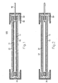
- FIG. 1 illustrates, in a schematic sectional view, a first embodiment of a sample chamber 100 according to the invention.
- the sample chamber 100 is formed by the base plate 10, the cover plate 20 and the spacer 30, in which at least one media connection 40 is embedded.
- the media connection is a fluid or gas connection.
- a plan view of the composite of carrier and cover plates 10, 20 and the film 50 is illustrated in FIG.
- the support plate 10 is a flat glass plate with a surface in the range of about 20 mm 20 mm to about 80 mm 120 mm. It carries on the side facing the chamber inside a sample assembly 11.
- the sample assembly 11 is, for example, a DNA array.
- the samples are applied prior to the reaction in the disassembled state of the sample chamber 100 on the support plate 10 by methods known per se (eg spotting) and contain, for example, in each case one DNA molecule or section.
- the carrier plate 10 usually has the same structure as a substrate in conventional DNA chips or hybridization chambers. The thickness of the carrier plate 10 is about 0.1 mm to 2 mm.
- the cover plate 20 is in the embodiment shown in Figure 1 as the support plate 10 is a glass plate with a mounted on the inside of the chamber side sample assembly 21.
- the carrier and cover plates 10, 20 are identical in this design.
- the sample arrangements 11, 21 may comprise, for example, DNA arrays, protein arrays or immunoarrays.
- the spacer 30 is in the form of a strip encircling the edges of the plate surfaces.
- the Strip consists for example of silicone rubber or PMMA and has a width of 1 mm to 3 mm or a thickness of about 0.05 to 1.0 mm.
- the thickness of the spacer 30 is adapted to the particular experimental conditions and is preferably selected so that a needle-shaped fluid port 40 can be pushed through the spacer without touching the adjacent plates. It is particularly advantageous that between the spacer 30 and the adjacent plates 10, 20 only a positive contact must be given. It is not mandatory that a liquid-tight joint is formed. Accordingly, it is also not mandatory that the spacer 30 is formed of a one-piece, circumferential strip. It can also be composed of several sections, the ends of which lie flush against each other.
- the media connection 40 is preferably formed by at least one injection needle.
- the top view according to FIG. 3 shows three injection needles 41, 42 and 43 for supplying fluid (injection of a test solution) or for discharging fluid and for discharging the gas displaced from the sample chamber during fluid supply.
- An injection needle 41 has, for example, an outer diameter of about 0.04 mm to 0.4 mm.
- the film 50 seals the plate assembly liquid tight along its edges.
- the foil 50 which optionally consists of a plurality of overlapping foil strips, forms on each side of the sample chamber 100 an envelope of U-shaped cross-section which covers the adjacent edges of the carrier and cover plates 10, 20 and the space formed by the spacer 30 .
- the film 50 preferably consists of a self-adhesive film material (eg so-called Parafilm "M", manufacturer: “Laboratory Film”, American National Can Chicago, USA). But it can also be provided a film strip with an adhesive layer. In this case, however, a liquid exchange between the interior of the sample chamber and the film 50 must be excluded.
- FIG. 1 additionally shows a sealing layer 60 which covers the film 50 at the edges of the plates 10, 20.
- the sealing layer 60 is not a mandatory feature of the invention. However, it is advantageously used to further increase the tightness of the chamber edges.
- the application of the sealing layer 60 takes place, for example, by immersing the sample chamber 100 with its edges, which are closed with the film 50, in a wax-melt bath.
- the sealant wax can be made from any suitable wax and / or paraffin mixture, e.g. B. consist of household candle wax.
- FIG. 2 shows an alternative embodiment of the invention in which the sample chamber 100 has essentially the same structure as in the embodiment according to FIG. 1.
- the difference relates only to the cover plate 20 which carries a filter device 22.
- the filter device 22 is shown schematically as an outer coating.
- An optical filter material may alternatively be mounted inside the sample chamber 100.
- the cover plate 20 may also consist of the filter material itself.
- the filter device 22 is preferably a multiple bandpass filter (eg, a double bandpass filter) that is transmissive for at least two (eg, four or more) separate wavelengths of light. This allows the detection of different fluorescent markers, which are bound to specific samples depending on the reaction result.
- a multiple bandpass filter eg, a double bandpass filter
- FIG. 4 illustrate various forms of support means with which the sample chamber according to the invention is advantageously used.
- the mounting device 70 according to FIG. 4 comprises a thermoblock 71, into which the sample chamber 100 (drawn in dashed lines) is embedded.
- the sample chamber 100 is held on the thermal block 71 with an attachment 72, which serves to fix the sample chamber 100 and the alignment of connecting leads 80.
- the Connecting lines 80 are connected to the fluid ports (eg, 41-43) of the sample chamber 100.
- the attachment 72 has a window corresponding to the size of the sample arrangement on the carrier plate and possibly the cover plate. Through the window 73, the fluorescence detection takes place on the samples.
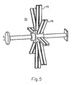
- the mounting device 70 comprises at least one mounting strip 75 to which a sample chamber (not shown) can be clamped with a side edge and the samples are pivotable a horizontally oriented axis of rotation.
- a star-shaped support means 70 is provided with eight pairs of support strips 75, 76, ..., with which simultaneously sixteen sample chambers can be pivoted.
- a plurality of such star-shaped holding devices can be arranged along a common shaft. Typical swing speeds are in the range of typically 10 revolutions per minute.
- a sample chamber according to the invention is used as follows. First, the support plate 10 and also the cover plate 20 with a sample arrangement according to the o. G. Examples loaded. For example, about 100,000 samples are spotted on the plates. Subsequently, the spacer 30 (see FIG. 1) is placed on the carrier plate 10 and the cover plate 20 is placed on the spacer 30. The structure is closed by attaching the encircling film 50. Subsequently, the sample chamber is optionally additionally sealed by immersion in a wax melt.
- the feed is made by injecting a test solution containing, for example, test DNA.
- a test solution containing, for example, test DNA.
- the film 50 and the spacer 30 at predetermined positions with the Pierced fluid port 40.
- a particular advantage of the invention is given by the fact that this piercing can be performed without additional sealing precautions. If a sample chamber according to FIG. 4 is anchored in a thermoblock, the injection takes place via the connection lines 80.
- the actual reaction takes place between the test solution and the samples 11 or 21 and / or application-dependent feeding of washing and / or detection solutions.
- the sample chamber is irradiated with a wavelength selected as a function of the marker dye used.
- the fluorescence detection takes place through the cover plate 20.
- the sample arrangement 11 or 21 is scanned point by point by an excitation laser and the fluorescence is measured synchronously. It may also be provided with a stimulation equipped with emission filters white light source. Alternatively, when using the filter device 22 (see FIG. 2), simultaneous excitation of all samples with a fanned-out excitation laser and parallel detection of the light emissions by the filter device 22 are provided.
- the sample chamber can be equipped with an electronic filter device which forms an electron optics for mass spectroscopic examinations of the samples.
Abstract
Description
Die Erfindung betrifft allgemein eine Probenkammer für die Flüssigkeitsbehandlung mindestens einer Probe, insbesondere eine Probenkammer zur Fluidbehandlung einer Vielzahl von Proben, wie z. B. eine Mikrohybridisierungskammer.The invention generally relates to a sample chamber for the liquid treatment of at least one sample, in particular a sample chamber for fluid treatment of a plurality of samples, such. B. a microhybridization chamber.
In der Gentechnik und Biochemie ist es allgemein bekannt, mit sog. DNA-Chips Proben aus genetischen Materialien zu untersuchen. Auf einem DNA-Chip sind mehrere tausend mikroskopisch kleine Proben arrayartig auf einer Trägerplatte angeordnet. Die Proben enthalten die zu untersuchenden Biomoleküle, bspw. DNA, RNA, Proteine oder Antikörper. Die Proben können bereits markiert sein, wenn sie später z. B. nach einer Reaktion oder anderweitigen Veränderung mit optischen Methoden detektiert werden sollen. Übliche Detektionsverfahren sind Messungen der Fluoreszenz, Chemolumineszenz oder Radioaktivität. Für andere Detektionsverfahren, wie z. B. Massenspektrometrie, Absorptionsmessungen, oder Adsorptionsmessungen können die Probenmoleküle auch unmarkiert sein. Die Zielmolekülanordnung auf der Trägerplatte wird mit einer Testlösung überschichtet, die die Probenmoleküle enthält. Bei Hybridisierung von bestimmten Probenmolekülen aus der Testlösung an die auf der Trägerplatte immobilisierten Zielmoleküle kann an den entsprechenden Zielmolekülen ein Signal gemessen werden, dass typischerweise ein Fluoreszenzsignal ist.In genetic engineering and biochemistry, it is generally known to examine samples of genetic materials with so-called DNA chips. Several thousand microscopically small samples are arrayed on a carrier plate on a DNA chip. The samples contain the biomolecules to be investigated, for example DNA, RNA, proteins or antibodies. The samples may already be marked, if later z. B. to be detected after a reaction or otherwise change with optical methods. Common detection methods are measurements of fluorescence, chemiluminescence or radioactivity. For other detection methods, such. As mass spectrometry, absorption measurements, or adsorption measurements, the sample molecules may also be unlabeled. The target molecule assembly on the support plate is overlaid with a test solution containing the sample molecules. Upon hybridization of certain sample molecules from the test solution to the target molecules immobilized on the support plate, a signal can be measured at the corresponding target molecules, which is typically a fluorescence signal.
Um mit einem einzelnen Chip eine möglichst große Anzahl von Proben parallel verarbeiten zu können, wurde in der DNA-Chip-Technologie bisher das Hauptaugenmerk auf die reproduzierbare und genaue, hochdichte Ablage von Proben auf der Trägerplatte gerichtet. Im praktischen Einsatz wurde die, bspw. mit einem Picking-/Spotting-Roboter beschickte, Trägerplatte mit der Testlösung überschichtet und die Testlösung mit einem Deckglas abgedeckt. Das Deckglas, wie es bspw. aus der Mikroskopie bekannt ist, ist ein Plättchen mit einer möglichst geringen Dicke, das auf der Testlösung aufschwimmt und über die Oberflächenspannung über der Trägerplatte mit Abstand von den Proben gehalten wird. Diese herkömmliche Technik der Kombination einer Trägerplatte mit einem dünnen Deckglas besitzt den Vorteil eines geringen Testlösungsverbrauchs im Bereich von 10 µl bis 20 µl pro Chip. Sie besitzt aber auch die im Folgenden erläuterten wichtigen Nachteile.In order to be able to process a large number of samples in parallel with a single chip, the main focus in DNA chip technology has been on the reproducible and accurate, high-density deposition of samples on the carrier plate. In practical use, the carrier plate, for example, loaded with a picking / spotting robot, was overlaid with the test solution and the test solution was covered with a cover glass. The cover glass, as it is, for example, from microscopy is known, is a platelet with a thickness as small as possible, which floats on the test solution and is held over the surface tension on the support plate at a distance from the samples. This conventional technique of combining a backing plate with a thin coverslip has the advantage of low assay solution usage in the range of 10 μl to 20 μl per chip. But it also has the important disadvantages explained below.
Der Probendurchsatz an einem DNA-Chip ist bisher durch die mit den gegenwärtig verwendeten Robotern erzielbare Probendichte beschränkt. Es besteht aber in der modernen molekularen Genetik ein starkes Interesse an einer weiteren Erhöhung des Probendurchsatzes (Zahl der pro Experiment bzw. pro Zeileneinheit behandelten oder verwendeten Proben). Ein weiterer Nachteil besteht darin, dass ein Verbund aus beschickter Trägerplatte, überschichteter Testlösung und Deckglas schwer zu handhaben ist. Eine automatisierte Manipulierung des Gesamtaufbaus, z. B. für eine reproduzierbare und gleichmäßige Zufuhr der Testlösung, ist ausgeschlossen.Sample throughput on a DNA chip has hitherto been limited by the sample density achievable with the robots currently in use. However, in modern molecular genetics there is a strong interest in further increasing the sample throughput (number of samples treated or used per experiment or per unit of line). Another disadvantage is that a composite of loaded carrier plate, over-coated test solution and cover glass is difficult to handle. An automated manipulation of the overall structure, eg. B. for a reproducible and uniform supply of the test solution is excluded.
Zur Fluidbehandlung von Proben sind auch flache, schichtförmige Küvetten bekannt, die geschlossene Probenkammern bilden und insbesondere für optische Messungen durch die Küvetten ausgelegt sind. Derartige Küvetten besitzen zwar den Vorteil einer hohen Stabilität und entsprechend guten Handhabbarkeit. Ihre Anwendung als DNA-Chip ist jedoch ausgeschlossen, da die inneren Küvettenwände nicht zur Probenablage mit der allgemein verwendeten Spotting-Technik ausgelegt sind.For the fluid treatment of samples also flat, layered cuvettes are known which form closed sample chambers and are designed especially for optical measurements through the cuvettes. Although such cuvettes have the advantage of high stability and correspondingly good handling. However, their use as a DNA chip is ruled out because the inner cuvette walls are not designed for sample placement with the commonly used spotting technique.
Die genannten Probleme treten nicht nur bei Aufgaben der molekularen Genetik auf. Auch für die Fluidbehandlung trägergebundener Einzelproben besteht ein Interesse an Probenkammern, die eine schnelle und einfache Handhabung der Probe gewährleisten und dennoch einen stabilen, zuverlässigen Aufbau besitzen.These problems are not limited to tasks of molecular genetics. Also, for the fluid treatment of supported single samples, there is an interest in sample chambers which ensure quick and easy handling of the sample and yet have a stable, reliable construction.
Aus der Patentanmeldung WO 97/45730 A ist eine Vorrichtung mit zwei planparallelen Glasplatten, die beide mit Proben bzw. Reagenzienmatrizen versehen sind, bekannt.The patent application WO 97/45730 A discloses a device with two plane-parallel glass plates, both of which are provided with samples or reagent matrices.
Aus dem US-Patent US-A-5 100 626 ist eine Verbundprobenvorrichtung bekannt, die eine bewegliche Kassette mit einer Anordnung von parallelen Kanälen für Mehrfachproben vorsieht.From US patent US-A-5 100 626 a composite sampling device is known which provides a movable cassette with an array of parallel channels for multiple sampling.
US-Patent US-A-5 352 609 offenbart eine Einsatzkassette zum Herausarbeiten von gereinigten Nukleinsäuren aus Zellen, die eine Dialysekammer und einen Filter in der Dialysekammer umfasst.U.S. Patent US-A-5,352,609 discloses an insert cassette for working out purified nucleic acids from cells comprising a dialysis chamber and a filter in the dialysis chamber.
Im US-Patent US 4 010 554 ist eine Vorrichtung zur Präparation und visuellen Präsentation von Organproben in Form von anatomischen Schnitten beschrieben. Die Organproben werden zwischen zwei Deckplatten angeordnet, mit denen eine flüssigkeitsdichte Kammer gebildet wird.US Pat. No. 4,010,554 describes an apparatus for the preparation and visual presentation of organ samples in the form of anatomical sections. The organ samples are placed between two cover plates with which a liquid-tight chamber is formed.
Es ist die Aufgabe der Erfindung, eine verbesserte Probenkammer zur Flüssigkeitsbehandlung mindestens einer trägergebundenen Probe anzugeben, die einen einfachen und stabilen Aufbau besitzt und eine Probenhandhabung und -behandlung unter reproduzierbaren Bedingungen gewährleistet. Die Probenkammer soll auch eine sichere Handhabung von radioaktiv markierten Probenlösungen ermöglichen. Die Probenkammer soll insbesondere für eine Erhöhung des Probendurchsatzes ausgelegt sein und die Untersuchung von Proben nach Wechselwirkung mit einer Testlösung erleichtern. Die Aufgabe der Erfindung ist es auch, ein Verfahren zur Durchführung gentechnischer Untersuchungen mit DNA-Chips anzugeben.It is the object of the invention to provide an improved sample chamber for liquid treatment of at least one carrier-bound sample, which has a simple and stable structure and ensures sample handling and treatment under reproducible conditions. The sample chamber should also enable safe handling of radioactively labeled sample solutions. The sample chamber should in particular be designed for an increase in the sample throughput and facilitate the examination of samples after interaction with a test solution. The object of the invention is also to provide a method for carrying out genetic engineering studies with DNA chips.
Diese Aufgaben werden durch eine Probenkammer und ein Verfahren mit den Merkmalen gemäß Anspruch 1 bzw. 14 gelöst. Vorteilhafte Ausführungsformen und Verwendungen der erfindungsgemäßen Probenkammer ergeben sich aus den abhängigen Ansprüchen.These objects are achieved by a sample chamber and a method having the features according to claims 1 and 14, respectively. Advantageous embodiments and uses of the sample chamber according to the invention will become apparent from the dependent claims.
Die Grundidee der Erfindung besteht in der Schaffung einer Probenkammer aus einer Trägerplatte und einer Deckplatte, die durch einen Abstandshalter in Form eines am Rand der zueinanderweisenden Flächen der Träger- und Deckplatten umlaufenden Streifens voneinander getrennt angeordnet sind, wobei in den Abstandhaltern mindestens ein Fluidanschluss integrierbar ist und der Aufbau aus Träger- und Deckplatten und dem Abstandshalter durch eine flüssigkeitsdichte Folie zusammengehalten wird, wobei die Trägerplatte und die Deckplatte dieselbe Größe besitzen. Die Folie wird durch mindestens einen Folienstreifen gebildet, der als umlaufender Umschlag die Ränder der Träger- und Deckplatten und den Abstand zwischen den Platten abdeckt. Gemäß einer bevorzugten Ausführungsform der Erfindung ist auf dem Verbund zwischen den Platten und der Folie eine Wachsabdichtung vorgesehen. Die Wachsabdichtung umfasst eine Wachsschicht, die mindestens den auf den Platten aufliegenden Rand der umlaufenden Folie abdeckt.The basic idea of the invention is to provide a sample chamber comprising a carrier plate and a cover plate, which are arranged separated from one another by a spacer in the form of a strip encircling the edge of the mutually facing surfaces of the carrier and cover plates, wherein at least one fluid connection can be integrated in the spacers and the structure of carrier and cover plates and the spacer is held together by a liquid-tight film, wherein the carrier plate and the cover plate have the same size. The film is formed by at least one film strip, which covers the edges of the carrier and cover plates and the distance between the plates as a wrap-around envelope. According to a preferred embodiment of the invention, a wax seal is provided on the composite between the plates and the foil. The wax seal comprises a wax layer covering at least the edge of the circulating film resting on the plates.
Die Träger- und Deckplatten, die dieselbe Größe besitzen, und der Abstandshalter sind an sich separate Bestandteile der Probenkammer, die als Verbund (SandwichAufbau) lediglich durch die flüssigkeitsdichte Folienverbindung zusammengehalten und ggf. durch die Wachsabdichtung abgedichtet wird. Der Abstandshalter kann eine derart geringe Dicke besitzen, dass die erfindungsgemäße Probenkammer im Wesentlichen ein Kammervolumen entsprechend einer Testlösungsmenge besitzt, wie sie auch bei den herkömmlichen DNA-Chips mit freiem Deckglas verwendet wird. Im Unterschied zu den herkömmlichen Chips wird jedoch ein stabiler und dichter Aufbau geschaffen, der sich als Ganzes zuverlässig handhaben lässt. Des weiteren erfüllt die Deckplatte im Unterschied zu herkömmlichen DNA-Chips nicht nur eine Abdeckfunktion. Die Deckplatte ist, insbesondere zur Erhöhung des Probendurchsatzes, selbst wie die Trägerplatte als Träger einer weiteren Probenanordnung und/oder als Träger einer optischen Filtereinrichtung ausgelegt.The carrier and cover plates, which are the same size, and the spacers are per se separate components of the sample chamber, which is held together as a composite (sandwich construction) only by the liquid-tight foil connection and optionally sealed by the wax seal. The spacer may have such a small thickness that the sample chamber of the present invention has substantially a chamber volume corresponding to a test solution amount as used in the conventional free-cover glass DNA chips. In contrast to the conventional chips, however, a stable and dense construction is created, which can be handled reliably as a whole. Furthermore, in contrast to conventional DNA chips, the cover plate not only fulfills a covering function. The cover plate is, in particular for increasing the sample throughput, even designed as the support plate as a carrier of a further sample arrangement and / or as a carrier of an optical filter device.
Eine erste Ausführungsform der erfindungsgemäßen Probenkammer, bei der die Deckplatte eine Probenanordnung (z. B. DNA-Array) trägt, besitzt den Vorteil, dass bei einer Testlösungsbeschickung parallel gleich zwei Experimente durchgeführt werden können. Der Probendurchsatz verdoppelt sich. Zusätzlich ist von Vorteil, dass die Reaktionsbedingungen für beide Probenanordnungen jeweils auf der Träger- bzw. Deckplatte identisch sind.A first embodiment of the sample chamber according to the invention, in which the cover plate carries a sample arrangement (eg DNA array), has the advantage that two experiments can be carried out in parallel in a test solution feed. The sample throughput doubles. In addition, it is advantageous that the reaction conditions for both sample arrangements on the carrier or cover plate are identical.
Auch bei der zweiten bevorzugten Ausführungsform der Erfindung, bei der die Deckplatte mindestens einen optischen Filter trägt, ergibt sich eine Erhöhung des Probendurchsatzes. Fluoreszenzmessungen an den träger- und/oder deckplattengebundenen Proben können ohne Weiteres durch eine einfache Lichtdetektion (Abbildung der Deckplatte) durchgeführt werden. Die Messzeit verringert sich gegenüber den herkömmlichen Fluoreszenzmessungen an den DNA-Chips. Pro Zeiteinheit können mehr Proben zur Reaktion gebracht werden. Vorteilhafter Weise wird eine Online-Detektion ermöglicht.Also in the second preferred embodiment of the invention, in which the cover plate carries at least one optical filter, there is an increase in the sample throughput. Fluorescence measurements on the carrier and / or cover plate bound samples can easily be carried out by a simple light detection (illustration of the cover plate). The measuring time is reduced compared to the conventional fluorescence measurements on the DNA chips. Per time unit can more samples are reacted. Advantageously, an online detection is possible.
Gegenstand der Erfindung ist anwendungsabhängig eine Probenkammer mit oder ohne Medienanschluss. Eine Probenkammer ohne Medienanschluss kann als vorkonfektionierter Reaktionsansatz bereitgestellt werden, der erst bei Einsatz z. B. mit Fluidanschlüssen versehen wird.The invention is application-dependent a sample chamber with or without media connection. A sample chamber without media connection can be provided as a prefabricated reaction mixture, which only when using z. B. is provided with fluid connections.
Bei Einsatz einer geeigneten Abbildungstechnik, die eine getrennte Fokussierung auf die zum Kammerinneren weisenden Flächen der Träger- und Deckplatten ermöglicht, kann die Deckplatte sowohl auf der Innenseite eine Probenanordnung als auch auf der Außenseite eine Filteranordnung tragen. Die Deckplatte kann auch selbst durch ein Filtermaterial gebildet werden.When using a suitable imaging technique that allows a separate focus on the interior of the chamber facing surfaces of the carrier and cover plates, the cover plate can carry both on the inside of a sample assembly and on the outside of a filter assembly. The cover plate can also be formed by a filter material itself.
Ein besonderer Vorteil der Erfindung ist die Stabilität des lediglich durch einen Folienstreifen zusammengehaltenen Verbundes aus Platten und Abstandshaltern. Dies ermöglicht die Kombination der Probenkammer mit anwendungsabhängig gestalteten Halterungseinrichtungen. Als Halterungseinrichtung ist bspw. ein Thermoblock vorgesehen, in den die Probenkammer wie in einen Rahmen eingespannt werden kann. Der Thermoblock enthält eine Heizeinrichtung zur Einstellung einer bestimmten Reaktionstemperatur in der Probenkammer. Bei einer alternativen Gestaltung wird die Probenkammer mit einer Kante an einer schwenkbaren Halterungsleiste befestigt. Dies ermöglicht ein an sich bekanntes Verschwenken der Probenkammer während der Beschickung mit der Testlösung und/oder während der Reaktion, ohne dass es zu Stabilitätsproblemen kommt. Dies ist insbesondere bei gentechnischen Aufgaben für eine gleichmäßige Hybridisierung von Vorteil.A particular advantage of the invention is the stability of the composite of plates and spacers held together only by a film strip. This allows the combination of the sample chamber with application-dependent designed holding devices. As a support means, for example, a thermoblock is provided, in which the sample chamber can be clamped as in a frame. The thermoblock contains a heater for setting a specific reaction temperature in the sample chamber. In an alternative embodiment, the sample chamber is fixed with an edge on a pivotable mounting bar. This allows a well-known pivoting of the sample chamber during the loading of the test solution and / or during the reaction, without causing stability problems. This is advantageous in particular for genetic engineering tasks for uniform hybridization.
Die Erfindung besitzt die folgenden Vorteile. Mit an sich einfachen und mit der üblichen Labortechnik kompatiblen Mitteln wird eine Probenkammer zur Fluidbehandlung geschaffen, die hinsichtlich der Stabilität, der Handhabbarkeit, der Brauchbarkeit und des Probendurchsatzes den herkömmlichen DNA-Chips weit überlegen ist. Die Reaktionsbedingungen sind für alle Proben ausgeglichen und unabhängig von etwaigen manuellen Einflüssen des Experimentators. Die erfindungsgemäße Probenkammer ist für den Einsatz in einem automatisierten System und zur Kombination mit verschiedenen Detektionsverfahren, insbesondere optischen Messungen, Aktivitätsmessungen, Oberflächenplasmonenresonanzmessungen und dgl., geeignet.The invention has the following advantages. With simple and compatible with the usual laboratory technology means a sample chamber for fluid treatment is created, which is far superior to conventional DNA chips in terms of stability, manageability, usability and sample throughput. The reaction conditions are balanced for all samples and independent of any manual influences of the experimenter. The sample chamber according to the invention is suitable for use in an automated system and for combination with various detection methods, in particular optical measurements, activity measurements, surface plasmon resonance measurements and the like.
Weitere Vorteile und Einzelheiten der Erfindung werden im Folgenden unter Bezug auf die beigefügten Zeichnungen beschrieben. Es zeigen:
- Figur 1
- eine erste Ausführungsform einer erfindungsgemäßen Probenkammer in Schnittansicht,
- Figur 2
- eine zweite Ausführungsform der erfindungsgemäßen Probenkammer in Schnittansicht,
- Figur 3
- eine Draufsicht auf eine erfindungsgemäße Probenkammer,
- Figur 4
- eine schematische Illustration einer temperierbaren Halterungseinrichtung, und
- Figur 5
- eine schematische Perspektivansicht einer verschwenkbaren Halterungseinrichtung.
- FIG. 1
- a first embodiment of a sample chamber according to the invention in sectional view,
- FIG. 2
- a second embodiment of the sample chamber according to the invention in sectional view,
- FIG. 3
- a top view of a sample chamber according to the invention,
- FIG. 4
- a schematic illustration of a temperature-controlled mounting device, and
- FIG. 5
- a schematic perspective view of a pivotable mounting device.
Die Erfindung wird im Folgenden am Beispiel einer Mikrohybridisierungskammer für gentechnische Aufgaben erläutert, ohne jedoch auf diese Anwendung beschränkt zu sein. Die Realisierung der Erfindung ist insbesondere bei allen Verfahren anwendbar, bei denen die Wechselwirkung von trägergebundenen Proben (Einzelproben oder Probenanordnungen), wie z. B. Chromosomen (in situ Hybridisierungen) oder Gewebe (Immunostaining), einer Fluidbehandlung unterzogen werden.The invention is explained below using the example of a microhybridization chamber for genetic engineering tasks, but without being limited to this application. The realization of the invention is particularly applicable to all methods in which the interaction of carrier-bound Samples (individual samples or sample arrangements), such as. As chromosomes (in situ hybridizations) or tissue (Immunostaining), a fluid treatment.
Figur 1 illustriert in schematischer Schnittansicht eine erste Ausführungsform einer erfindungsgemäßen Probenkammer 100. Aus Übersichtlichkeitsgründen sind einzelne Bauteile der Probenkammer 100 schematisch voneinander beabstandet gezeichnet, obwohl sie in der Realität formschlüssig und zum Teil flüssigkeitsdicht aneinander liegen. Die Probenkammer 100 wird durch die Grundplatte 10, die Deckplatte 20 und den Abstandshalter 30 gebildet, in den mindestens ein Medienanschluss 40 eingelassen ist. Der Medienanschluss ist ein Fluid- oder Gasanschluss. Eine Draufsicht auf den Verbund aus Träger- und Deckplatten 10, 20 und der Folie 50 ist in Figur 3 illustriert. Die Trägerplatte 10 ist eine ebene Glasplatte mit einer Fläche im Bereich von ca. 20 mm 20 mm bis ca. 80 mm 120 mm. Sie trägt auf der zum Kammerinneren weisenden Seite eine Probenanordnung 11. Die Probenanordnung 11 ist bspw. ein DNA-Array. Die Proben werden vor der Reaktion im auseinander gebauten Zustand der Probenkammer 100 auf die Trägerplatte 10 mit an sich bekannten Verfahrensweisen (z. B. Spotting) aufgebracht und enthalten bspw. jeweils ein DNA-Molekül oder - Abschnitt. Die Trägerplatte 10 besitzt in der Regel den selben Aufbau wie ein Substrat bei herkömmlichen DNA-Chips oder Hybridisierungskammern. Die Dicke der Trägerplatte 10 beträgt ca. 0.1 mm bis 2 mm. Die Deckplatte 20 ist bei der in Figur 1 dargestellten Ausführungsform wie die Trägerplatte 10 eine Glasplatte mit einer auf der zum Kammerinneren weisenden Seite aufgebrachten Probenanordnung 21. Die Träger- und Deckplatten 10, 20 sind bei dieser Gestaltung identisch. Die Probenanordnungen 11, 21 können bspw. DNA-Arrays, Protein-Arrays oder Immuno-Arrays umfassen.FIG. 1 illustrates, in a schematic sectional view, a first embodiment of a
Zwischen den Platten 10, 20 ist der Abstandshalter 30 angeordnet. Der Abstandhalter 30 besitzt die Form eines an den Rändern der Plattenoberflächen umlaufenden Streifens. Der Streifen besteht bspw. aus Siliconkautschuk oder PMMA und besitzt eine Breite von 1 mm bis 3 mm bzw. eine Dicke von ca. 0.05 bis 1.0 mm. Die Dicke des Abstandshalters 30 ist an die jeweiligen Versuchsbedingungen angepasst und vorzugsweise so gewählt, dass ein nadelförmiger Fluidanschluss 40 ohne Berührung der angrenzenden Platten durch den Abstandshalter durchgestoßen werden kann. Von besonderem Vorteil ist es, dass zwischen dem Abstandshalter 30 und den angrenzenden Platten 10, 20 lediglich ein formschlüssige Berührung gegeben sein muss. Es ist nicht zwingend erforderlich, dass eine flüssigkeitsdichte Verbindung ausgebildet wird. Dementsprechend ist es auch nicht zwingend erforderlich, dass der Abstandshalter 30 aus einem einstückigen, umlaufenden Streifen gebildet wird. Er kann auch aus mehreren Teilstücken, deren Enden bündig aneinander liegen, zusammengesetzt sein.Between the
Der Medienanschluss 40 wird vorzugsweise durch mindestens eine Injektionsnadel gebildet. So zeigt bspw. die Draufsicht gemäß Figur 3 drei Injektionsnadeln 41, 42 und 43 zur Fluidzufuhr (Injektion einer Testlösung) bzw. zur Fluidabfuhr und zum Auslass des bei der Fluidzufuhr aus der Probenkammer verdrängten Gases. Eine Injektionsnadel 41 besitzt bspw. einen Außendurchmesser von ca. 0.04 mm bis 0.4 mm.The
Die Folie 50 verschließt den Plattenaufbau flüssigkeitsdicht entlang seinen Rändern. Die Folie 50, die ggf. aus mehreren einander überlappenden Folienstreifen besteht, bildet an jeder Seite der Probenkammer 100 einen Umschlag mit U-förmigem Querschnitt, der die angrenzenden Ränder der Träger- und Deckplatten 10, 20 und den durch den Abstandshalter 30 gebildeten Zwischenraum abdeckt. Die Folie 50 besteht vorzugsweise aus einem selbstklebenden Folienmaterial (z. B. sog. Parafilm "M", Hersteller: "Laboratory Film", American National Can Chicago, USA ). Es kann aber auch ein Folienstreifen mit einer Klebeschicht vorgesehen sein. In diesem Fall muss jedoch ein Flüssigkeitsaustausch zwischen dem Inneren der Probenkammer und der Folie 50 ausgeschlossen sein.The
Figur 1 zeigt zusätzlich noch eine Abdichtungsschicht 60, die die Folie 50 an den Rändern der Platten 10, 20 bedeckt. Die Abdichtungsschicht 60 ist kein zwingendes Merkmal der Erfindung. Sie wird jedoch mit Vorteil zur weiteren Erhöhung der Dichtsicherheit an den Kammerrändern eingesetzt. Die Aufbringung der Abdichtungsschicht 60 erfolgt bspw., indem die Probenkammer 100 mit ihren Kanten, die mit der Folie 50 verschlossen sind, in ein Wachsschmelzbad getaucht wird. Der Abdichtungswachs kann aus jeder geeigneten Wachs- und/oder Paraffinmischung, z. B. aus Haushaltskerzenwachs bestehen.FIG. 1 additionally shows a
Figur 2 zeigt eine alternative Ausführungsform der Erfindung, bei der die Probenkammer 100 im Wesentlichen den gleichen Aufbau besitzt wie bei der Ausführungsform gemäß Figur 1. Der Unterschied bezieht sich lediglich auf die Deckplatte 20, die eine Filtereinrichtung 22 trägt. Die Filtereinrichtung 22 ist schematisch als äußere Beschichtung dargestellt. Ein optisches Filtermaterial kann ersatzweise auch im Inneren der Probenkammer 100 angebracht sein. Die Deckplatte 20 kann auch selbst aus dem Filtermaterial bestehen.FIG. 2 shows an alternative embodiment of the invention in which the
Die Filtereinrichtung 22 ist vorzugsweise ein Mehrfach-Bandpass-Filter (z. B. ein Doppel-Bandpass-Filter), der für mindestens zwei (z. B. vier oder mehr) getrennte Lichtwellenlängen durchlässig ist. Dies erlaubt die Detektion verschiedener Fluoreszenzmarker, die je nach dem Reaktionsergebnis an bestimmten Proben gebunden werden.The
Die Figuren 4 und 5 illustrieren verschiedene Formen von Halterungseinrichtungen, mit denen die erfindungsgemäße Probenkammer mit Vorteil verwendet wird. Die Halterungseinrichtung 70 gemäß Figur 4 umfasst einen Thermoblock 71, in den die Probenkammer 100 (gestrichelt gezeichnet) eingelassen ist. Die Probenkammer 100 wird auf dem Thermoblock 71 mit einem Aufsatz 72 festgehalten, der der Fixierung der Probenkammer 100 und der Ausrichtung von Anschlussleitungen 80 dient. Die Anschlussleitungen 80 sind mit den Fluidanschlüssen (z. B. 41 - 43) der Probenkammer 100 verbunden. Der Aufsatz 72 besitzt ein Fenster entsprechend der Größe der Probenanordnung auf der Trägerplatte und ggf. der Deckplatte. Durch das Fenster 73 erfolgt die Fluoreszenzdetektion an den Proben.Figures 4 and 5 illustrate various forms of support means with which the sample chamber according to the invention is advantageously used. The mounting
Für Aufgabenstellungen, bei denen es besonders auf eine gleichmäßige Verteilung einer Testlösung in der Reaktionskammer ankommt, ist die Halterungseinrichtung 70 gemäß Figur 5 vorgesehen. Die Halterungseinrichtung 70 umfasst mindestens eine Halterungsleiste 75, an der eine Probenkammer (nicht dargestellt) mit einer Seitenkante angeklemmt werden kann und die Proben eine horizontal ausgerichtete Drehachse verschwenkbar sind. Bei der in Figur 5 dargestellten Ausführungsform ist eine sternförmige Halterungseinrichtung 70 mit acht Paaren von Halterungsleisten 75, 76, ... vorgesehen, mit denen entsprechend simultan sechzehn Probenkammern verschwenkt werden können. Zur weiteren Erhöhung des Probendurchsatzes können eine Vielzahl derartiger sternförmiger Halterungseinrichtungen entlang einer gemeinsamen Welle angeordnet sein. Typische Schwenkgeschwindigkeiten liegen im Bereich von typischerweise 10 Umdrehungen je Minute.For tasks in which it depends particularly on a uniform distribution of a test solution in the reaction chamber, the support means 70 is provided according to Figure 5. The mounting
Eine erfindungsgemäße Probenkammer wird wie folgt verwendet. Zunächst wird die Trägerplatte 10 und ebenfalls auch die Deckplatte 20 mit einer Probenanordnung entsprechend den o. g. Beispielen beschickt. Es werden bspw. ca. 100.000 Proben auf die Platten gespottet. Anschließend wird der Abstandshalter 30 (siehe Figur 1) auf die Trägerplatte 10 aufgelegt und die Deckplatte 20 auf den Abstandshalter 30 aufgelegt. Der Aufbau wird durch Anbringung der umlaufenden Folie 50 verschlossen. Anschließend wird die Probenkammer ggf. zusätzlich durch Eintauchen in eine Wachsschmelze abgedichtet.A sample chamber according to the invention is used as follows. First, the
Danach erfolgt die Beschickung durch Injektion einer Testlösung, die bspw. Test-DNA enthält. Hierzu wird die Folie 50 und der Abstandshalter 30 an vorbestimmten Positionen mit dem Fluidanschluss 40 durchstochen. Ein besonderer Vorteil der Erfindung ist dadurch gegeben, dass dieses Durchstechen ohne zusätzliche Abdichtungsvorkehrungen durchgeführt werden kann. Die Injektion erfolgt, wenn eine Probenkammer gemäß Figur 4 in einem Thermoblock verankert ist, über die Anschlussleitungen 80.Thereafter, the feed is made by injecting a test solution containing, for example, test DNA. For this purpose, the
Anschließend erfolgt die eigentliche Reaktion zwischen der Testlösung und den Proben 11 bzw. 21 und/oder anwendungsabhängig ein Zuführen von Wasch- und/oder Detektionslösungen. Zum Auslesen des Reaktionsergebnisses wird die Probenkammer mit einer in Abhängigkeit vom verwendeten Markierungsfarbstoff gewählten Wellenlänge bestrahlt. Die Fluoreszenzdetektion erfolgt durch die Deckplatte 20.Subsequently, the actual reaction takes place between the test solution and the
Zur Fluoreszenzdetektion kann vorgesehen sein, dass wie bei herkömmlichen DNA-Chips die Probenanordnung 11 bzw. 21 punktweise von einem Anregungslaser abgescannt und synchron die Fluoreszenz gemessen wird. Es kann auch eine Anregung mit einer mit Emissionsfiltern ausgerüsteten Weißlichtquelle vorgesehen sein. Ersatzweise ist bei Verwendung der Filtereinrichtung 22 (siehe Figur 2) eine simultane Anregung aller Proben mit einem aufgefächerten Anregungslaser und eine parallele Detektion der Lichtemissionen durch die Filtereinrichtung 22 vorgesehen.For fluorescence detection it can be provided that, as in the case of conventional DNA chips, the
Gemäß einer Abwandlung der Erfindung kann die Probenkammer mit einer elektronischen Filtereinrichtung ausgestattet sein, die eine Elektronenoptik für massenspekroskopische Untersuchungen der Proben bildet.According to a modification of the invention, the sample chamber can be equipped with an electronic filter device which forms an electron optics for mass spectroscopic examinations of the samples.
Die in der vorstehenden Beschreibung, den Zeichnungen und den Ansprüchen offenbarten Merkmale der Erfindung können sowohl einzeln als auch in beliebiger Kombination für die Verwirklichung der Erfindung in ihren verschiedenen Ausgestaltungen von Bedeutung sein.The features of the invention disclosed in the foregoing description, drawings and claims may be significant to the realization of the invention in its various forms both individually and in any combination thereof.
Claims (17)
- Sample chamber (100) for the fluid treatment of at least one sample, wherein the sample chamber (100)- has a structure comprising a support plate (10) for a first sample arrangement (11) and a cover plate (20) for covering the first sample arrangement, which are arranged separated from one another by a spacer (30), wherein- the support plate (10) and the cover plate (20) have the same size, and- the spacer (30) is a strip running around the edge of the sides of the support and cover plates (10, 20) facing one another,characterised in that- the structure comprising support and cover plates (10, 20) and spacer (30) is held together by a foil (50) running around the edge of the sample chamber (100), said foil being formed by at least one foil strip, which in the form of a circumferential envelope covers the edges of the support and cover plates (10, 20) and the space between the support and cover plates (10, 20).
- Sample chamber according to Claim 1, wherein the support and cover plates (10, 20) are glass plates of the same shape.
- Sample chamber according to Claim 1 or 2, wherein the cover plate (20) carries a second sample arrangement (21) on the side facing the interior of the sample chamber (100).
- Sample chamber according to one of the preceding claims, wherein the cover plate (20) is provided with an optical filter unit (22).
- Sample chamber according to Claim 4, wherein the filter unit comprises a multiple band-pass filter, which is configured to allow at least two separate light wavelengths to pass through.
- Sample chamber according to one of the preceding claims, wherein a sealing layer (60) is provided over the foil (50) on the edges of the support and cover plates (10, 20).
- Sample chamber according to Claim 6, wherein the sealing layer (60) is made of wax.
- Sample chamber according to one of the preceding claims, wherein at least one fluid connection (40) is integrated into the spacer (30).
- Sample chamber according to Claim 8, wherein the fluid connection (40) comprises at least one injection needle (41-43).
- Sample chamber according to one of the preceding claims, which is fitted with a holder arrangement (70).
- Sample chamber according to Claim 10, wherein the holder arrangement (70) comprises a unit heater (71) and a cover (72), which has a window (73) for fluorescence measurement on the samples in the sample chamber (100).
- Sample chamber according to Claim 11, wherein the holder arrangement (70) comprises at least one swivelling holder rail (75, 76).
- Sample chamber according to one of the preceding claims, which is fitted with an electronic filter unit, which forms an electron-optical unit for mass-spectroscopic studies.
- Method for performing a chemical reaction between support-bound samples and a test solution, with the steps:- application of the samples to a support plate (10),- placement of a spacer (30) on the support plate (10) and- placement of a cover plate (20) on the spacer (30),characterised by the steps:- formation of a liquid-tight composite comprising the support and cover plates (10, 20) and the spacer (30) with a foil (50) engaging around the plate edges and the space between the plates,- piercing of at least one fluid connection (40) through the foil (50) and the spacer (30),- injection of the test solution into the sample chamber (100) formed by the support and cover plates (10, 20) and the spacer (30),- interaction between the sample and the test solution under predetermined reaction conditions, and- fluorescence measurement on the support-bound samples to determine the reaction result.
- Method according to Claim 14, wherein after closing the sample chamber (100) with the foil (50), the edges of the sample chamber (100) are immersed in a wax bath to form a sealing layer (60) at the chamber edges.
- Method according to Claim 14 or 15, wherein the sample chamber (100) is swivelled or its temperature regulated to adjust specific reaction conditions.
- Use of a sample chamber or a method according to one of the preceding claims for study of the interaction of DNA fragments with test DNA molecule, hybridisation reactions, immunostaining reactions and/or in combination with optical detection studies, mass-spectroscopic studies or measurement of surface plasmon resonances.
Applications Claiming Priority (3)
| Application Number | Priority Date | Filing Date | Title |
|---|---|---|---|
| DE10014204A DE10014204C2 (en) | 2000-03-22 | 2000-03-22 | Micro hybridization chamber |
| DE10014204 | 2000-03-22 | ||
| PCT/EP2001/003210 WO2001070399A1 (en) | 2000-03-22 | 2001-03-21 | Microhybridisation chamber |
Publications (2)
| Publication Number | Publication Date |
|---|---|
| EP1286771A1 EP1286771A1 (en) | 2003-03-05 |
| EP1286771B1 true EP1286771B1 (en) | 2006-06-07 |
Family
ID=7635895
Family Applications (1)
| Application Number | Title | Priority Date | Filing Date |
|---|---|---|---|
| EP01927767A Expired - Lifetime EP1286771B1 (en) | 2000-03-22 | 2001-03-21 | Microhybridisation chamber |
Country Status (4)
| Country | Link |
|---|---|
| EP (1) | EP1286771B1 (en) |
| AT (1) | ATE328662T1 (en) |
| DE (2) | DE10014204C2 (en) |
| WO (1) | WO2001070399A1 (en) |
Families Citing this family (9)
| Publication number | Priority date | Publication date | Assignee | Title |
|---|---|---|---|---|
| US6225109B1 (en) * | 1999-05-27 | 2001-05-01 | Orchid Biosciences, Inc. | Genetic analysis device |
| DE10251338B4 (en) * | 2002-11-05 | 2008-05-21 | Intavis Bioanalytical Instruments Ag | Device for carrying out staining and hybridization reactions |
| WO2004087323A1 (en) * | 2003-03-28 | 2004-10-14 | Mergen Ltd. | Multi-array systems and methods of use thereof |
| US8039817B2 (en) | 2008-05-05 | 2011-10-18 | Illumina, Inc. | Compensator for multiple surface imaging |
| US9352315B2 (en) | 2013-09-27 | 2016-05-31 | Taiwan Semiconductor Manufacturing Company, Ltd. | Method to produce chemical pattern in micro-fluidic structure |
| CN106635747A (en) * | 2017-02-15 | 2017-05-10 | 中国人民解放军军事医学科学院基础医学研究所 | Paper-based micro fluidic rapid nucleic acid extraction apparatus |
| EP3890887A4 (en) | 2018-12-07 | 2022-10-12 | Element Biosciences, Inc. | Flow cell device and use thereof |
| US11060138B1 (en) | 2020-01-17 | 2021-07-13 | Element Biosciences, Inc. | Nucleic acid sequencing systems |
| US11198121B1 (en) | 2020-06-10 | 2021-12-14 | Element Biosciences, Inc. | Flow cell systems and devices |
Citations (1)
| Publication number | Priority date | Publication date | Assignee | Title |
|---|---|---|---|---|
| US4010554A (en) * | 1976-02-13 | 1977-03-08 | Compton Robert W | Anatomical display device and process for preparing and displaying anatomical organ specimens |
Family Cites Families (10)
| Publication number | Priority date | Publication date | Assignee | Title |
|---|---|---|---|---|
| US4109431A (en) * | 1974-03-25 | 1978-08-29 | Ppg Industries, Inc. | Sealing and spacing unit for multiple glazed windows |
| AU592174B2 (en) * | 1987-02-17 | 1990-01-04 | Genesis Labs, Inc. | Immunoassay test strip |
| EP0347579B1 (en) * | 1988-06-01 | 1994-03-30 | Daimler-Benz Aerospace Aktiengesellschaft | Device having a specific support structure for receiving, analysing and treating samples |
| US5100626A (en) * | 1990-05-24 | 1992-03-31 | Levin Andrew E | Binding assay device with removable cassette and manifold |
| FR2678950B1 (en) * | 1991-07-09 | 1993-11-05 | Bertin Et Cie | CARTRIDGE, DEVICE AND METHOD FOR EXTRACTING NUCLEIC ACIDS SUCH AS DNA FROM A SAMPLE OF BLOOD OR TISSUE CELLS. |
| DE4409786A1 (en) * | 1994-03-22 | 1995-09-28 | Boehringer Mannheim Gmbh | Slides for microscopic evaluation of liquid samples |
| DE4417079C2 (en) * | 1994-05-17 | 1998-06-10 | Fraunhofer Ges Forschung | Slides for observing biological material |
| JP2000512009A (en) * | 1996-05-30 | 2000-09-12 | ビオディックス | Miniaturized cell array method and apparatus for performing cell-based screening |
| US6358475B1 (en) * | 1998-05-27 | 2002-03-19 | Becton, Dickinson And Company | Device for preparing thin liquid for microscopic analysis |
| US6180314B1 (en) * | 1998-05-27 | 2001-01-30 | Becton, Dickinson And Company | Method for preparing thin liquid samples for microscopic analysis |
-
2000
- 2000-03-22 DE DE10014204A patent/DE10014204C2/en not_active Expired - Fee Related
-
2001
- 2001-03-21 DE DE50110042T patent/DE50110042D1/en not_active Expired - Lifetime
- 2001-03-21 AT AT01927767T patent/ATE328662T1/en not_active IP Right Cessation
- 2001-03-21 EP EP01927767A patent/EP1286771B1/en not_active Expired - Lifetime
- 2001-03-21 WO PCT/EP2001/003210 patent/WO2001070399A1/en active IP Right Grant
Patent Citations (1)
| Publication number | Priority date | Publication date | Assignee | Title |
|---|---|---|---|---|
| US4010554A (en) * | 1976-02-13 | 1977-03-08 | Compton Robert W | Anatomical display device and process for preparing and displaying anatomical organ specimens |
Also Published As
| Publication number | Publication date |
|---|---|
| DE10014204C2 (en) | 2002-08-14 |
| DE10014204A1 (en) | 2001-10-04 |
| EP1286771A1 (en) | 2003-03-05 |
| WO2001070399A1 (en) | 2001-09-27 |
| ATE328662T1 (en) | 2006-06-15 |
| DE50110042D1 (en) | 2006-07-20 |
Similar Documents
| Publication | Publication Date | Title |
|---|---|---|
| DE60031506T2 (en) | FASERMATRIX FOR MEASURING CHEMICALS, AND METHOD FOR THE PRODUCTION AND USE THEREOF | |
| DE19941905C2 (en) | Sample chamber for the liquid treatment of biological samples | |
| DE112013003324B4 (en) | Integrated preprocessing/electrophoresis cartridge and integrated preprocessing capillary electrophoresis device | |
| DE19740263C2 (en) | Tiling process for building a chemical array | |
| DE10142789C1 (en) | Movement element for small amounts of liquid | |
| EP1277055B1 (en) | Biochip for the archiving and medical laboratory analysis of biological sample material | |
| EP0706646A1 (en) | Sample holder and its use | |
| EP2324911A2 (en) | Processing of samples in solutions with defined small wall contact area | |
| DE19940749A1 (en) | Integrated synthesis and analysis method e.g. for polymers, comprises a carrier body provided with immobilized receptors to provide respective channels before contact with sample and subsequent analysis | |
| EP1286771B1 (en) | Microhybridisation chamber | |
| EP2872254A1 (en) | Method and analysis device for microscopic examination of a tissue section or cell smear | |
| DE10233212B4 (en) | Measuring device with a biochip arrangement and use of the device for a high-throughput analysis method | |
| DE60034007T2 (en) | Adhesive label with grid for microscope slides | |
| DE102005049976A1 (en) | Cartridge card for automated DNA or protein analysis has a geometric array of micro-channels with dry reagents | |
| DE10239739B4 (en) | Apparatus and method for performing immunological labeling techniques for tissue thinning | |
| WO2009127394A2 (en) | Automatic device for carrying out detection reactions, and method for dosing reagents onto microscope slides | |
| DE102012013680A1 (en) | Device and method for incubation of patient samples | |
| DE4120139A1 (en) | Time-saving method for fixed immunoassays in diagnostics - comprises covering pin-surfaces with the substrate to be measured and immersing the pins in plate with complementary cavities | |
| DE112018007860T5 (en) | Biochemical cassette and biochemical analyzer | |
| WO2015062715A1 (en) | Improved device and method for reactions between a solid and a liquid phase | |
| DE112018007861T5 (en) | Biochemical cassette and biochemical analyzer | |
| DE10339996A1 (en) | Analysis of different reagents, e.g. for the amplification of DNA sequences, has reagents bonded to spots on a chip each to be covered by a sample droplet for reactions to be analyzed by PCR | |
| EP1360492B1 (en) | Sample support for chemical and biological samples | |
| DE3107964A1 (en) | Frame for a microanalysis system | |
| DE10058095C2 (en) | Device for the determination of analytes by chemiluminescence |
Legal Events
| Date | Code | Title | Description |
|---|---|---|---|
| PUAI | Public reference made under article 153(3) epc to a published international application that has entered the european phase |
Free format text: ORIGINAL CODE: 0009012 |
|
| 17P | Request for examination filed |
Effective date: 20020722 |
|
| AK | Designated contracting states |
Designated state(s): AT BE CH CY DE DK ES FI FR GB GR IE IT LI LU MC NL PT SE TR Kind code of ref document: A1 Designated state(s): AT BE CH CY DE DK ES FI FR GB GR IE IT LI LU MC NL PT SE TR |
|
| RIN1 | Information on inventor provided before grant (corrected) |
Inventor name: EICKHOFF, DR. HOLGER Inventor name: TANDON, NEERAJ Inventor name: LEHRACH, HANS |
|
| RIN1 | Information on inventor provided before grant (corrected) |
Inventor name: TANDON, NEERAJ Inventor name: LEHRACH, HANS, PROF. DR. Inventor name: EICKHOFF, DR. HOLGER |
|
| 17Q | First examination report despatched |
Effective date: 20031008 |
|
| GRAP | Despatch of communication of intention to grant a patent |
Free format text: ORIGINAL CODE: EPIDOSNIGR1 |
|
| GRAS | Grant fee paid |
Free format text: ORIGINAL CODE: EPIDOSNIGR3 |
|
| GRAA | (expected) grant |
Free format text: ORIGINAL CODE: 0009210 |
|
| AK | Designated contracting states |
Kind code of ref document: B1 Designated state(s): AT BE CH CY DE DK ES FI FR GB GR IE IT LI LU MC NL PT SE TR |
|
| PG25 | Lapsed in a contracting state [announced via postgrant information from national office to epo] |
Ref country code: IT Free format text: LAPSE BECAUSE OF FAILURE TO SUBMIT A TRANSLATION OF THE DESCRIPTION OR TO PAY THE FEE WITHIN THE PRESCRIBED TIME-LIMIT;WARNING: LAPSES OF ITALIAN PATENTS WITH EFFECTIVE DATE BEFORE 2007 MAY HAVE OCCURRED AT ANY TIME BEFORE 2007. THE CORRECT EFFECTIVE DATE MAY BE DIFFERENT FROM THE ONE RECORDED. Effective date: 20060607 Ref country code: GB Free format text: LAPSE BECAUSE OF FAILURE TO SUBMIT A TRANSLATION OF THE DESCRIPTION OR TO PAY THE FEE WITHIN THE PRESCRIBED TIME-LIMIT Effective date: 20060607 Ref country code: IE Free format text: LAPSE BECAUSE OF FAILURE TO SUBMIT A TRANSLATION OF THE DESCRIPTION OR TO PAY THE FEE WITHIN THE PRESCRIBED TIME-LIMIT Effective date: 20060607 Ref country code: NL Free format text: LAPSE BECAUSE OF FAILURE TO SUBMIT A TRANSLATION OF THE DESCRIPTION OR TO PAY THE FEE WITHIN THE PRESCRIBED TIME-LIMIT Effective date: 20060607 Ref country code: FI Free format text: LAPSE BECAUSE OF FAILURE TO SUBMIT A TRANSLATION OF THE DESCRIPTION OR TO PAY THE FEE WITHIN THE PRESCRIBED TIME-LIMIT Effective date: 20060607 |
|
| REG | Reference to a national code |
Ref country code: GB Ref legal event code: FG4D Free format text: NOT ENGLISH |
|
| REG | Reference to a national code |
Ref country code: CH Ref legal event code: EP |
|
| REG | Reference to a national code |
Ref country code: IE Ref legal event code: FG4D Free format text: LANGUAGE OF EP DOCUMENT: GERMAN |
|
| REF | Corresponds to: |
Ref document number: 50110042 Country of ref document: DE Date of ref document: 20060720 Kind code of ref document: P |
|
| REG | Reference to a national code |
Ref country code: CH Ref legal event code: NV Representative=s name: RITSCHER & PARTNER AG |
|
| PG25 | Lapsed in a contracting state [announced via postgrant information from national office to epo] |
Ref country code: SE Free format text: LAPSE BECAUSE OF FAILURE TO SUBMIT A TRANSLATION OF THE DESCRIPTION OR TO PAY THE FEE WITHIN THE PRESCRIBED TIME-LIMIT Effective date: 20060907 Ref country code: DK Free format text: LAPSE BECAUSE OF FAILURE TO SUBMIT A TRANSLATION OF THE DESCRIPTION OR TO PAY THE FEE WITHIN THE PRESCRIBED TIME-LIMIT Effective date: 20060907 |
|
| PG25 | Lapsed in a contracting state [announced via postgrant information from national office to epo] |
Ref country code: ES Free format text: LAPSE BECAUSE OF FAILURE TO SUBMIT A TRANSLATION OF THE DESCRIPTION OR TO PAY THE FEE WITHIN THE PRESCRIBED TIME-LIMIT Effective date: 20060918 |
|
| PG25 | Lapsed in a contracting state [announced via postgrant information from national office to epo] |
Ref country code: PT Free format text: LAPSE BECAUSE OF FAILURE TO SUBMIT A TRANSLATION OF THE DESCRIPTION OR TO PAY THE FEE WITHIN THE PRESCRIBED TIME-LIMIT Effective date: 20061107 |
|
| NLV1 | Nl: lapsed or annulled due to failure to fulfill the requirements of art. 29p and 29m of the patents act | ||
| GBV | Gb: ep patent (uk) treated as always having been void in accordance with gb section 77(7)/1977 [no translation filed] |
Effective date: 20060607 |
|
| REG | Reference to a national code |
Ref country code: IE Ref legal event code: FD4D |
|
| PLBE | No opposition filed within time limit |
Free format text: ORIGINAL CODE: 0009261 |
|
| STAA | Information on the status of an ep patent application or granted ep patent |
Free format text: STATUS: NO OPPOSITION FILED WITHIN TIME LIMIT |
|
| EN | Fr: translation not filed | ||
| 26N | No opposition filed |
Effective date: 20070308 |
|
| BERE | Be: lapsed |
Owner name: MAX-PLANCK-GESELLSCHAFT ZUR FORDERUNG DER WISSEN Effective date: 20070331 |
|
| PG25 | Lapsed in a contracting state [announced via postgrant information from national office to epo] |
Ref country code: BE Free format text: LAPSE BECAUSE OF NON-PAYMENT OF DUE FEES Effective date: 20070331 |
|
| PG25 | Lapsed in a contracting state [announced via postgrant information from national office to epo] |
Ref country code: MC Free format text: LAPSE BECAUSE OF NON-PAYMENT OF DUE FEES Effective date: 20070331 |
|
| REG | Reference to a national code |
Ref country code: CH Ref legal event code: PCAR Free format text: RITSCHER & PARTNER AG;RESIRAIN 1;8125 ZOLLIKERBERG (CH) |
|
| PG25 | Lapsed in a contracting state [announced via postgrant information from national office to epo] |
Ref country code: GR Free format text: LAPSE BECAUSE OF FAILURE TO SUBMIT A TRANSLATION OF THE DESCRIPTION OR TO PAY THE FEE WITHIN THE PRESCRIBED TIME-LIMIT Effective date: 20060908 Ref country code: FR Free format text: LAPSE BECAUSE OF FAILURE TO SUBMIT A TRANSLATION OF THE DESCRIPTION OR TO PAY THE FEE WITHIN THE PRESCRIBED TIME-LIMIT Effective date: 20070309 |
|
| PG25 | Lapsed in a contracting state [announced via postgrant information from national office to epo] |
Ref country code: FR Free format text: LAPSE BECAUSE OF FAILURE TO SUBMIT A TRANSLATION OF THE DESCRIPTION OR TO PAY THE FEE WITHIN THE PRESCRIBED TIME-LIMIT Effective date: 20060607 |
|
| PG25 | Lapsed in a contracting state [announced via postgrant information from national office to epo] |
Ref country code: CY Free format text: LAPSE BECAUSE OF FAILURE TO SUBMIT A TRANSLATION OF THE DESCRIPTION OR TO PAY THE FEE WITHIN THE PRESCRIBED TIME-LIMIT Effective date: 20060607 Ref country code: LU Free format text: LAPSE BECAUSE OF NON-PAYMENT OF DUE FEES Effective date: 20070321 |
|
| PG25 | Lapsed in a contracting state [announced via postgrant information from national office to epo] |
Ref country code: TR Free format text: LAPSE BECAUSE OF FAILURE TO SUBMIT A TRANSLATION OF THE DESCRIPTION OR TO PAY THE FEE WITHIN THE PRESCRIBED TIME-LIMIT Effective date: 20060607 |
|
| PGFP | Annual fee paid to national office [announced via postgrant information from national office to epo] |
Ref country code: CH Payment date: 20100316 Year of fee payment: 10 |
|
| PGFP | Annual fee paid to national office [announced via postgrant information from national office to epo] |
Ref country code: AT Payment date: 20100308 Year of fee payment: 10 |
|
| PGFP | Annual fee paid to national office [announced via postgrant information from national office to epo] |
Ref country code: DE Payment date: 20100505 Year of fee payment: 10 |
|
| REG | Reference to a national code |
Ref country code: CH Ref legal event code: PL |
|
| PG25 | Lapsed in a contracting state [announced via postgrant information from national office to epo] |
Ref country code: AT Free format text: LAPSE BECAUSE OF NON-PAYMENT OF DUE FEES Effective date: 20110321 |
|
| PG25 | Lapsed in a contracting state [announced via postgrant information from national office to epo] |
Ref country code: LI Free format text: LAPSE BECAUSE OF NON-PAYMENT OF DUE FEES Effective date: 20110331 Ref country code: DE Free format text: LAPSE BECAUSE OF NON-PAYMENT OF DUE FEES Effective date: 20111001 Ref country code: CH Free format text: LAPSE BECAUSE OF NON-PAYMENT OF DUE FEES Effective date: 20110331 |
|
| REG | Reference to a national code |
Ref country code: DE Ref legal event code: R119 Ref document number: 50110042 Country of ref document: DE Effective date: 20111001 |