EP1286452B1 - Vorrichtung zum Wickeln eines mehrpoligen Stators - Google Patents
Vorrichtung zum Wickeln eines mehrpoligen Stators Download PDFInfo
- Publication number
- EP1286452B1 EP1286452B1 EP20020405612 EP02405612A EP1286452B1 EP 1286452 B1 EP1286452 B1 EP 1286452B1 EP 20020405612 EP20020405612 EP 20020405612 EP 02405612 A EP02405612 A EP 02405612A EP 1286452 B1 EP1286452 B1 EP 1286452B1
- Authority
- EP
- European Patent Office
- Prior art keywords
- winding
- stator
- rod
- wire
- pole
- Prior art date
- Legal status (The legal status is an assumption and is not a legal conclusion. Google has not performed a legal analysis and makes no representation as to the accuracy of the status listed.)
- Expired - Lifetime
Links
Images


Classifications
-
- H—ELECTRICITY
- H02—GENERATION; CONVERSION OR DISTRIBUTION OF ELECTRIC POWER
- H02K—DYNAMO-ELECTRIC MACHINES
- H02K15/00—Processes or apparatus specially adapted for manufacturing, assembling, maintaining or repairing of dynamo-electric machines
- H02K15/08—Forming windings by laying conductors into or around core parts
- H02K15/095—Forming windings by laying conductors into or around core parts by laying conductors around salient poles
Definitions
- the invention relates to a device for winding wire around pole horns of a multi-pole, rotationally symmetrical stator.
- a winding device common today has a hollow shaft Winding rod, at the end of which one or more are arranged at right angles Wire guide nozzles are attached.
- the winding rod is controlled in such a way that the wire guide nozzles with the emerging winding wire a lifting movement and the stator pivots about one pole pitch. Thereby the wire is wound in an approximately rectangular winding path around the corresponding one Polhorn performed.
- JP-A-2000 245121 is a winding bar with several wire guides for simultaneous wrapping around several pole horns of a stator known.
- a device of the type mentioned, but in which all displacement movements to be carried out by the wire guide is known from DE-A-3516763.
- the invention has for its object a device of the aforementioned To create a way that is as simple as possible and to wrap several at the same time Pole horns of a stator and for simultaneously wrapping around a pole horn several stators is suitable.
- the device should be equally for winding stators for internal and external rotor motors can be used.
- a device with the features of claim 1 leads to the achievement of the object according to the invention.
- Each winding rod is preferred via a radial guide in the radial direction displaceable, preferably for executing the displacement movement a first threaded spindle is arranged. Every first threaded spindle is preferred connected to a common drive motor via a flexible shaft.
- the holder is expediently attached to one along the radial guide slidable adjustment block, the bracket preferably along a vertical guide arranged on the adjustment block in the vertical direction is displaceable and engages the first threaded spindle on the adjustment block.
- the lifting rod is preferably connected to a second threaded spindle second drive motor connected.
- the switching device is preferably with a during the winding process Tensioning device connected to the stator to be wound.
- the invention further relates to the use of the device the features of claim 1.
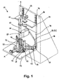
- a winding machine 10 shown in FIGS. 1 to 8 is for winding multipole stators 12 are provided.
- Stator 12 consists essentially of an annular body 14 with from this radially inwardly protruding pole horn 16 through gaps are arranged separately from one another in the form of axial grooves 18. Three windings 20 have already taken place.
- the 15-pole stator 12 shown as an example is part of an internal rotor electronic motor.
- the stator 12 is die cut packaged manufactured from identical sheet metal lamellae to a sheet metal package.
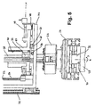
- the stator 12 is in during the winding process a clamping device 22 fixed.
- One rotatably supported in a transport pallet 24 Shaft 26 is rigidly connected to the clamping device 22.
- the free end of the Shaft 26 is in the winding position via a driver 30 with a switching device 28 connected.
- the switching device 28 is used to perform a rotary movement the stator 12 about its axis of rotation z.
- the transport pallet 24 becomes a winding machine via a pallet conveyor 84 by means of conveyor belts 82 10 out and out of this again.
- a winding rod 32 with a wire guide nozzle 34 is arranged in a vertically arranged vertical guide rail lying parallel to the axis of rotation z of the stator 12 40 sliding.
- the wire guide nozzle 34 is at the lower end of the Wrapping arm 32 fixed and has with respect to the stator 12 and its axis of rotation z radially outwards.
- the upper part of the winding rod 32 is a wire guide tube 38 trained.
- the winding wire 36 is over the wire guide tube 38 Wire guide nozzle 34 supplied.
- the vertical guide rail 40 is part of an adjustment block 42, which on a radial stationary guide rail 44 in a radial axis of displacement x in the direction of that corresponding to the axis of rotation of the stator vertical axis z is displaceable.
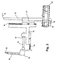
- the adjustment block 42 is in a a first threaded spindle 46 mounted on a thread 48 in the adjusting block 42 the radial guide rail 44 slidably.
- the first threaded spindle 46 is via a deflection gear 50 with a flexible shaft mounted in a casing 54 52 connected.
- each the flexible shafts 52 (in the drawing only one flexible shaft is shown is connected to a central first drive motor 56.
- a bearing block 58 is a displaceable in the vertical axis z Lift rod 60 stored.
- the lifting rod 60 For carrying out lifting movements in the axis direction z is the lifting rod 60 at its upper end as a second threaded spindle 62 formed, which with a second drive motor 64 for executing the stroke the lifting rod 60 is connected.
- bracket parts 66 At the lower end of the lifting rod 60 are horizontally projecting bracket parts 66 with an elongated hole likewise extending in the radial direction x 68 arranged.
- the slot 68 is used to accommodate the side of the Winding rod 32 attached guide pin 70.
- the radial guide rails 44 for the adjusting blocks 42 are on a first one Platform 72 mounted.
- This platform 72 has a central opening 73.
- the vertical guide rails 40 and the slidable therein Winding rods 32 pass through the opening 73.
- the two drive motors 56, 64 are on a second platform arranged above the first platform 72 74 mounted.
- the two platforms 72, 74 are connected to a rear wall 76 which is the bearing block 58 for the lifting rod 60, to each other in Kept clear.
- the arrangement consisting of the two platforms 72, 74 and the rear wall 76 is on a mounting wall via third guide rails 78 80 slidably attached in the vertical direction.
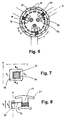
- FIG. 8 shows the displacement movements of the wire guide nozzle 34 in the horizontal direction x. These displacement movements result from the sliding displacement of the adjustment blocks 42 along the radial guide rails 44.
- a first displacement movement v 1 takes place radially outward with respect to the axis of rotation z
- a second displacement movement v 2 is opposite to the first displacement movement v 1 .
- the displacement movements v 1 , 2 are superimposed on the lifting and switching movements h 1 , 2 and e 1 , 2, which are carried out perpendicularly thereto. They take place according to the winding speed to achieve even winding layers continuously or step by step to build up a winding layer radially outwards (v 1 ) and for the subsequent winding of the next layer radially inwards (v 2 ).
- FIGS. 1 to 8 is a winding machine for the winding of stators for internal rotor motors shows from the consideration of the drawing also the use the winding machine for winding stators for external rotor motors.
- the functional mode of operation of the individual machine elements remains the same, only their arrangement and orientation with respect to the stator to be wound must be adapted.
- Every stator is one Associated winding rod with a wire guide.
- the parallel to each other Winding bars with wire guides are also common Lift rod operatively connected.
Landscapes
- Engineering & Computer Science (AREA)
- Manufacturing & Machinery (AREA)
- Power Engineering (AREA)
- Manufacture Of Motors, Generators (AREA)
Description
- der Drahtführer zur Ausführung einer ersten Verschiebebewegung in vertikaler Richtung mit einer axial in vertikaler Richtung verschiebbaren Hubstange wirkverbunden ist,
- ein Schaltapparat zur Ausführung einer zweiten Verschiebe- bzw. Drehbewegung in horizontaler Richtung mit dem zu bewickelnden Stator wirkverbunden ist, und
- der Drahtführer zur Ausführung der Verschiebebewegung in der Längsrichtung des zu umwickelnden Polhornes entsprechender radialer Richtung mit einer in radialer Richtung verschiebbaren Wickelstange verbunden ist,
- Fig. 1 eine Schrägsicht auf eine Wickelmaschine;
- Fig. 2 eine Schrägsicht auf ein Detail von Fig. 1;
- Fig. 3 eine Seitenansicht einer Verstelleinheit für eine Drahtführerdüse von Fig. 1 in vergrösserter Darstellung;
- Fig. 4 eine Schrägsicht auf die Wickelmaschine von Fig. 1 mit einer Paletten-Transporteinheit;
- Fig. 5 eine Seitenansicht eines Details von Fig. 4;
- Fig. 6 eine Ansicht von unten auf ein Detail von Fig. 1;
- Fig. 7,8 Darstellung der Relativbewegungen einer Drahtführerdüse während eines Wickelvorganges.
- Erste Hubbewegung h1 in vertikaler Richtung nach oben, ausgeführt durch eine entsprechende Hubbewegung der Hubstange 60
- Erste Schaltbewegung e1 in horizontaler Richtung, ausgeführt durch eine entsprechende Schaltbewegung des Schaltapparates 28 in seiner Drehrichtung
- Zweite Hubbewegung h2 vertikale nach unten, ausgeführt durch eine entsprechende Hubbewegung der hubstange 60
- Zweite Schaltbewegung e2 in entgegengesetzter horizontaler Richtung, ausgeführt durch eine entsprechende Schaltbewegung des Schaltapparates 28.
Claims (11)
- Vonrichtung zum gleichzeitigen Wickeln von Draht (36) um Polhörner (16) wenigstens eines mehrpoligen rotationssymmetrischen Stators (12) einer elektrischen Maschine, mit mehreren Drahtführen (34) zur Ausgabe des Drahtes (36) und zur Ausführung einer aus Einzelbewegungen zusammengesetzten Wickelbewegung um das zu umwickelnde Polhom (16) und einer Verschiebebewegung in Längsrichtung des Polhornes (16), wobeian der Hubstange (60) für jede Wickelstange (32) je ein Halterungsteil (66) mit einem in radialer Richtung (x) liegenden Langloch (68) angeordnet und ein an jeder Wickelstange (32) festgelegter Führungsbolzen (70) im Langloch (68) geführt ist.jeder Drahtführer (34) zur Ausführung einer ersten Verschiebebewegung in vertikaler Richtung (z) mit einer axial in vertikaler Richtung (z) verschiebbaren Hubstange (60) wirkverbunden ist,je ein Schaltapparat (28) zur Ausführung einer zweiten Verschiebe- bzw. Drehbewegung in horizontaler Richtung (y) mit je einem bewickelnden Stator (12) wirkverbunden ist, undjeder Drahtführer (34) zur Ausführung der Verschiebebewegung in der Längsrichtung des zu umwickelnden Polhornes (16) entsprechender radialer Richtung (x) mit je einer in radialer Richtung (x) verschiebbaren Wickelstange (32) verbunden ist, wobei
- Vorrichtung nach Anspruch 1, dadurch gekennzeichnet, dass jede Wickelstange (32) über eine Radialführung (44) in radialer Richtung (x) verschiebbar ist.
- Vorrichtung nach Anspruch 2, dadurch gekennzeichnet, dass zur Ausführung der Verschiebebewegung in radialer Richtung (x) eine erste Gewindespindel (46) angeordnet ist.
- Vorrichtung nach Anspruch 3, dadurch gekennzeichnet, dass jede erste Gewindespindel (46) über eine vorzugsweise biegsame Welle (52) mit einem gemeinsamen ersten Antriebsmotor (56) verbunden ist.
- Vorrichtung nach einem der Ansprüche 2 bis 4, dadurch gekennzeichnet, dass jede Wickelstange (32) an einem entlang der Radialführung (44) verschiebbaren Verstellblock (42) festgelegt ist.
- Vorrichtung nach Anspruch 5, dadurch gekennzeichnet, dass jede Wickelstange (32) entlang einer am Verstellblock (42) angeordneten Vertikalführung (40) in vertikaler Richtung (z) verschiebbar ist und die erste Gewindespindel (46) am Verstellblock (42) angreift.
- Vorrichtung nach einem der Ansprüche 1 bis 6, dadurch gekennzeichnet, dass die Hubstange (60) vorzugsweise über eine zweite Gewindespindel (62) mit einem zweiten Antriebsmotor (64) verbunden ist.
- Vorrichtung nach einem der Ansprüche 1 bis 7, dadurch gekennzeichnet, dass jeder Schaltapparat (28) während des Wickelvorganges mit einer Spannvorrichtung (22) für den zu bewickelnden Stator (12) verbunden ist.
- Verwendung der Vorrichtung nach einem der Ansprüche 1 bis 8 zum gleichzeitigen Umwickeln mehrerer Polhörner (16) eines Stators (12).
- Verwendung der Vorrichtung nach einem der Ansprüche 1 bis 8 zum gleichzeitigen Umwickeln jeweils eines Polhornes (16) mehrerer Statoren (12).
- Verwendung nach Anspruch 10, dadurch gekennzeichnet, dass die Wickelstangen (32) parallel zueinander und in Linie angeordnet sind.
Priority Applications (1)
| Application Number | Priority Date | Filing Date | Title |
|---|---|---|---|
| EP20020405612 EP1286452B1 (de) | 2001-08-06 | 2002-07-17 | Vorrichtung zum Wickeln eines mehrpoligen Stators |
Applications Claiming Priority (3)
| Application Number | Priority Date | Filing Date | Title |
|---|---|---|---|
| EP01810760 | 2001-08-06 | ||
| EP01810760A EP1283585A1 (de) | 2001-08-06 | 2001-08-06 | Vorrichtung zum Wickeln eines mehrpoligen Stators |
| EP20020405612 EP1286452B1 (de) | 2001-08-06 | 2002-07-17 | Vorrichtung zum Wickeln eines mehrpoligen Stators |
Publications (2)
| Publication Number | Publication Date |
|---|---|
| EP1286452A1 EP1286452A1 (de) | 2003-02-26 |
| EP1286452B1 true EP1286452B1 (de) | 2004-09-08 |
Family
ID=26077410
Family Applications (1)
| Application Number | Title | Priority Date | Filing Date |
|---|---|---|---|
| EP20020405612 Expired - Lifetime EP1286452B1 (de) | 2001-08-06 | 2002-07-17 | Vorrichtung zum Wickeln eines mehrpoligen Stators |
Country Status (1)
| Country | Link |
|---|---|
| EP (1) | EP1286452B1 (de) |
Cited By (1)
| Publication number | Priority date | Publication date | Assignee | Title |
|---|---|---|---|---|
| DE102008013035A1 (de) * | 2008-03-07 | 2009-09-17 | Minebea Co., Ltd. | Verfahren zum Bewickeln eines Stators für eine Innenläufermaschine und Stator für eine Innenläufermaschine |
Families Citing this family (5)
| Publication number | Priority date | Publication date | Assignee | Title |
|---|---|---|---|---|
| EP1467466A3 (de) * | 2003-04-11 | 2007-04-11 | ATS Wickel- und Montagetechnik AG | Stator einer elektrischen Maschine sowie Verfahren und Vorrichtung zum Wicklen des Stators |
| ATE435515T1 (de) | 2006-12-22 | 2009-07-15 | Ats Wickel Und Montagetechnik | Vorrichtung zum wickeln von statoren von elektromotoren |
| EP1990899B1 (de) | 2007-05-11 | 2017-07-12 | SMZ Wickel- und Montagetechnik AG | Vorrichtung zum Wickeln von Statoren von Elektromotoren |
| DE102022134579A1 (de) * | 2022-12-22 | 2024-06-27 | Aumann Espelkamp Gmbh | Wickelmaschine und Verfahren für das Herstellen von Spulenwicklungen an einem außengenuteten Wicklungsträger eines Rotors oder Stators einer elektrischen Maschine sowie Wickelanlage |
| DE102024129614A1 (de) * | 2024-10-14 | 2026-04-16 | Schaeffler Technologies AG & Co. KG | Vorrichtung und Verfahren Vorrichtung zum Bewickeln eines Rotors oder Stators sowie Fertigungszelle |
Family Cites Families (5)
| Publication number | Priority date | Publication date | Assignee | Title |
|---|---|---|---|---|
| JPS60237837A (ja) * | 1984-05-09 | 1985-11-26 | Sanyo Denki Kk | 巻線機 |
| JPH10271774A (ja) * | 1997-03-28 | 1998-10-09 | Nittoku Eng Co Ltd | 巻線機 |
| JP4252656B2 (ja) * | 1999-02-22 | 2009-04-08 | 三工機器株式会社 | ステータコアへの巻線装置 |
| JP3451033B2 (ja) * | 1999-04-28 | 2003-09-29 | 日特エンジニアリング株式会社 | 巻線装置 |
| JP3432452B2 (ja) * | 1999-05-10 | 2003-08-04 | 三菱電機株式会社 | 巻線機 |
-
2002
- 2002-07-17 EP EP20020405612 patent/EP1286452B1/de not_active Expired - Lifetime
Cited By (1)
| Publication number | Priority date | Publication date | Assignee | Title |
|---|---|---|---|---|
| DE102008013035A1 (de) * | 2008-03-07 | 2009-09-17 | Minebea Co., Ltd. | Verfahren zum Bewickeln eines Stators für eine Innenläufermaschine und Stator für eine Innenläufermaschine |
Also Published As
| Publication number | Publication date |
|---|---|
| EP1286452A1 (de) | 2003-02-26 |
Similar Documents
| Publication | Publication Date | Title |
|---|---|---|
| DE60023785T2 (de) | Wickelmaschine | |
| DE3625193A1 (de) | Maschinentisch | |
| DE4234675C2 (de) | Zweidimensionales Antriebssystem | |
| AT520311B1 (de) | Verfahren und Vorrichtung zur automatisierten Herstellung eines Stators einer elektrischen Maschine | |
| DE2316078A1 (de) | Staenderwickelmaschine | |
| DE2821552C2 (de) | Elektronische Nähmaschine | |
| DE2661121C2 (de) | ||
| DE2215444C2 (de) | Vorrichtung zum Wickeln von axial in einen Stator einer dynamoelektrischen Maschine einziehbaren Spulen | |
| DE2854351C2 (de) | Verfahren zur Herstellung verseilter Drahterzeugnisse mit abwechselnder Schlagrichtung und Verseilmaschine zur Ausführung desselben | |
| EP0604797B1 (de) | Verfahren und Vorrichtung zur Herstellung einer Wellenwicklung, insbesondere für Drehstromgeneratoren | |
| EP1759446B1 (de) | Wickelvorrichtung | |
| EP1283585A1 (de) | Vorrichtung zum Wickeln eines mehrpoligen Stators | |
| EP1936784A1 (de) | Vorrichtung zum Wickeln von Statoren von Elektromotoren | |
| EP1286452A1 (de) | Vorrichtung zum Wickeln eines mehrpoligen Stators | |
| DE60311955T2 (de) | Apparat und Verfahren zur Herstellung einer Mehrleiter-Wicklung | |
| EP1566243B1 (de) | Vorrichtung zum Positionieren und Antreiben eines Arbeitswerkzeuges | |
| EP3707731B1 (de) | Verdrillvorrichtung und verdrillkopfeinrichtung sowie verfahren zum verdrillen oder verseilen von leitungen | |
| EP1079222B1 (de) | Verfahren und Vorrichtung zum Unwuchtsausgleich durch Materialentfernung | |
| DE2645598A1 (de) | Federwickler oder dergleichen | |
| DE3803785A1 (de) | Elementengruppe fuer den antrieb des aufspanntisches einer automatischen verzahnungsmaschine | |
| DE102006032443B4 (de) | Vorrichtung zum Positionieren und Adapter zum Anschließen eines Werkzeugs oder eines Werkstücks | |
| DE102023104359B4 (de) | Wickelvorrichtung und Verfahren zum Herstellen einer Anordnung für eine elektrische Maschine | |
| DE2710442C2 (de) | Ringspinnmaschine mit einer verfahrbaren, automatischen Wartungsvorrichtung zum selbsttätigen Beheben von Fadenbrüchen | |
| DE2018813B2 (de) | Verfahren zum Herstellen von Anschlüssen an elektrischen Spulen und Vorrichtung zur Durchführung des Verfahrens | |
| DE102025113047A1 (de) | Wickelmaschine |
Legal Events
| Date | Code | Title | Description |
|---|---|---|---|
| PUAI | Public reference made under article 153(3) epc to a published international application that has entered the european phase |
Free format text: ORIGINAL CODE: 0009012 |
|
| AK | Designated contracting states |
Kind code of ref document: A1 Designated state(s): AT BE BG CH CY CZ DE DK EE ES FI FR GB GR IE IT LI LU MC NL PT SE SK TR |
|
| AX | Request for extension of the european patent |
Extension state: AL LT LV MK RO SI |
|
| 17P | Request for examination filed |
Effective date: 20030118 |
|
| 17Q | First examination report despatched |
Effective date: 20030331 |
|
| AKX | Designation fees paid |
Designated state(s): CH DE IT LI |
|
| GRAP | Despatch of communication of intention to grant a patent |
Free format text: ORIGINAL CODE: EPIDOSNIGR1 |
|
| GRAS | Grant fee paid |
Free format text: ORIGINAL CODE: EPIDOSNIGR3 |
|
| GRAA | (expected) grant |
Free format text: ORIGINAL CODE: 0009210 |
|
| AK | Designated contracting states |
Kind code of ref document: B1 Designated state(s): CH DE IT LI |
|
| REG | Reference to a national code |
Ref country code: CH Ref legal event code: EP |
|
| REG | Reference to a national code |
Ref country code: IE Ref legal event code: FG4D Free format text: GERMAN |
|
| REF | Corresponds to: |
Ref document number: 50200947 Country of ref document: DE Date of ref document: 20041014 Kind code of ref document: P |
|
| REG | Reference to a national code |
Ref country code: CH Ref legal event code: NV Representative=s name: PATENTANWAELTE BREITER + WIEDMER AG |
|
| REG | Reference to a national code |
Ref country code: IE Ref legal event code: FD4D |
|
| PLBE | No opposition filed within time limit |
Free format text: ORIGINAL CODE: 0009261 |
|
| STAA | Information on the status of an ep patent application or granted ep patent |
Free format text: STATUS: NO OPPOSITION FILED WITHIN TIME LIMIT |
|
| 26N | No opposition filed |
Effective date: 20050609 |
|
| REG | Reference to a national code |
Ref country code: CH Ref legal event code: NV Representative=s name: ISLER & PEDRAZZINI AG |
|
| REG | Reference to a national code |
Ref country code: CH Ref legal event code: PCAR Free format text: ISLER & PEDRAZZINI AG;POSTFACH 1772;8027 ZUERICH (CH) |
|
| PGFP | Annual fee paid to national office [announced via postgrant information from national office to epo] |
Ref country code: CH Payment date: 20110728 Year of fee payment: 10 |
|
| PGFP | Annual fee paid to national office [announced via postgrant information from national office to epo] |
Ref country code: DE Payment date: 20110722 Year of fee payment: 10 |
|
| PGFP | Annual fee paid to national office [announced via postgrant information from national office to epo] |
Ref country code: IT Payment date: 20110726 Year of fee payment: 10 |
|
| REG | Reference to a national code |
Ref country code: CH Ref legal event code: PL |
|
| PG25 | Lapsed in a contracting state [announced via postgrant information from national office to epo] |
Ref country code: CH Free format text: LAPSE BECAUSE OF NON-PAYMENT OF DUE FEES Effective date: 20120731 Ref country code: LI Free format text: LAPSE BECAUSE OF NON-PAYMENT OF DUE FEES Effective date: 20120731 Ref country code: DE Free format text: LAPSE BECAUSE OF NON-PAYMENT OF DUE FEES Effective date: 20130201 |
|
| REG | Reference to a national code |
Ref country code: DE Ref legal event code: R119 Ref document number: 50200947 Country of ref document: DE Effective date: 20130201 |
|
| PG25 | Lapsed in a contracting state [announced via postgrant information from national office to epo] |
Ref country code: IT Free format text: LAPSE BECAUSE OF NON-PAYMENT OF DUE FEES Effective date: 20120717 |