EP1286444A2 - Vorrichtung zum gleichberechtigten Parallelbetrieb von ein- oder dreiphasigen Spannungsquellen - Google Patents
Vorrichtung zum gleichberechtigten Parallelbetrieb von ein- oder dreiphasigen Spannungsquellen Download PDFInfo
- Publication number
- EP1286444A2 EP1286444A2 EP02018526A EP02018526A EP1286444A2 EP 1286444 A2 EP1286444 A2 EP 1286444A2 EP 02018526 A EP02018526 A EP 02018526A EP 02018526 A EP02018526 A EP 02018526A EP 1286444 A2 EP1286444 A2 EP 1286444A2
- Authority
- EP
- European Patent Office
- Prior art keywords
- voltage
- phase
- frequency
- inverters
- inverter
- Prior art date
- Legal status (The legal status is an assumption and is not a legal conclusion. Google has not performed a legal analysis and makes no representation as to the accuracy of the status listed.)
- Granted
Links
Images


Classifications
-
- H—ELECTRICITY
- H02—GENERATION; CONVERSION OR DISTRIBUTION OF ELECTRIC POWER
- H02M—APPARATUS FOR CONVERSION BETWEEN AC AND AC, BETWEEN AC AND DC, OR BETWEEN DC AND DC, AND FOR USE WITH MAINS OR SIMILAR POWER SUPPLY SYSTEMS; CONVERSION OF DC OR AC INPUT POWER INTO SURGE OUTPUT POWER; CONTROL OR REGULATION THEREOF
- H02M7/00—Conversion of ac power input into dc power output; Conversion of dc power input into ac power output
- H02M7/42—Conversion of dc power input into ac power output without possibility of reversal
- H02M7/44—Conversion of dc power input into ac power output without possibility of reversal by static converters
- H02M7/48—Conversion of dc power input into ac power output without possibility of reversal by static converters using discharge tubes with control electrode or semiconductor devices with control electrode
- H02M7/493—Conversion of dc power input into ac power output without possibility of reversal by static converters using discharge tubes with control electrode or semiconductor devices with control electrode the static converters being arranged for operation in parallel
Definitions
- the invention relates to a device specified in the preamble of claim 1 Genus.
- inverters which deliver a regulated AC voltage or can set a predetermined AC voltage (usually 50 Hz, 230 V eff ) come into consideration as AC voltage sources .
- These may be single- or three-phase inverters whose output voltages are regulated by a pulse width control and which have their input DC voltages z.
- each inverter requires its own voltage and frequency reference if additional synchronization and / or communication lines are to be dispensed with.
- known references eg quartz oscillators
- Aging effects od errors in current and voltage sensing, temperature dependencies.
- the output voltage of each inverter must be controlled, for which purpose only the time characteristic of its output voltage u and its current i is available.
- each inverter 1.2 with a control device according to Fig. 2.
- the core of such a control means is a unit 6 with two inputs to which the actual values of the voltage u and the current i is the respective inverter, here the inverter 1, are supplied.
- This unit 6 determines, using frequency and voltage statistics, a reference voltage u ref determined according to frequency and amplitude, which serves as a reference variable or desired value in a control circuit 7 for the inverter 1.
- U ref from the comparison between the reference voltage and the respective actual voltage u of the inverter 1 is derived a signal for controlling the respective inverter 1, normally consisting of a control signal for the pulse width.
- a disadvantage of the known device is that they only with relatively flat frequency statistics can be operated due to the tolerances of available quartzes and other devices lead to implementation difficulties and therefore can not be technically implemented. Become realistic, steeper Statics used, then these lead to power oscillations between the parallel switched inverters and thus instabilities, as shown in Fig. 3 by way of example are shown. The active power components oscillate between the inverters and forth and rocking, which makes a practical application impossible.
- the invention is the technical problem underlying the device of Initially designated genus in such a way that comparatively steep statics can be used and still a rocking of the active power components effectively avoided.
- the invention has the surprising advantage that the reference to FIG. 3 explained instabilities by the additional consideration of the phase in the Completely avoid regulation of the inverters. As follows from a preferred embodiment is explained in more detail, are also at Application of comparatively steep frequency or active power statistics already after receive a stationary active power values for a short transient process. This results the main advantage that the Wirk orientalsstatiken more or less arbitrary can be determined.
- the inventive construction 2. contains the unit 6 displays a for generating the reference voltage U ref certain unit 6 of the control device according to Fig.
- a block 8 having two inputs, one input of the signal u (t) and the other input the signal i is supplied to (t).
- the block 8 has two outputs, wherein at one output the signal P of the active power and at the other output the signal Q of the reactive power appears.
- the block 8 in single-phase systems is preferably designed as a known per se, schematically shown in Fig. 5 arrangement (DE 199 49 997 A1), which is used for fast and accurate determination of the values P and Q using special filters. The resulting high measuring speed allows a quick control of the inverters 1 and 2 and avoids the emergence of overcurrents.
- Fig. 5 shows schematically a special filter 10 suitable for the purposes of the invention for providing a signal which is substantially phase-shifted by 90 ° from a first periodic input signal.
- the filter 10 includes an input 11 which is connected via a first summing element 12, a proportional element 14 and a second summing element 15 to the input of a first integrator 16. Its output 17 is fed back via a connection 18 and the first summing element 12 to the input of the proportional element 14.
- the filter 10 has a second integrator 19, which is connected to the first integrator 16, wherein the two integrators 16, 19 form two coupled integrator stages.
- an output 20 of the integrating element 19 leads to the second summing element 15, while conversely the output 17 of the first integrating element 16 is fed back to the input of the second integrating element 19.
- the two integrating stages 16, 19 operate with a gain which corresponds to the circular frequency ⁇ N of the fundamental of the first signal (eg 314 at 50 Hz).
- the filter 10 is arranged so that a sinusoidal input signal, for. B. the voltage u is , at the input 11 in amplitude, frequency and phase coincide substantially with a sinusoidal signal u A at the output 17 of the first integrator 16, if the filter 10 is in the steady state.
- an error signal is produced at the first summing element 12, which is amplified in the proportional element 14 with a preselected factor and then fed to the integrating element 16 via the second summing element 15.
- the amplified error signal is integrated until it is zero due to the negative feedback of the output 17 to the first summer 12 and thus the filter 10 has settled.
- a signal u B at the output 20 of the second integrator 19 results from the integration of the signal u A at the output 17 of the first integrator 16. Since the integration of a sinusoidal signal u A causes a phase shift of substantially 90 °, the signal u B orthogonal to the signal u A , ie substantially equal in amplitude and frequency, but substantially phase shifted by 90 °.
- the Reinforcement factors of the integrators 16, 19 thereby represent the operating frequency of Filters 10 on. In power systems this z. B. 50 Hz. Also be suppressed by the filter effect of the filter 10 possible interference, in particular those, the signals with a deviating from the resonant frequency affect.
- the block 8 has a second, the filter 10 corresponding filter 21 with an input 22 to which the signal i is supplied so that the filter 21 at outputs 23 and 24 two phase-shifted by 90 ° signals i A and I B delivers.
- P and Q 1/2 (u B ⁇ I A + B ⁇ I B )
- the determination of the values P and Q is therefore carried out by connecting the filters 10, 21 to an arithmetic circuit connected to the outputs 17, 20 and 23, 24, respectively. This contains one hand connected to the outputs 17, 23 multiplier element 25, on the other hand, connected to the outputs 20, 24 multiplier 26.
- the P and Q values obtained with the arrangement according to FIG. 5 are respectively supplied to a decoupling network 36, 37, which essentially consists of a first-order delay element.
- These decoupling networks 36, 37 are introduced to decouple the active and reactive power control during current changes faster than a grid period. They are also necessary to keep the frequency and the voltage constant for non-linear loads (eg rectifier) or for unbalanced load in the three-phase case, since the P- or Q-determination in these cases provides pulsating results.
- the chosen names of the delays are intended to illustrate the analogy to a machine.
- the moment of inertia (T mech ) and the excitation time constant (T erreg ) have a similar smoothing effect .
- the size of the delay to be chosen is a compromise between overload capacity of the power converters, which requires instantaneous control to avoid high balancing currents, and desired smoothing for non-linear loads or unbalanced load.
- the thus-delayed P and Q values are supplied respectively to a multiplier 38 and 39, respectively, and multiplied therein by the values St1 and St2 corresponding to the slopes of the statics of Figs. 6 and 7 and hence the dimensions Hz / W or 1 / A.
- the output values 40 represent the adder a frequency reference and the output values of the adder 41 a voltage reference in the form of an absolute amount of the amplitude. From the two values is finally derived u ref in a block 42 which can be seen also from FIG. 2 reference voltage.
- FIG. 6 The frequency statics shown in FIG. 6 indicate the relationship between f and P. Accordingly, FIG. 7 shows the voltage statics, ie the dependence of the reactive power Q on the voltage u.
- FIG. 7 shows the voltage statics, ie the dependence of the reactive power Q on the voltage u.
- Figs. 6 and 7 are used instead of P and Q along the abscissa normalized to the nominal power P N, Q N values indicated. Therefore, z.
- a theoretical change in power P from idle to rated power is a change in frequency of 1% (0.5 Hz), with a positive P at the same time giving active power through the respective inverter 1,2 and a negative P corresponding to a recording of active power by the respective inverter 1.2.
- Fig. 6 a theoretical change in power P from idle to rated power is a change in frequency of 1% (0.5 Hz), with a positive P at the same time giving active power through the respective inverter 1,2 and a negative P corresponding to a
- a theoretical change of the reactive power Q from 0 to Q N means a voltage change of 4%.
- a normalized slope St1 of -0.01 Hz results in FIG. 6 and in FIG. 7 a normalized slope St2 of -0.04 V.
- the reactive power control is analogous with the difference that with the help of Slope St2 an amplitude reference is obtained instead of a frequency reference.
- u ref
- the unit 6 according to FIG. 4 is supplemented by a negative weighting factor St1 'which takes into account the phase ⁇ and which is indicated by the multiplier stage 43.
- St1 ' which takes into account the phase ⁇ and which is indicated by the multiplier stage 43.
- the delayed P value of the active power is multiplied by a factor which supplies a value for the phase ⁇ of the reference voltage u ref . Therefore, u ref is now denoted by f,
- the voltage u.sub.ref is regulated in the inverters 1, 2 with a phase and amplitude-accurate regulation, as is known per se both for the single-phase case [6] and for the three-phase case [7].
- the active power P is defined by the phase ⁇ in inductively coupled inverters
- the consideration of the phase ⁇ according to the invention or the phase precontrol achieved by it acts faster and thus attenuating in the control device.
- the factor St1 ' is negative. Is therefore the Value P at the output of block 8 is positive, which corresponds to a positive phase angle, then, via the multiplier stage 43, a negative ⁇ is obtained, which via the phase precontrol to a reduction of the phase angle and thus to a reduction in the delivered power leads.
- the phase precontrol affects those inverters, record the active power, in the reverse manner to the effect that the active power consumption is reduced.
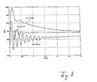
- the factor St1 ' is dependent on the network impedances 4,5 and the slope St1 of the frequency statics z. B. determined by an optimization calculation. This is illustrated by way of example in FIG. 8 at three values for St1 ', which are -0.2 m, -0.4 m and -0.8 m, while, analogously to FIG. 6, a frequency statics of 1% is again used.
- phase precontrol Only the introduction of phase precontrol thus enables stable operation as well with steep frequency statistics. It turns out a stable performance according to the chosen Frequency statics.
- the additional degree of freedom of the phase precontrol allows at given network coupling impedances of the inverter and given, possibly. Technologically conditioned slopes of the frequency statistics setting an appropriate Transient response of the inverter.
- the weight factor St1 'must be for a given slope of Frequency statics and the Netzkoppelindukt society be determined suitably. This can be z. B. done by evaluating the root locus of the supply system.
- the system natural frequency also changes with the phase precontrol and may need to be adjusted so that resonances in the overall system are avoided become.
Abstract
Description
- alle beteiligten Wechselrichter eine identische Frequenz benötigen,
- nur kleine Spannungsdifferenzen zwischen den Wechselrichtern zugelassen sind, und
- die Phasenunterschiede zwischen den Wechselrichtern sehr klein sein müssen.
Claims (5)
- Vorrichtung zum gleichberechtigten Parallelbetrieb von induktiv gekoppelten Wechselrichtern (1,2), die über Netzkoppelimpedanzen (4,5) an eine gemeinsame Versorgungsleitung (3) angeschlossen sind, wobei jeder Wechselrichter (1,2) mit je einem zur Regelung seiner Ausgangsspannung bestimmten Regelkreis (7) versehen ist, dem als Sollspannung eine Referenzspannung (uref) zugeführt wird, deren Frequenz (f) unter Berücksichtigung einer vorgewählten Frequenzstatik aus der Wirkleistung (P) und deren Amplitude (|u|) unter Berücksichtigung einer vorgewählten Spannungsstatik aus der Blindleistung (Q) des betreffenden Wechselrichters (1,2) abgeleitet ist, dadurch gekennzeichnet, daß aus der Wirkleistung (P) unter Berücksichtigung eines vorgewählten Gewichtsfaktors (St1') auch ein Wert für die Phase (ϕ) der Referenzspannung (uref) abgeleitet wird.
- Vorrichtung nach Anspruch 1, dadurch gekennzeichnet, daß der vorgewählte Gewichtsfaktor (St1') bei allen Wechselrichtern (1,2) derselbe ist.
- Vorrichtung nach Anspruch 1 oder 2, dadurch gekennzeichnet, daß der Gewichtsfaktor (St1') durch eine Optimierungsrechnung erhalten wird.
- Vorrichtung nach einem der Ansprüche 1 bis 3, dadurch gekennzeichnet, daß Istwerte der Wirk- und Blindleistung (P, Q) dadurch gewonnen werden, daß aus ersten Signalen (uA, iA), die den Istwerten (uist, iist) der Spannung und des Stroms des betreffenden Wechselrichters (1,2) entsprechen, durch Integration je ein im wesentliches gleiches, jedoch um 90° phasenverschobenes zweites Signal (uB, iB) ermittelt wird und dabei die einen Signale (uA, iA) als Realteile und die anderen Signale (uB, iB) als Imaginärteile von Raumzeigern der Spannung bzw. des Stroms interpretiert werden.
- Vorrichtung nach Anspruch 4, dadurch gekennzeichnet, daß den Istwerten der Wirk- bzw. Blindleistung (P, Q) entsprechenden Ausgängen je ein Entkopplungsnetzwerk (36, 37) nachgeschaltet ist.
Applications Claiming Priority (2)
| Application Number | Priority Date | Filing Date | Title |
|---|---|---|---|
| DE10140783 | 2001-08-21 | ||
| DE10140783A DE10140783A1 (de) | 2001-08-21 | 2001-08-21 | Vorrichtung zum gleichberechtigten Parallelbetrieb von ein- oder dreiphasigen Spannungsquellen |
Publications (3)
| Publication Number | Publication Date |
|---|---|
| EP1286444A2 true EP1286444A2 (de) | 2003-02-26 |
| EP1286444A3 EP1286444A3 (de) | 2005-02-09 |
| EP1286444B1 EP1286444B1 (de) | 2006-10-18 |
Family
ID=7696027
Family Applications (1)
| Application Number | Title | Priority Date | Filing Date |
|---|---|---|---|
| EP02018526A Expired - Lifetime EP1286444B1 (de) | 2001-08-21 | 2002-08-17 | Vorrichtung zum gleichberechtigten Parallelbetrieb von ein- oder dreiphasigen Spannungsquellen |
Country Status (6)
| Country | Link |
|---|---|
| US (1) | US6693809B2 (de) |
| EP (1) | EP1286444B1 (de) |
| JP (2) | JP2003111281A (de) |
| AT (1) | ATE343239T1 (de) |
| DE (2) | DE10140783A1 (de) |
| ES (1) | ES2275787T3 (de) |
Cited By (7)
| Publication number | Priority date | Publication date | Assignee | Title |
|---|---|---|---|---|
| WO2008109265A1 (en) * | 2007-03-01 | 2008-09-12 | Wisconsin Alumni Research Foundation | Inverter based storage in dynamic distribution systems including distributed energy resources |
| WO2008109263A1 (en) * | 2007-03-01 | 2008-09-12 | Wisconsin Alumni Research Foundation | Non-inverter based distributed energy resource for use in a dynamic distribution system |
| US7920942B2 (en) | 2007-03-01 | 2011-04-05 | Wisconsin Alumni Research Foundation | Control of combined storage and generation in distributed energy resources |
| WO2011085961A2 (de) * | 2010-01-12 | 2011-07-21 | Skywind Gmbh | Verfahren und vorrichtung zum aufsynchronisieren eines generators in einem netz |
| CN105634310A (zh) * | 2014-11-06 | 2016-06-01 | 台达电子工业股份有限公司 | 控制信号产生系统及其逆变器控制装置与相关控制电路 |
| US9831678B2 (en) | 2013-03-14 | 2017-11-28 | Sma Solar Technology Ag | Method for black starting a power station comprising a plurality of inverters connectable to an AC electrical grid |
| CN110311397A (zh) * | 2019-07-26 | 2019-10-08 | 国网湖南省电力有限公司 | 基于自适应识别的储能电站多场景协同控制方法 |
Families Citing this family (28)
| Publication number | Priority date | Publication date | Assignee | Title |
|---|---|---|---|---|
| TWI286413B (en) * | 2005-05-27 | 2007-09-01 | Delta Electronics Inc | Parallel inverters and controlling method thereof |
| US7680562B2 (en) * | 2005-09-08 | 2010-03-16 | General Electric Company | Power generation system |
| CN100488017C (zh) * | 2005-12-15 | 2009-05-13 | 中国科学院电工研究所 | 消除逆变器并联运行系统中直流环流的装置 |
| JP4846450B2 (ja) * | 2006-05-23 | 2011-12-28 | 三菱電機株式会社 | インバータ電源制御装置 |
| DE102006027716B3 (de) | 2006-06-15 | 2008-01-24 | Lenze Drive Systems Gmbh | Ansteuerung mit Wechselrichtern bei geringen Schaltverlusten |
| EP1995656A1 (de) | 2007-05-23 | 2008-11-26 | SMA Solar Technology AG | Verfahren zur Leistungsanpassung |
| DE102008017715A1 (de) * | 2008-04-02 | 2009-10-15 | Nordex Energy Gmbh | Verfahren zum Betreiben einer Windenergieanlage mit einer doppelt gespeisten Asynchronmaschine sowie Windenergieanlage mit einer doppelt gespeisten Asynchronmaschine |
| US7804184B2 (en) * | 2009-01-23 | 2010-09-28 | General Electric Company | System and method for control of a grid connected power generating system |
| DE102009042865A1 (de) | 2009-04-16 | 2011-05-19 | Kühn, Walter, Prof. Dr. Ing. | Verfahren und Vorrichtung zur automatischen Stabilisierung eines Netzes die für elektrische Energieversorgung mit zumindest einem Stromrichter |
| US8418418B2 (en) | 2009-04-29 | 2013-04-16 | 3Form, Inc. | Architectural panels with organic photovoltaic interlayers and methods of forming the same |
| US7990743B2 (en) * | 2009-10-20 | 2011-08-02 | General Electric Company | System and method for decreasing solar collector system losses |
| US7855906B2 (en) * | 2009-10-26 | 2010-12-21 | General Electric Company | DC bus voltage control for two stage solar converter |
| US8050062B2 (en) * | 2010-02-24 | 2011-11-01 | General Electric Company | Method and system to allow for high DC source voltage with lower DC link voltage in a two stage power converter |
| US20140049229A1 (en) | 2011-03-11 | 2014-02-20 | Siemens Aktiengesellschaft | Power generation unit driver, power generation unit and energy output equipment in power grid |
| CN102244498B (zh) * | 2011-03-11 | 2013-09-18 | 西门子公司 | 一种电网中的发电单元驱动器、发电单元以及能量输出设备 |
| CN104011959B (zh) | 2011-12-16 | 2017-03-22 | 南威斯特法伦大学 | 带分散电源系统的电源网格中频率和电压的主动控制方法 |
| DE102011121707A1 (de) * | 2011-12-20 | 2013-07-04 | Airbus Operations Gmbh | Elektrisches System für ein Luftfahrzeug |
| US9362845B2 (en) | 2013-12-23 | 2016-06-07 | Generac Power Systems, Inc. | Method of operating a single-phase generator in parallel with an inventor |
| US9762160B2 (en) | 2013-12-23 | 2017-09-12 | Generac Power Systems, Inc. | Method of controlling multiple parallel-connected generators |
| DE102016203123A1 (de) | 2016-02-26 | 2017-08-31 | Fraunhofer-Gesellschaft zur Förderung der angewandten Forschung e.V. | Vorrichtung und Verfahren zur Regelung eines Wechselrichters |
| JP6724505B2 (ja) * | 2016-04-07 | 2020-07-15 | 富士電機株式会社 | 船舶用陸上電源システム及び船舶への給電方法 |
| DE102017114306B4 (de) | 2017-06-28 | 2019-01-17 | Sma Solar Technology Ag | Verfahren zum betrieb eines inselnetzes und inselnetz |
| AU2018366935B2 (en) | 2017-11-16 | 2024-03-21 | Sma Solar Technology Ag | Feeding electric power from a photovoltaic system into an AC system having a low short-circuit capacity |
| DE102018133641A1 (de) | 2018-12-27 | 2020-07-02 | Sma Solar Technology Ag | Elektrolysevorrichtung mit einem umrichter und verfahren zur bereitstellung von momentanreserveleistung für ein wechselspannungsnetz |
| DE102019116254B4 (de) * | 2019-06-14 | 2021-05-12 | Sma Solar Technology Ag | Verfahren zum Betrieb einer Energieerzeugungsanlage |
| EP3932732A1 (de) * | 2020-07-03 | 2022-01-05 | ABB Schweiz AG | Stromversorgungsvorrichtung zur speisung einer stromleitung |
| DE102020119039A1 (de) | 2020-07-17 | 2022-01-20 | Sma Solar Technology Ag | Verfahren zum betrieb einer energieversorgungsanlage und energieversorgungsanlage |
| DE102022119897A1 (de) | 2022-08-08 | 2024-02-08 | Sma Solar Technology Ag | Spannungsstellender wechselrichter und energieerzeugungsanlage |
Citations (1)
| Publication number | Priority date | Publication date | Assignee | Title |
|---|---|---|---|---|
| US6169679B1 (en) * | 2000-03-21 | 2001-01-02 | Ford Motor Company | Method and system for synchronizing the phase angles of parallel connected inverters |
Family Cites Families (11)
| Publication number | Priority date | Publication date | Assignee | Title |
|---|---|---|---|---|
| US3852655A (en) * | 1971-05-18 | 1974-12-03 | Hewlett Packard Co | High efficiency power supply |
| US3978393A (en) * | 1975-04-21 | 1976-08-31 | Burroughs Corporation | High efficiency switching regulator |
| US4313155A (en) * | 1980-01-14 | 1982-01-26 | General Electric Company | High input voltage DC to DC power converter |
| JPS6130967A (ja) * | 1984-07-19 | 1986-02-13 | Meidensha Electric Mfg Co Ltd | インバ−タの並列運転装置 |
| JPS61102129A (ja) * | 1984-10-25 | 1986-05-20 | 株式会社明電舎 | インバ−タ装置の並列運転方法 |
| JP2703367B2 (ja) * | 1989-09-29 | 1998-01-26 | 株式会社東芝 | インバータの並列制御装置 |
| US5436512A (en) * | 1992-09-24 | 1995-07-25 | Exide Electronics Corporation | Power supply with improved circuit for harmonic paralleling |
| US5875103A (en) * | 1995-12-22 | 1999-02-23 | Electronic Measurements, Inc. | Full range soft-switching DC-DC converter |
| US6118680A (en) | 1999-05-28 | 2000-09-12 | Peco Ii | Methods and apparatus for load sharing between parallel inverters in an AC power supply |
| US6031747A (en) * | 1999-08-02 | 2000-02-29 | Lockheed Martin Missiles & Space Company | Interleaved synchronous flyback converter with high efficiency over a wide operating load range |
| DE19949997B4 (de) | 1999-10-15 | 2005-08-04 | Institut für Solare Energieversorgungstechnik (ISET) Verein an der Universität Gesamthochschule Kassel eV | Vorrichtung zur Bestimmung der Wirk-und/oder Blindleistung in einem einphasigen elektrischen Wechselspannungssystem und deren Anwendung |
-
2001
- 2001-08-21 DE DE10140783A patent/DE10140783A1/de not_active Withdrawn
-
2002
- 2002-08-16 US US10/222,310 patent/US6693809B2/en not_active Expired - Lifetime
- 2002-08-17 ES ES02018526T patent/ES2275787T3/es not_active Expired - Lifetime
- 2002-08-17 AT AT02018526T patent/ATE343239T1/de active
- 2002-08-17 EP EP02018526A patent/EP1286444B1/de not_active Expired - Lifetime
- 2002-08-17 DE DE50208480T patent/DE50208480D1/de not_active Expired - Lifetime
- 2002-08-21 JP JP2002240991A patent/JP2003111281A/ja not_active Withdrawn
-
2009
- 2009-12-24 JP JP2009291776A patent/JP5383474B2/ja not_active Expired - Fee Related
Patent Citations (1)
| Publication number | Priority date | Publication date | Assignee | Title |
|---|---|---|---|---|
| US6169679B1 (en) * | 2000-03-21 | 2001-01-02 | Ford Motor Company | Method and system for synchronizing the phase angles of parallel connected inverters |
Non-Patent Citations (3)
| Title |
|---|
| IRAVANI M R ET AL: "APPLICATIONS OF STATIC PHASE SHIFTERS IN POWER SYSTEMS" IEEE TRANSACTIONS ON POWER DELIVERY, IEEE INC. NEW YORK, US, Bd. 9, Nr. 3, 1. Juli 1994 (1994-07-01), Seiten 1600-1608, XP000484999 ISSN: 0885-8977 * |
| JENSEN U B ET AL: "Sharing of nonlinear load in parallel connected three-phase converters" CONFERENCE RECORD OF THE 2000 IEEE INDUSTRY APPLICATIONS CONFERENCE. THIRTY-FIFTH IAS ANNUAL MEETING AND WORLD CONFERENCE ON INDUSTRIAL APPLICATIONS OF ELECTRICAL ENERGY, Bd. 4, 8. Oktober 2000 (2000-10-08), Seiten 2338-2344, XP010522583 * |
| TULADHAR A ET AL: "Parallel operation of single phase inverter modules with no control interconnections" APPLIED POWER ELECTRONICS CONFERENCE AND EXPOSITION, 1997. APEC '97 CONFERENCE PROCEEDINGS 1997., TWELFTH ANNUAL ATLANTA, GA, USA 23-27 FEB. 1997, NEW YORK, NY, USA,IEEE, US, 23. Februar 1997 (1997-02-23), Seiten 94-100, XP010215806 ISBN: 0-7803-3704-2 * |
Cited By (13)
| Publication number | Priority date | Publication date | Assignee | Title |
|---|---|---|---|---|
| WO2008109265A1 (en) * | 2007-03-01 | 2008-09-12 | Wisconsin Alumni Research Foundation | Inverter based storage in dynamic distribution systems including distributed energy resources |
| WO2008109263A1 (en) * | 2007-03-01 | 2008-09-12 | Wisconsin Alumni Research Foundation | Non-inverter based distributed energy resource for use in a dynamic distribution system |
| US7787272B2 (en) | 2007-03-01 | 2010-08-31 | Wisconsin Alumni Research Foundation | Inverter based storage in dynamic distribution systems including distributed energy resources |
| US7920942B2 (en) | 2007-03-01 | 2011-04-05 | Wisconsin Alumni Research Foundation | Control of combined storage and generation in distributed energy resources |
| WO2011085961A2 (de) * | 2010-01-12 | 2011-07-21 | Skywind Gmbh | Verfahren und vorrichtung zum aufsynchronisieren eines generators in einem netz |
| WO2011085961A3 (de) * | 2010-01-12 | 2012-04-05 | Skywind Gmbh | Verfahren und vorrichtung zum aufsynchronisieren eines generators in einem netz |
| US9831678B2 (en) | 2013-03-14 | 2017-11-28 | Sma Solar Technology Ag | Method for black starting a power station comprising a plurality of inverters connectable to an AC electrical grid |
| EP3018816A3 (de) * | 2014-11-06 | 2016-06-15 | Delta Electronics, Inc. | Wirk- und blindleistungsregelung für wechselrichter |
| US9705419B2 (en) | 2014-11-06 | 2017-07-11 | Delta Electronics, Inc. | Control signal generating system and inverter control device thereof for improving grid stability |
| CN105634310A (zh) * | 2014-11-06 | 2016-06-01 | 台达电子工业股份有限公司 | 控制信号产生系统及其逆变器控制装置与相关控制电路 |
| CN105634310B (zh) * | 2014-11-06 | 2018-09-04 | 台达电子工业股份有限公司 | 控制信号产生系统及其逆变器控制装置与相关控制电路 |
| CN110311397A (zh) * | 2019-07-26 | 2019-10-08 | 国网湖南省电力有限公司 | 基于自适应识别的储能电站多场景协同控制方法 |
| CN110311397B (zh) * | 2019-07-26 | 2021-07-02 | 国网湖南省电力有限公司 | 基于自适应识别的储能电站多场景协同控制方法 |
Also Published As
| Publication number | Publication date |
|---|---|
| ES2275787T3 (es) | 2007-06-16 |
| EP1286444B1 (de) | 2006-10-18 |
| JP2010110209A (ja) | 2010-05-13 |
| EP1286444A3 (de) | 2005-02-09 |
| DE50208480D1 (de) | 2006-11-30 |
| ATE343239T1 (de) | 2006-11-15 |
| US20030039132A1 (en) | 2003-02-27 |
| JP5383474B2 (ja) | 2014-01-08 |
| JP2003111281A (ja) | 2003-04-11 |
| DE10140783A1 (de) | 2003-04-03 |
| US6693809B2 (en) | 2004-02-17 |
Similar Documents
| Publication | Publication Date | Title |
|---|---|---|
| EP1286444B1 (de) | Vorrichtung zum gleichberechtigten Parallelbetrieb von ein- oder dreiphasigen Spannungsquellen | |
| EP2614573B1 (de) | Verfahren zur stabilisierung eines elektrischen versorgungsnetzes | |
| EP2059999B1 (de) | Verfahren zur regelung von wechselrichtern | |
| EP0144556B1 (de) | Blindleistungskompensator zur Kompensation einer Blindstromkomponente in einem Wechselspannungsnetz | |
| DE3025100A1 (de) | Verstaerker | |
| DE3027725A1 (de) | Regelschaltung fuer einen stromrichter | |
| DE3027724A1 (de) | Verfahren zum regeln des leistungsflusses zwischen einer elektrochemischen zelle und einem stromversorgungsnetz | |
| DE112016003814B4 (de) | Leistungsverteilung für Gleichstrom-Mikronetze | |
| DE3917337A1 (de) | Vorrichtung mit mehreren parallel betriebenen wechselrichtern | |
| EP2766980B1 (de) | Konverter in dreieckskonfiguration | |
| DE202012012968U1 (de) | Dynamische Leistungsfaktorkorrektur und dynamische Steuerung für einen Umformer in einer Stromversorgung | |
| DE102014111006A1 (de) | Leistungswandlungssystem und-verfahren | |
| DE3602496C2 (de) | ||
| DE102021101836B4 (de) | Netzgekoppelter wechselrichter und verfahren zur verringerung von schwankungen der netzfrequenz | |
| EP2632012A1 (de) | Verfahren zum Synchronisieren einer Einspeisespannung mit einer Netzspannung | |
| DE102013005070B4 (de) | Hoch-Tiefsetzsteller | |
| EP3308442B1 (de) | Verfahren zur rechnergestützten parametrierung eines umrichters in einem stromnetz | |
| DE3346291A1 (de) | Verfahren und vorrichtung zum schnellen ermitteln einer netzsynchronen referenzspannung fuer einen netzgefuehrten stromrichter nach einer netzstoerung | |
| Hart et al. | Enforcing coherency in droop-controlled inverter networks through use of advanced voltage regulation and virtual impedance | |
| EP0701743B1 (de) | Verfahren und vorrichtung zur reduzierung von spannungsunsymmetrien in einem drehstromnetz mittels eines statischen kompensators | |
| EP0796517B1 (de) | Verfahren und vorrichtung zur erzeugung eines beliebigen m-phasigen stromsystems n-ter ordnung einer umrichtergespeisten einrichtung | |
| EP0790689B1 (de) | Verfahren zur Verbesserung der Spannungsqualität in einem Drehstromnetz und Anlage für die Durchführung des Verfahrens | |
| WO2016096209A1 (de) | Verfahren zum betreiben eines gleichspannungswandlers | |
| EP2526604B1 (de) | Verfahren zum betreiben eines dreiphasigen umrichters in dreieckschaltung und symmetriereinrichtung für einen solchen umrichter | |
| DE4029117A1 (de) | Vorrichtung zum elektrischen schweissen mit digitaler regelung und einstellung |
Legal Events
| Date | Code | Title | Description |
|---|---|---|---|
| PUAI | Public reference made under article 153(3) epc to a published international application that has entered the european phase |
Free format text: ORIGINAL CODE: 0009012 |
|
| AK | Designated contracting states |
Kind code of ref document: A2 Designated state(s): AT BE BG CH CY CZ DE DK EE ES FI FR GB GR IE IT LI LU MC NL PT SE SK TR Designated state(s): AT BE BG CH CY CZ DE DK EE ES FI FR GB GR IE IT LI LU MC NL PT SE SK TR |
|
| AX | Request for extension of the european patent |
Extension state: AL LT LV MK RO SI |
|
| PUAL | Search report despatched |
Free format text: ORIGINAL CODE: 0009013 |
|
| AK | Designated contracting states |
Kind code of ref document: A3 Designated state(s): AT BE BG CH CY CZ DE DK EE ES FI FR GB GR IE IT LI LU MC NL PT SE SK TR |
|
| AX | Request for extension of the european patent |
Extension state: AL LT LV MK RO SI |
|
| 17P | Request for examination filed |
Effective date: 20050112 |
|
| 17Q | First examination report despatched |
Effective date: 20050324 |
|
| AKX | Designation fees paid |
Designated state(s): AT BE BG CH CY CZ DE DK EE ES FI FR GB GR IE IT LI LU MC NL PT SE SK TR |
|
| GRAP | Despatch of communication of intention to grant a patent |
Free format text: ORIGINAL CODE: EPIDOSNIGR1 |
|
| GRAS | Grant fee paid |
Free format text: ORIGINAL CODE: EPIDOSNIGR3 |
|
| GRAA | (expected) grant |
Free format text: ORIGINAL CODE: 0009210 |
|
| AK | Designated contracting states |
Kind code of ref document: B1 Designated state(s): AT BE BG CH CY CZ DE DK EE ES FI FR GB GR IE IT LI LU MC NL PT SE SK TR |
|
| PG25 | Lapsed in a contracting state [announced via postgrant information from national office to epo] |
Ref country code: NL Free format text: LAPSE BECAUSE OF FAILURE TO SUBMIT A TRANSLATION OF THE DESCRIPTION OR TO PAY THE FEE WITHIN THE PRESCRIBED TIME-LIMIT Effective date: 20061018 Ref country code: IE Free format text: LAPSE BECAUSE OF FAILURE TO SUBMIT A TRANSLATION OF THE DESCRIPTION OR TO PAY THE FEE WITHIN THE PRESCRIBED TIME-LIMIT Effective date: 20061018 Ref country code: CZ Free format text: LAPSE BECAUSE OF FAILURE TO SUBMIT A TRANSLATION OF THE DESCRIPTION OR TO PAY THE FEE WITHIN THE PRESCRIBED TIME-LIMIT Effective date: 20061018 Ref country code: SK Free format text: LAPSE BECAUSE OF FAILURE TO SUBMIT A TRANSLATION OF THE DESCRIPTION OR TO PAY THE FEE WITHIN THE PRESCRIBED TIME-LIMIT Effective date: 20061018 Ref country code: FI Free format text: LAPSE BECAUSE OF FAILURE TO SUBMIT A TRANSLATION OF THE DESCRIPTION OR TO PAY THE FEE WITHIN THE PRESCRIBED TIME-LIMIT Effective date: 20061018 |
|
| REG | Reference to a national code |
Ref country code: GB Ref legal event code: FG4D Free format text: NOT ENGLISH |
|
| REG | Reference to a national code |
Ref country code: IE Ref legal event code: FG4D Free format text: LANGUAGE OF EP DOCUMENT: GERMAN Ref country code: CH Ref legal event code: EP |
|
| REF | Corresponds to: |
Ref document number: 50208480 Country of ref document: DE Date of ref document: 20061130 Kind code of ref document: P |
|
| PG25 | Lapsed in a contracting state [announced via postgrant information from national office to epo] |
Ref country code: SE Free format text: LAPSE BECAUSE OF FAILURE TO SUBMIT A TRANSLATION OF THE DESCRIPTION OR TO PAY THE FEE WITHIN THE PRESCRIBED TIME-LIMIT Effective date: 20070118 Ref country code: DK Free format text: LAPSE BECAUSE OF FAILURE TO SUBMIT A TRANSLATION OF THE DESCRIPTION OR TO PAY THE FEE WITHIN THE PRESCRIBED TIME-LIMIT Effective date: 20070118 Ref country code: BG Free format text: LAPSE BECAUSE OF FAILURE TO SUBMIT A TRANSLATION OF THE DESCRIPTION OR TO PAY THE FEE WITHIN THE PRESCRIBED TIME-LIMIT Effective date: 20070118 |
|
| REG | Reference to a national code |
Ref country code: CH Ref legal event code: NV Representative=s name: E. BLUM & CO. AG PATENT- UND MARKENANWAELTE VSP Ref country code: GR Ref legal event code: EP Ref document number: 20070400155 Country of ref document: GR |
|
| GBT | Gb: translation of ep patent filed (gb section 77(6)(a)/1977) |
Effective date: 20070221 |
|
| PG25 | Lapsed in a contracting state [announced via postgrant information from national office to epo] |
Ref country code: PT Free format text: LAPSE BECAUSE OF FAILURE TO SUBMIT A TRANSLATION OF THE DESCRIPTION OR TO PAY THE FEE WITHIN THE PRESCRIBED TIME-LIMIT Effective date: 20070320 |
|
| NLV1 | Nl: lapsed or annulled due to failure to fulfill the requirements of art. 29p and 29m of the patents act | ||
| REG | Reference to a national code |
Ref country code: IE Ref legal event code: FD4D |
|
| ET | Fr: translation filed | ||
| REG | Reference to a national code |
Ref country code: ES Ref legal event code: FG2A Ref document number: 2275787 Country of ref document: ES Kind code of ref document: T3 |
|
| PLBE | No opposition filed within time limit |
Free format text: ORIGINAL CODE: 0009261 |
|
| STAA | Information on the status of an ep patent application or granted ep patent |
Free format text: STATUS: NO OPPOSITION FILED WITHIN TIME LIMIT |
|
| 26N | No opposition filed |
Effective date: 20070719 |
|
| BERE | Be: lapsed |
Owner name: INSTITUT FUR SOLARE ENERGIEVERSORGUNGSTECHNIK (IS Effective date: 20070831 |
|
| PG25 | Lapsed in a contracting state [announced via postgrant information from national office to epo] |
Ref country code: MC Free format text: LAPSE BECAUSE OF NON-PAYMENT OF DUE FEES Effective date: 20070831 |
|
| PG25 | Lapsed in a contracting state [announced via postgrant information from national office to epo] |
Ref country code: BE Free format text: LAPSE BECAUSE OF NON-PAYMENT OF DUE FEES Effective date: 20070831 |
|
| PG25 | Lapsed in a contracting state [announced via postgrant information from national office to epo] |
Ref country code: EE Free format text: LAPSE BECAUSE OF FAILURE TO SUBMIT A TRANSLATION OF THE DESCRIPTION OR TO PAY THE FEE WITHIN THE PRESCRIBED TIME-LIMIT Effective date: 20061018 |
|
| PG25 | Lapsed in a contracting state [announced via postgrant information from national office to epo] |
Ref country code: CY Free format text: LAPSE BECAUSE OF FAILURE TO SUBMIT A TRANSLATION OF THE DESCRIPTION OR TO PAY THE FEE WITHIN THE PRESCRIBED TIME-LIMIT Effective date: 20061018 Ref country code: LU Free format text: LAPSE BECAUSE OF NON-PAYMENT OF DUE FEES Effective date: 20070817 |
|
| PG25 | Lapsed in a contracting state [announced via postgrant information from national office to epo] |
Ref country code: TR Free format text: LAPSE BECAUSE OF FAILURE TO SUBMIT A TRANSLATION OF THE DESCRIPTION OR TO PAY THE FEE WITHIN THE PRESCRIBED TIME-LIMIT Effective date: 20061018 |
|
| REG | Reference to a national code |
Ref country code: CH Ref legal event code: PFA Owner name: INSTITUT FUER SOLARE ENERGIEVERSORGUNGSTECHNIK VE Free format text: INSTITUT FUER SOLARE ENERGIEVERSORGUNGSTECHNIK (ISET) VEREIN AN DER GESAMTHOCHSCHULE KASSEL E.V.#KOENIGSTOR 59#34119 KASSEL (DE) -TRANSFER TO- INSTITUT FUER SOLARE ENERGIEVERSORGUNGSTECHNIK VEREIN AN DER UNIVERSITAET KASSEL#KOENIGSTOR 59#34119 KASSEL (DE) Ref country code: CH Ref legal event code: PUE Owner name: FRAUNHOFER-GESELLSCHAFT ZUR FOERDERUNG DER ANGEWA Free format text: INSTITUT FUER SOLARE ENERGIEVERSORGUNGSTECHNIK VEREIN AN DER UNIVERSITAET KASSEL#KOENIGSTOR 59#34119 KASSEL (DE) -TRANSFER TO- FRAUNHOFER-GESELLSCHAFT ZUR FOERDERUNG DER ANGEWANDTEN FORSCHUNG E.V.#HANSASTRASSE 27 C#80686 MUENCHEN (DE) |
|
| REG | Reference to a national code |
Ref country code: GB Ref legal event code: S117 Free format text: REQUEST FILED; REQUEST FOR CORRECTION UNDER SECTION 117 FILED ON 20 DECEMBER 2010 |
|
| REG | Reference to a national code |
Ref country code: ES Ref legal event code: PC2A Owner name: FRAUNHOFER-GESELLSCHAFT ZUR FORDERUNG DER ANGEWAND Effective date: 20110401 |
|
| REG | Reference to a national code |
Ref country code: DE Ref legal event code: R081 Ref document number: 50208480 Country of ref document: DE Owner name: FRAUNHOFER-GESELLSCHAFT ZUR FOERDERUNG DER ANG, DE Free format text: FORMER OWNER: INSTITUT FUER SOLARE ENERGIEVERSORGUNGSTECHNIK (ISET) VEREIN AN DER UNIVERSITAET KASSEL E.V., 34119 KASSEL, DE Effective date: 20110207 |
|
| REG | Reference to a national code |
Ref country code: GB Ref legal event code: S117 Free format text: CORRECTIONS ALLOWED; REQUEST FOR CORRECTION UNDER SECTION 117 FILED ON 20 DECEMBER 2010 ALLOWED ON 20 JUNE 2011 |
|
| REG | Reference to a national code |
Ref country code: GB Ref legal event code: 732E Free format text: REGISTERED BETWEEN 20110623 AND 20110629 |
|
| REG | Reference to a national code |
Ref country code: FR Ref legal event code: TP Owner name: FRAUNHOFER GESELLSCHAFT ZUR FORDERUNG DER ANGE, DE Effective date: 20111219 |
|
| REG | Reference to a national code |
Ref country code: DE Ref legal event code: R082 Ref document number: 50208480 Country of ref document: DE |
|
| PGFP | Annual fee paid to national office [announced via postgrant information from national office to epo] |
Ref country code: CH Payment date: 20150824 Year of fee payment: 14 |
|
| PGFP | Annual fee paid to national office [announced via postgrant information from national office to epo] |
Ref country code: GR Payment date: 20150820 Year of fee payment: 14 |
|
| REG | Reference to a national code |
Ref country code: DE Ref legal event code: R084 Ref document number: 50208480 Country of ref document: DE |
|
| REG | Reference to a national code |
Ref country code: FR Ref legal event code: PLFP Year of fee payment: 15 |
|
| REG | Reference to a national code |
Ref country code: CH Ref legal event code: PL |
|
| PG25 | Lapsed in a contracting state [announced via postgrant information from national office to epo] |
Ref country code: LI Free format text: LAPSE BECAUSE OF NON-PAYMENT OF DUE FEES Effective date: 20160831 Ref country code: GR Free format text: LAPSE BECAUSE OF NON-PAYMENT OF DUE FEES Effective date: 20170309 Ref country code: CH Free format text: LAPSE BECAUSE OF NON-PAYMENT OF DUE FEES Effective date: 20160831 |
|
| REG | Reference to a national code |
Ref country code: GR Ref legal event code: ML Ref document number: 20070400155 Country of ref document: GR Effective date: 20170309 |
|
| REG | Reference to a national code |
Ref country code: FR Ref legal event code: PLFP Year of fee payment: 16 |
|
| REG | Reference to a national code |
Ref country code: FR Ref legal event code: PLFP Year of fee payment: 17 |
|
| PGFP | Annual fee paid to national office [announced via postgrant information from national office to epo] |
Ref country code: FR Payment date: 20210823 Year of fee payment: 20 Ref country code: AT Payment date: 20210818 Year of fee payment: 20 Ref country code: IT Payment date: 20210831 Year of fee payment: 20 |
|
| PGFP | Annual fee paid to national office [announced via postgrant information from national office to epo] |
Ref country code: ES Payment date: 20210917 Year of fee payment: 20 Ref country code: GB Payment date: 20210824 Year of fee payment: 20 Ref country code: DE Payment date: 20210819 Year of fee payment: 20 |
|
| REG | Reference to a national code |
Ref country code: DE Ref legal event code: R071 Ref document number: 50208480 Country of ref document: DE |
|
| REG | Reference to a national code |
Ref country code: ES Ref legal event code: FD2A Effective date: 20220826 |
|
| REG | Reference to a national code |
Ref country code: GB Ref legal event code: PE20 Expiry date: 20220816 |
|
| REG | Reference to a national code |
Ref country code: AT Ref legal event code: MK07 Ref document number: 343239 Country of ref document: AT Kind code of ref document: T Effective date: 20220817 |
|
| PG25 | Lapsed in a contracting state [announced via postgrant information from national office to epo] |
Ref country code: GB Free format text: LAPSE BECAUSE OF EXPIRATION OF PROTECTION Effective date: 20220816 Ref country code: ES Free format text: LAPSE BECAUSE OF EXPIRATION OF PROTECTION Effective date: 20220818 |