EP1285869A2 - Befestigungsvorrichtung für Achsen und Konstruktion zur Befestigung von Rollen - Google Patents
Befestigungsvorrichtung für Achsen und Konstruktion zur Befestigung von Rollen Download PDFInfo
- Publication number
- EP1285869A2 EP1285869A2 EP02014695A EP02014695A EP1285869A2 EP 1285869 A2 EP1285869 A2 EP 1285869A2 EP 02014695 A EP02014695 A EP 02014695A EP 02014695 A EP02014695 A EP 02014695A EP 1285869 A2 EP1285869 A2 EP 1285869A2
- Authority
- EP
- European Patent Office
- Prior art keywords
- shaft
- plate
- throughhole
- fixed body
- structure according
- Prior art date
- Legal status (The legal status is an assumption and is not a legal conclusion. Google has not performed a legal analysis and makes no representation as to the accuracy of the status listed.)
- Granted
Links
Images


Classifications
-
- B—PERFORMING OPERATIONS; TRANSPORTING
- B65—CONVEYING; PACKING; STORING; HANDLING THIN OR FILAMENTARY MATERIAL
- B65G—TRANSPORT OR STORAGE DEVICES, e.g. CONVEYORS FOR LOADING OR TIPPING, SHOP CONVEYOR SYSTEMS OR PNEUMATIC TUBE CONVEYORS
- B65G39/00—Rollers, e.g. drive rollers, or arrangements thereof incorporated in roller-ways or other types of mechanical conveyors
- B65G39/10—Arrangements of rollers
- B65G39/12—Arrangements of rollers mounted on framework
Definitions
- the present invention relates to a fastening structure for fastening a shaft and a mounting structure for mounting a roller unit having a shaft to a fixed body such as a conveyor frame, which is fixed to the floor or the ground.
- Some conventional type of roller conveyor has a plurality of motorized rollers arranged on a frame.
- Each of the motorized rollers is constructed by accommodating a motor and a reducer in a roller body supported rotatably relative to a shaft that is fastened to a fixed body such as the frame.
- a shaft 51 of a conventional motorized roller 50 is fastened to a frame 53 (a fixed body) of a conveyor through a mounting plate 52, as shown in Fig. 10.
- Each end of the motorized roller 50 has a shaft 51 protruding therefrom.
- the outer surface of the shaft 51 is threaded.
- the plate 52 has a throughhole 54 at substantially its center.
- the shaft 51 is able to be fitted into the hole 54.
- the plate has four throughholes 55 at the four corners.
- the holes are used in mounting the plate 52 to the frame 53.
- the frame 53 hasthroughholes 56 into which the shaft 51 of the motorized roller 50 can be inserted and four threaded holes (not shown) around the throughhole 56.
- the plate 52 is mounted to the frame 53 through screws 57, aligning the hole 54 with the hole 56 and aligning the holes 55 with the threaded holes respectively.
- the shaft 51 is inserted into the hole 56 of the frame 53 and into the hole 54 of the plate 52.
- the shaft 51 is fastened to the frame by tightening a nut 58.
- the shaft 51 cannot rotate relative to the frame 52 because the hole 54 of the plate 52 is in conformity with the shaft 51.
- the above-described conventional mounting of the shaft 51 involves mounting of the plate 52 to the frame 53 via screws 57 so as to prevent rotation of the shaft 51.
- a throughhole 56 to accommodate the shaft 51 should be drilled on the frame 53 and threaded holes, not shown, in which the screws are driven, should be formed around the hole 56 on the frame 53.
- the mounting and fastening of the shaft 51 takes a lot of time and effort and is inefficient.
- the frame 53 is of complex shape, such as channel-shape or square U-shape in section shown in Fig. 10, the mounting and fastening becomes more troublesome.
- the conventional fastening structure in which the plate 52 is preliminarily screwed on the frame 53 makes a rigid limitation on the shape of the frame 53, which is the fixed body.
- a fastening structure including a fixed body and a shaft for fastening the shaft to the fixed body further includes a plate mountable on the shaft unrotatably relative to the shaft and having projections engageable with a surface of the fixed body and a fastener mountable on the shaft so as to urge the projections against the surface to prevent rotation of the plate relative to the fixed body about the axis of the shaft.
- a projection may be in any shape if it can prevent the rotation. It may be a tooth, a fluke, a pin, or a nail.
- the plate of the fastening structure has projections that engage with or bite into the surface of the fixed body, the plate need not be screwed so as to prevent rotation. Therefore, only one throughhole, through which the shaft extends, should be formed on the fixed body to fasten one shaft, without the need of formingthroughholes in which the screws are driven. Therefore, easy and rapid fastening of a shaft to a fixed body is achieved.
- the shaft is fastened to the fixed body unrotatably relative to the body.
- a fastening structure including a fixed body and a shaft for fastening the shaft to the fixed body further includes a plate mountable on the shaft unrotatably relative to the shaft and having projections engageable with a surface of the fixed body and a fastener mountable on the shaft so as to urge the projections against the surface to prevent rotation of the plate relative to the fixed body about the axis of the shaft, wherein the shaft includes an engaging portion and a supporting portion that is larger than the engaging portion in diameter, wherein the plate has a throughhole into which the engaging portion is fittable so as to prevent rotation of the plate relative to the shaft, and wherein the fixed body and the plate are sandwiched between the supporting portion and the fastener.
- the plate In the fastening structure, as the plate has projections engageable with a surface of the fixed body, the plate does not need to be screwed to prevent its rotation. Fastening work of the shaft is simplified and working efficiency is enhanced as threaded holes on the fixed body, which were necessary in conventional fastening structure, are not to be formed.
- the shaft is fastened to the fixed body unrotatably relative to each other.
- a supporting portion that is larger than the engaging portion in diameter means that the circumcircle of the supporting portion is larger in diameter than the circumcircle of the engaging portion.
- the section of the supporting portion may be of any shape such as rectangular and polygonal shape.
- a mounting structure including a roller unit, a shaft, a plate, a fixed body, and a fastener for mounting the roller unit to the fixed body
- the plate is mountable on the shaftunrotatably relative to the shaft and having projections engageable with a surface of a fixed body
- the roller unit has a roller body mounted on the shaft rotatably relative to the shaft and driven by a motor housed in the roller body, wherein the fastener is mounted on the shaft so as to urge the projections against the surface to prevent rotation of the plate relative to the fixed body about the axis of the shaft.
- the plate does not need to be screwed to prevent its rotation, as the plate has projections engageable with a surface of the fixed body.
- threaded holes on the fixed body which were necessary in conventional fastening structure, are not to be formed, only one throughhole should be formed on the body to fasten one shaft.
- the shaft of a roller unit can be fastened to the fixed body easily and rapidly.
- the shaft of the roller unit is fastened to the fixed body unrotatably relative to the body.
- the plate has a throughhole
- the shaft includes an engaging portion and a supporting portion that is larger than the engaging portion in diameter, and the engaging portion is fittable into the throughhole so as to prevent rotation of the plate relative to the shaft.
- a supporting portion that is larger than the engaging portion in diameter means that the circumcircle of the supporting portion is larger in diameter than the circumcircle of the engaging portion.
- the section of the supporting portion may be of any shape such as rectangular and polygonal shape.
- the plate may be sandwiched between the fastener and the fixed body.
- the plate is unrotatable relative to the fixed body and is mounted on the shaft unrotatably relative to the shaft either, the shaft is fastened to the fixed body unrotatably relative to the body.
- the plate may be sandwiched between the supporting portion and the fixed body.
- the plate is unrotatable relative to the fixed body.
- the shaft is fastened to the fixed body unrotatably relative to the body.
- the plate is substantially rectangular with the projections at its four corners and with a throughhole at substantially its center. More preferably, each corner has the same number of projection or projections. Each corner may have one projection.
- each of the projections has a sharp tip.
- each of the projections is preferably in the form of a tooth, a fluke, a pin or a nail.
- the projections engage with or bite into the fixed body firmly.
- the plate is fastened to the fixed body firmly.
- the plate may have a throughhole into which the shaft is fittable, the plate may further have tabs around the throughhole, and each of the tabs may be deformable into a form in conformity with the shaft as the fastener is mounted on the shaft.
- the plate may have a noncircular throughhole
- the shaft may have a portion that is noncircular in section and capable of being inscribed in the throughhole, the portion may extend over at least partial length of the shaft, and the portion may befittable into the throughhole.
- the throughhole of the plate is noncircular as seen from the direction normal to the surface of the plate.
- the sectional shape of the portion is not necessary identical with the shape of the hole. It is all right if the shapes prevent rotation of the shaft relative to the plate.
- a motorized roller 1 incorporates a geared motor 3 (geared motor unit) within a roller body 2.
- the geared motor 3 incorporates a motor and a reducer, which are not shown. Rotational force of a motor incorporated in the geared motor 3 is transmitted via a reducer to an outputting shaft 4 protruding from an end of the geared motor 3.
- the outputting shaft 4 is connected to a cylindrical connector 5 which is in turn fixed to the inner surface of the roller body 2.
- the rotational force transmitted to the shaft 4 is then transmitted via the connector 5 to the roller body 2, rotating the body 2.
- the roller body 2 accommodates several electric devices such as a magnetic detector and a temperature sensor, which are not shown.
- Each of the axial ends of the roller body 2 has a shaft 6, 7 protruding therefrom.
- the shafts 6, 7 are supported in the roller body 2 and by bearings 8, 9 rotatably relative to lid members 10, 11 that are housed in and fixed to the roller body 2.
- the shaft 7 is a cylindrical body, through which lead wires 12, which are connected to the motor incorporated in the geared motor 3 and the electric devices such as the magnetic detector and the temperature sensor, run to the outside of the roller body 2.
- Each of the shafts 6, 7 protruding from the roller body 2 has a supporting portion 13, an engaging portion 14 and a threaded portion 15. All these portions are formed concentric.
- the supporting portion 13 has a larger diameter than the engaging portion 14, which in turn has a larger diameter than the threaded portion 15.
- the engaging portion 14 is hexagonal in section.
- the threaded portion 15 is on the axially outer side of the engaging portion 14 and is threaded on its outer circumference.
- a frame 17, functioning as a fixed body to which the shaft 6 or 7 is fastened is a steel product having a square C-shape in section.
- the frame 17 has a vertical side wall 17a that is engageable with the shaft 6, 7, an upper wall 17b projecting horizontally from the uppermost end of the side wall 17a, and a lower wall 17c projecting horizontally from the lowermost end of the side wall 17a.
- the frame 17 has a height H, which is a distance between the upper wall 17b and the lower wall 17c.
- a plurality of throughholes 18 that are large enough for the shaft 6, 7 to extend through are formed longitudinally at a height slightly higher than H/2 on the side wall 17a. More specifically, the diameter of each hole 18 is larger than that of the threaded portion 15 and smaller than that of the supporting portion 13. The diameter of each hole 18 is substantially equal to or slightly larger than the diameter of the circumcircle of the engaging portion 14.
- the plate 19 is made of a hard steel that is harder than the material of the frame 17. More specifically, the plate 19 is made of carbon steel (SK-5) that is hardened by quench hardening. The Rockwell hardness of the plate 19 is 55 to 60 HRC, which is harder than the frame 17.
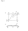
- the plate 19 has a substantially rectangular plate body 30 and projections or teeth 20 which are formed by bending the four corners of the plate body to a direction. The teeth are triangles as seen from the front that are long in the direction of the length of the plate body 30. Each of the tips 31 of the teeth 20 has an acute angle ⁇ of about 10 to 13 degrees.
- the length h of the shorter sides of the plate body 30 is smaller than the height H of the frame 17.
- the plate body 30 has a throughhole 21 at substantially its center.
- the throughhole 21 has a hexagonal shape which is substantially the same that the section of the engaging portion 14 has.
- the size of the hole 21 is in conformity with the size of the engaging portion 14 so that a rotation of the engaging portion 14 relative to the plate 19 is prevented by the hole 21.
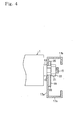
- the shafts 6, 7 of the motorized roller 1 are fastened to the side walls 17a via a plate 19 with the end face of the supporting portion 13 abutting to the inner surface, which is the left side in the figure, of the side wall 17a.
- the plate 19 is positioned with the teeth 20 projecting to the side wall 17a.
- the engaging portion 14 is fitted into the throughhole 21 of the plate 19 so as to prevent rotation of the shaft 6, 7 relative to the plate 19.
- a nut 22, functioning as a fastener, is mounted on the threaded portion 15 so as to press or urge the plate 19 against the side wall 17a of the frame 17.
- the plate 19 is formed by making athroughhole 21 at substantially the center of the plate body 30 and forming teeth 20 at the four corners of the plate body 30.
- a rotational force acting on the plate 19 about the axis of the shaft 6, 7 is distributed and transmitted to all the teeth 20 substantially evenly, dissipated into the frame 17 via tips 31 and relieved.
- rotation of the plate 19 relative to the frame 17 is firmly prevented.
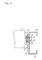
- shafts 6, 7 may be fastened through the plate 19 disposed inside of the side wall 17a (the left side in the figure), as shown in Fig. 5.
- the shaft 6 or 7 in this embodiment has a supporting portion 13 and an engaging portion 14.
- a threaded bore 27 for fastening a bolt 25, which functions as a fastener, is formed axially in each of the shafts 6, 7.
- a shaft or shank 26 of a bolt 25 is capable of being screwed axially into the bore 27 from the engaging portion side.
- the bolt 25 is fastened to the engaging portion 14 by being screwed from outside of the side wall 17a through the hole 18 into the threaded bore 27, thus the supporting portion 13 presses or urges the plate 19 against the side wall 17a.
- the engaging portion 14 of the shaft 6, 7 is fitted into the hole 21 of the plate 19, the shaft 6, 7 is unrotatable relative to the plate 19.
- the supporting portion 13 abuts to a surface of the plate 19.
- the surface is on the other side of the teeth 20.
- the teeth 20 of the plate 19 bite into the inner surface of the side wall 17a.
- the shank 26 of the bolt 25 extends through the hole 18 of the frame 17 from outside of theside wall 17a.
- the bolt head 28 of the bolt 25 abuts to the outer surface of the side wall 17a.
- the shaft 6, 7 is prevented from rotation relative to the plate 19, and the plate 19 is in turn not rotatable relative to the side wall 17a as the teeth 20 bite into the side wall 17a.
- the shaft 6, 7 is fastened unrotatably relative to the side wall 17a.
- the plate 19 is fastened to the frame 17, being incapable of relative rotation, dispensing with screws.
- the invention enables the fastening of the shafts 6, 7 to the frame 17 by only making a throughhole 18 at a predetermined position on the frame and makes the mounting of the shafts 6, 7 easier and faster.
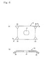
- the shape of the throughhole 21 of the plate 19 can be modified in conformity with the shape of the section of the shaft 6, 7, as shown in Fig. 6(a).
- the hole 21 has substantially the same shape and size that the section of the engaging portion 14 has, in order to prevent rotation of the shaft 6, 7 relative to the plate 19 more firmly.
- the throughhole 21 may have any shape if the shaft 6, 7 is prevented from rotation relative to the plate 19 when a rotational force acts on the shaft 6, 7.
- the plate 19 may have trapezoidal tabs 23 formed around the throughhole 21 by burring, as shown in Fig. 7(a), 7(b) and 7(c). If the shaft 6 or 7 is fitted in the throughhole 21 of the plate 19, a tapered washer 24 is mounted on the tabs 24, and the nut 22 is mounted on the shaft 6, 7, as shown in Fig. 8(a), the tapered washer 24 shifts toward the plate 19, pressing the tabs 23, which are deformed into shapes in conformity with the engaging portion of the shaft 6, 7, and prevents rotation of the shaft 6, 7 relative to the plate 19 without fault. As the tabs 23 are deformed into shapes in conformity with the engaging portion 14, rotation of the shaft 6, 7 relative to the plate 19 is prevented without fault, regardless of the shape of the shaft 6, 7.
- teeth 20 may be formed at any cite, e.g. on the periphery, of the plate 19, as shown in Fig.9(a) and 9(b).
- the plate 19 may be formed by bending the four corners of a substantially rectangular steel plate.
- the plate 19 may be formed by bending the four corners of a nealy rectangular steel plate that has four projections, which transform into the teeth, at the four comers.
- the plate may be made of suitable solid material. For example, it may be made by bending a plate made of metal such as aluminum and copper or by molding a plastic.
- the teeth 20 of the plate 19 in the above-mentioned embodiment have tips 31 with an angle ⁇ of 10 to 13 degrees
- the angle ⁇ of the tips is not limited in the range.
- the angle ⁇ is an acute angle. It is more preferably within the range from 5 to 60 degrees, further more preferably within the range from 5 to 30 degrees, and most preferably within the range from 10 to 13 degrees.
- the invention is not limited by the shaft 6, 7 including the three portions, namely, the supporting portion 13, the engaging portion 14, and the threaded portion 16.
- the shaft 6, 7 may be made by scraping down a threaded shaft to form two parallel flat faces, like the shaft 51 of the prior art motorized roller 50 shown in Fig. 10.
- the invention is not limited by the fact that the section of the engaging portion 14 of the shaft 6, 7 has the same shape as the throughhole 21 of the plate, either.
- the fastener mounted on the shaft 6, 7 is not limited to a nut 22 or a bolt 25 shown in the above-mentioned embodiments.
- a fastener such as a retaining ring or a snap ring can be used to prevent axial movement of the shaft 6, 7 and to press or urge the plate 19 against the frame 17.
- the invention is applicable to fastening of any shaft, not limited by the above-mentioned embodiments in which fastening of a shaft of a motorized roller or a free roller incorporating no driving source is illustrated.
- the invention enables fastening of the plate to the fixed body dispensing with screws and the like, that is, without making threaded bores and the like, so that fastening and mounting of shafts and rollers is performed easily and quickly regardless of shape of the fixed body.
- the shaft is not rotatable relative to the plate and the plate is fastened to the fixed body, the shaft is fastened to the fixed body so that it is unrotatable relatively to the body.
Landscapes
- Engineering & Computer Science (AREA)
- Mechanical Engineering (AREA)
- Rollers For Roller Conveyors For Transfer (AREA)
- Connection Of Plates (AREA)
- Standing Axle, Rod, Or Tube Structures Coupled By Welding, Adhesion, Or Deposition (AREA)
- Bolts, Nuts, And Washers (AREA)
- Rolls And Other Rotary Bodies (AREA)
Applications Claiming Priority (2)
| Application Number | Priority Date | Filing Date | Title |
|---|---|---|---|
| JP2001250757A JP2003056528A (ja) | 2001-08-21 | 2001-08-21 | 支軸の固定装置、並びに、ローラ装置の固定装置 |
| JP2001250757 | 2001-08-21 |
Publications (3)
| Publication Number | Publication Date |
|---|---|
| EP1285869A2 true EP1285869A2 (de) | 2003-02-26 |
| EP1285869A3 EP1285869A3 (de) | 2003-08-27 |
| EP1285869B1 EP1285869B1 (de) | 2007-06-27 |
Family
ID=19079514
Family Applications (1)
| Application Number | Title | Priority Date | Filing Date |
|---|---|---|---|
| EP02014695A Expired - Lifetime EP1285869B1 (de) | 2001-08-21 | 2002-07-03 | Befestigungsvorrichtung für Achsen und Konstruktion zur Befestigung von Rollen |
Country Status (5)
| Country | Link |
|---|---|
| US (1) | US6726003B2 (de) |
| EP (1) | EP1285869B1 (de) |
| JP (1) | JP2003056528A (de) |
| CN (1) | CN1199834C (de) |
| DE (1) | DE60220862T2 (de) |
Cited By (7)
| Publication number | Priority date | Publication date | Assignee | Title |
|---|---|---|---|---|
| FR2870528A3 (fr) * | 2004-05-18 | 2005-11-25 | David Sas Soc Par Actions Simp | Rouleaux de manutention incluant une cartouche motorisee |
| WO2006014258A1 (en) * | 2004-07-02 | 2006-02-09 | Dematic Corp. | Roller shaft mount |
| WO2013053499A1 (de) * | 2011-10-13 | 2013-04-18 | Interroll Holding Ag | Rollenförderer mit einer drehmomentenstütze |
| WO2015051391A1 (de) * | 2013-10-11 | 2015-04-16 | Tgw Mechanics Gmbh | Schwenklager und förderrolle für einen schrägen einbau derselben in eine förderanlage |
| US9511938B2 (en) | 2013-10-11 | 2016-12-06 | Tgw Mechanics Gmbh | Conveyor system having substantially symmetrical longitudinally running electric conductors |
| US9586763B2 (en) | 2013-10-11 | 2017-03-07 | Tgw Mechanics Gmbh | Conveyor roller and conveyor system with moisture protection |
| US9745141B2 (en) | 2013-11-06 | 2017-08-29 | Tgw Mechanics Gmbh | Method for addressing/sequencing linearly interlinked control components of a conveying system |
Families Citing this family (34)
| Publication number | Priority date | Publication date | Assignee | Title |
|---|---|---|---|---|
| US6918238B2 (en) * | 2003-07-21 | 2005-07-19 | Cnh America Llc | Preloadable, externally installable and removable bearing and shaft assembly |
| US20050087428A1 (en) * | 2003-10-28 | 2005-04-28 | Pelak Thomas J. | Flush mounted motorized roller for conveyor |
| US7228952B2 (en) * | 2004-08-11 | 2007-06-12 | Van Der Graaf Inc. | Conveyor roller shaft support for dampening vibrations |
| FR2879269B1 (fr) * | 2004-12-14 | 2008-04-25 | Valeo Thermique Moteur Sas | Dispositif de fixation d'un elememt sur un support |
| US7694843B2 (en) * | 2005-05-27 | 2010-04-13 | Prairie Packaging, Inc. | Reinforced plastic foam cup, method of and apparatus for manufacturing same |
| US20070036630A1 (en) * | 2005-08-12 | 2007-02-15 | 3Bz Ltd, A Limited Liability Company | Penetrating washer |
| DE102005046763A1 (de) * | 2005-09-29 | 2007-04-12 | Siemens Ag | Rollenantrieb und Rollentransporteinrichtung |
| US20070261933A1 (en) * | 2006-04-26 | 2007-11-15 | Scott C W | Conveyor roller assembly and conveyor roller insert |
| US7842626B2 (en) * | 2006-11-13 | 2010-11-30 | E. I. Du Pont De Nemours And Company | Partially fluorinated compositions and surface active agents |
| US20090045029A1 (en) * | 2007-08-16 | 2009-02-19 | Deur Delwyn G | Conveyor roller and cartridge bearing assembly for same |
| JP2009287619A (ja) * | 2008-05-28 | 2009-12-10 | Parts Seiko:Kk | 高さ調整装置および高さ調整装置のねじ軸の製造方法 |
| US7588135B1 (en) * | 2008-06-23 | 2009-09-15 | Worldwide Logistics Corporation | Roller mount for a roller of a conveyer |
| JP2010013220A (ja) * | 2008-07-02 | 2010-01-21 | Tomei Kosan Kk | 搬送装置 |
| JP5224598B2 (ja) * | 2009-03-31 | 2013-07-03 | 伊東電機株式会社 | コンベア装置及びモータ内蔵ローラ取り付け器具 |
| AT508861A1 (de) * | 2009-09-18 | 2011-04-15 | Tgw Mechanics Gmbh | Rollenförderer und verfahren zum betreiben desselben |
| CN102076201A (zh) * | 2009-11-20 | 2011-05-25 | 鸿富锦精密工业(深圳)有限公司 | 托架 |
| CN102022424A (zh) * | 2010-11-10 | 2011-04-20 | 无锡真木物流设备有限公司 | 无动力滚筒结构 |
| JP5674599B2 (ja) * | 2011-08-31 | 2015-02-25 | 株式会社ブリヂストン | 管継手 |
| CN102556619A (zh) * | 2012-01-18 | 2012-07-11 | 浙江师范大学 | 输送机托辊连接结构 |
| CN102658222A (zh) * | 2012-05-14 | 2012-09-12 | 李清 | 多级破碎制砂机 |
| CN102700902A (zh) * | 2012-06-29 | 2012-10-03 | 中国铁建重工集团有限公司 | 一种皮带输送机的驱动装置 |
| CN102991986A (zh) * | 2012-12-10 | 2013-03-27 | 中山市盈科轴承制造有限公司 | 一种与输送平台上的输送托辊相配合的支承组件 |
| JP5759972B2 (ja) * | 2012-12-25 | 2015-08-05 | 京セラドキュメントソリューションズ株式会社 | 取付補助部材およびこれを備えた光走査装置 |
| CN103148072B (zh) * | 2013-03-11 | 2015-12-09 | 苏州市奥杰汽车技术有限公司 | 一种方管铝型材的连接结构 |
| US10308442B2 (en) * | 2014-02-28 | 2019-06-04 | Itoh Denki Co., Ltd. | Conveyed-object discharge device |
| JP6715455B2 (ja) * | 2014-07-07 | 2020-07-01 | 株式会社NejiLaw | ねじ体締結構造 |
| CN105836412A (zh) * | 2016-03-25 | 2016-08-10 | 李理 | 一种导向滚筒安装架 |
| CN105936404A (zh) * | 2016-05-18 | 2016-09-14 | 浙江海洋大学 | 石油加工用内驱动式输送带 |
| US20160280468A1 (en) * | 2016-06-08 | 2016-09-29 | Caterpillar Paving Products Inc. | Conveyor system for cold planer |
| US9637319B1 (en) * | 2016-09-02 | 2017-05-02 | Amazon Technologies, Inc. | Tote handling systems and methods |
| US10583992B2 (en) * | 2018-02-23 | 2020-03-10 | Frantz Manufacturing Company | Stub axles conveyor rollers |
| CN111188817B (zh) * | 2020-01-08 | 2021-11-05 | 江苏启微半导体设备有限公司 | 一种湿法处理设备机械手臂安装骨架及其安装方法 |
| DE102020133619B8 (de) | 2020-12-15 | 2023-07-06 | Interroll Holding Ag | Rollenförderer |
| US11639268B2 (en) * | 2021-06-23 | 2023-05-02 | Intelligrated Headquarters, Llc | Axle lock assembly for motor driven rollers |
Citations (2)
| Publication number | Priority date | Publication date | Assignee | Title |
|---|---|---|---|---|
| JPH06312832A (ja) | 1993-04-28 | 1994-11-08 | Ito Denki Kk | クロスフィーダ |
| JPH11268815A (ja) | 1998-03-20 | 1999-10-05 | Ito Denki Kk | ローラの取り付け構造及びローラの軸固定具 |
Family Cites Families (14)
| Publication number | Priority date | Publication date | Assignee | Title |
|---|---|---|---|---|
| US464301A (en) * | 1891-12-01 | Resilient spiral washer and maksng of the same | ||
| US2304155A (en) * | 1941-04-10 | 1942-12-08 | Dyball Ernest George | Joint washer |
| US3610659A (en) * | 1969-06-04 | 1971-10-05 | Donald R Gerarde | Wheel fork |
| US4078641A (en) * | 1974-04-04 | 1978-03-14 | F.E.I., Inc. | Sanitary roller conveyor |
| JPS5267450A (en) * | 1975-10-28 | 1977-06-03 | Kinoshita Seiki Kk | Plate spring washer |
| US4213523A (en) * | 1978-09-11 | 1980-07-22 | C. L. Frost & Son, Inc. | Conveyor roller assembly |
| US4681215A (en) * | 1985-02-28 | 1987-07-21 | Rexnord Inc. | Conveyor roller and bearing assembly with external support |
| US5088596A (en) * | 1990-12-17 | 1992-02-18 | Interroll Holding A. G. | Motorized conveyor roller |
| CA2122631A1 (en) * | 1991-11-01 | 1993-05-13 | Norman Leslie Matthews | Fastener bearing assembly |
| US5421441A (en) * | 1994-02-22 | 1995-06-06 | Mason; William R. | Stub axle assembly for conveyor roller |
| US6244427B1 (en) * | 1997-09-16 | 2001-06-12 | Motion Systems, L.C. | Modular gearless motorized conveyor roller |
| US6076647A (en) * | 1997-09-29 | 2000-06-20 | Interroll Holding Ag | Stub shaft conveyor roller |
| US6131717A (en) * | 1998-06-05 | 2000-10-17 | Pemco Engineers | Braking roller |
| US5967721A (en) * | 1998-09-18 | 1999-10-19 | Allen-Bradley Company, Llc | Loosening-resistant threaded fastener system and method of use |
-
2001
- 2001-08-21 JP JP2001250757A patent/JP2003056528A/ja active Pending
-
2002
- 2002-07-03 EP EP02014695A patent/EP1285869B1/de not_active Expired - Lifetime
- 2002-07-03 DE DE60220862T patent/DE60220862T2/de not_active Expired - Lifetime
- 2002-07-31 CN CNB021272999A patent/CN1199834C/zh not_active Expired - Lifetime
- 2002-08-12 US US10/217,078 patent/US6726003B2/en not_active Expired - Fee Related
Patent Citations (2)
| Publication number | Priority date | Publication date | Assignee | Title |
|---|---|---|---|---|
| JPH06312832A (ja) | 1993-04-28 | 1994-11-08 | Ito Denki Kk | クロスフィーダ |
| JPH11268815A (ja) | 1998-03-20 | 1999-10-05 | Ito Denki Kk | ローラの取り付け構造及びローラの軸固定具 |
Cited By (11)
| Publication number | Priority date | Publication date | Assignee | Title |
|---|---|---|---|---|
| FR2870528A3 (fr) * | 2004-05-18 | 2005-11-25 | David Sas Soc Par Actions Simp | Rouleaux de manutention incluant une cartouche motorisee |
| WO2006014258A1 (en) * | 2004-07-02 | 2006-02-09 | Dematic Corp. | Roller shaft mount |
| WO2013053499A1 (de) * | 2011-10-13 | 2013-04-18 | Interroll Holding Ag | Rollenförderer mit einer drehmomentenstütze |
| US9150357B2 (en) | 2011-10-13 | 2015-10-06 | Interroll Holding Ag | Roller conveyor with torque support |
| WO2015051391A1 (de) * | 2013-10-11 | 2015-04-16 | Tgw Mechanics Gmbh | Schwenklager und förderrolle für einen schrägen einbau derselben in eine förderanlage |
| CN105764818A (zh) * | 2013-10-11 | 2016-07-13 | Tgw机械有限公司 | 枢转支承件和用于倾斜地安装到输送设备中的输送辊 |
| US9511938B2 (en) | 2013-10-11 | 2016-12-06 | Tgw Mechanics Gmbh | Conveyor system having substantially symmetrical longitudinally running electric conductors |
| US9586763B2 (en) | 2013-10-11 | 2017-03-07 | Tgw Mechanics Gmbh | Conveyor roller and conveyor system with moisture protection |
| US9776806B2 (en) | 2013-10-11 | 2017-10-03 | Tgw Mechanics Gmbh | Pivot bearing and conveying roller for an oblique mounting of the same in a conveyor system |
| CN105764818B (zh) * | 2013-10-11 | 2019-02-01 | Tgw机械有限公司 | 枢转支承件和用于倾斜地安装到输送设备中的输送辊 |
| US9745141B2 (en) | 2013-11-06 | 2017-08-29 | Tgw Mechanics Gmbh | Method for addressing/sequencing linearly interlinked control components of a conveying system |
Also Published As
| Publication number | Publication date |
|---|---|
| DE60220862D1 (de) | 2007-08-09 |
| US20030038014A1 (en) | 2003-02-27 |
| EP1285869B1 (de) | 2007-06-27 |
| JP2003056528A (ja) | 2003-02-26 |
| CN1406841A (zh) | 2003-04-02 |
| DE60220862T2 (de) | 2008-02-28 |
| US6726003B2 (en) | 2004-04-27 |
| CN1199834C (zh) | 2005-05-04 |
| EP1285869A3 (de) | 2003-08-27 |
Similar Documents
| Publication | Publication Date | Title |
|---|---|---|
| US6726003B2 (en) | Fastening structure and mounting structure | |
| KR100498866B1 (ko) | 고정장치 | |
| KR100559944B1 (ko) | 대상물을 조이고 푸는 방법 | |
| JP2992937B2 (ja) | ナット及び同ナットを用いる締付装置 | |
| US7721627B2 (en) | Attachments for power tools | |
| EP1094232B1 (de) | Bolzen und Befestigungsanordnung | |
| EP0600854A1 (de) | Anziehbare Mutter | |
| TW409090B (en) | Power tool | |
| US7905162B2 (en) | Low profile wrench | |
| EP0643230A1 (de) | Mutter oder Bolzen mit Feineinstellung | |
| US4813308A (en) | Tool adapter and method of using same | |
| US7827885B2 (en) | Drive extension wrench | |
| JPS61228157A (ja) | スクリユ−ナツト駆動装置 | |
| US8689842B2 (en) | Tire insert attachment apparatus | |
| US4391431A (en) | Device for tightening coarse thread connections | |
| KR20040063758A (ko) | 너트, 너트가 구비된 고정구와, 이를 위한 고정장치 | |
| US5001947A (en) | Dual operation ratchet wrench | |
| GB2160137A (en) | A tool | |
| US20070107558A1 (en) | Power tool | |
| US20040103761A1 (en) | Fixed angle extension for a tool | |
| JPS60161051A (ja) | ボ−ルねじを使用した加工機械の送り装置 | |
| US20240109168A1 (en) | Socket driver assembly for tight spaces | |
| JP2003301829A (ja) | ボルト・ナットの緩み止め構造 | |
| KR0132927B1 (ko) | 렌치 지그 | |
| JP2001330020A (ja) | ねじ用取外し防止材 |
Legal Events
| Date | Code | Title | Description |
|---|---|---|---|
| PUAI | Public reference made under article 153(3) epc to a published international application that has entered the european phase |
Free format text: ORIGINAL CODE: 0009012 |
|
| AK | Designated contracting states |
Kind code of ref document: A2 Designated state(s): AT BE BG CH CY CZ DE DK EE ES FI FR GB GR IE IT LI LU MC NL PT SE SK TR Designated state(s): AT BE BG CH CY CZ DE DK EE ES FI FR GB GR IE IT LI LU MC NL PT SE SK TR |
|
| AX | Request for extension of the european patent |
Extension state: AL LT LV MK RO SI |
|
| PUAL | Search report despatched |
Free format text: ORIGINAL CODE: 0009013 |
|
| AK | Designated contracting states |
Designated state(s): AT BE BG CH CY CZ DE DK EE ES FI FR GB GR IE IT LI LU MC NL PT SE SK TR |
|
| AX | Request for extension of the european patent |
Extension state: AL LT LV MK RO SI |
|
| AKX | Designation fees paid | ||
| 17P | Request for examination filed |
Effective date: 20030920 |
|
| RBV | Designated contracting states (corrected) |
Designated state(s): DE FR GB |
|
| REG | Reference to a national code |
Ref country code: DE Ref legal event code: 8566 |
|
| 17Q | First examination report despatched |
Effective date: 20040615 |
|
| GRAP | Despatch of communication of intention to grant a patent |
Free format text: ORIGINAL CODE: EPIDOSNIGR1 |
|
| GRAS | Grant fee paid |
Free format text: ORIGINAL CODE: EPIDOSNIGR3 |
|
| GRAA | (expected) grant |
Free format text: ORIGINAL CODE: 0009210 |
|
| AK | Designated contracting states |
Kind code of ref document: B1 Designated state(s): DE FR GB |
|
| REG | Reference to a national code |
Ref country code: GB Ref legal event code: FG4D |
|
| REF | Corresponds to: |
Ref document number: 60220862 Country of ref document: DE Date of ref document: 20070809 Kind code of ref document: P |
|
| ET | Fr: translation filed | ||
| PLBE | No opposition filed within time limit |
Free format text: ORIGINAL CODE: 0009261 |
|
| STAA | Information on the status of an ep patent application or granted ep patent |
Free format text: STATUS: NO OPPOSITION FILED WITHIN TIME LIMIT |
|
| 26N | No opposition filed |
Effective date: 20080328 |
|
| REG | Reference to a national code |
Ref country code: FR Ref legal event code: PLFP Year of fee payment: 15 |
|
| REG | Reference to a national code |
Ref country code: FR Ref legal event code: PLFP Year of fee payment: 16 |
|
| REG | Reference to a national code |
Ref country code: FR Ref legal event code: PLFP Year of fee payment: 17 |
|
| PGFP | Annual fee paid to national office [announced via postgrant information from national office to epo] |
Ref country code: GB Payment date: 20210629 Year of fee payment: 20 |
|
| PGFP | Annual fee paid to national office [announced via postgrant information from national office to epo] |
Ref country code: FR Payment date: 20210702 Year of fee payment: 20 |
|
| PGFP | Annual fee paid to national office [announced via postgrant information from national office to epo] |
Ref country code: DE Payment date: 20210629 Year of fee payment: 20 |
|
| REG | Reference to a national code |
Ref country code: DE Ref legal event code: R071 Ref document number: 60220862 Country of ref document: DE |
|
| REG | Reference to a national code |
Ref country code: GB Ref legal event code: PE20 Expiry date: 20220702 |
|
| PG25 | Lapsed in a contracting state [announced via postgrant information from national office to epo] |
Ref country code: GB Free format text: LAPSE BECAUSE OF EXPIRATION OF PROTECTION Effective date: 20220702 |