EP1285718B9 - Werkzeugmaschine zum Bearbeiten von Werkstücken mittels eines Laserstrahls - Google Patents
Werkzeugmaschine zum Bearbeiten von Werkstücken mittels eines Laserstrahls Download PDFInfo
- Publication number
- EP1285718B9 EP1285718B9 EP01119997A EP01119997A EP1285718B9 EP 1285718 B9 EP1285718 B9 EP 1285718B9 EP 01119997 A EP01119997 A EP 01119997A EP 01119997 A EP01119997 A EP 01119997A EP 1285718 B9 EP1285718 B9 EP 1285718B9
- Authority
- EP
- European Patent Office
- Prior art keywords
- laser
- axis
- trombone
- guide structure
- movement
- Prior art date
- Legal status (The legal status is an assumption and is not a legal conclusion. Google has not performed a legal analysis and makes no representation as to the accuracy of the status listed.)
- Expired - Lifetime
Links
- 238000003754 machining Methods 0.000 title abstract description 7
- 238000003698 laser cutting Methods 0.000 abstract description 25
- 230000003044 adaptive effect Effects 0.000 abstract 1
- 101100390736 Danio rerio fign gene Proteins 0.000 description 2
- 101100390738 Mus musculus Fign gene Proteins 0.000 description 2
- 238000000034 method Methods 0.000 description 2
- 230000001419 dependent effect Effects 0.000 description 1
- 238000005516 engineering process Methods 0.000 description 1
- 230000004886 head movement Effects 0.000 description 1
- 230000000284 resting effect Effects 0.000 description 1
- 239000006228 supernatant Substances 0.000 description 1
Images


Classifications
-
- B—PERFORMING OPERATIONS; TRANSPORTING
- B23—MACHINE TOOLS; METAL-WORKING NOT OTHERWISE PROVIDED FOR
- B23K—SOLDERING OR UNSOLDERING; WELDING; CLADDING OR PLATING BY SOLDERING OR WELDING; CUTTING BY APPLYING HEAT LOCALLY, e.g. FLAME CUTTING; WORKING BY LASER BEAM
- B23K26/00—Working by laser beam, e.g. welding, cutting or boring
- B23K26/08—Devices involving relative movement between laser beam and workpiece
- B23K26/0869—Devices involving movement of the laser head in at least one axial direction
- B23K26/0876—Devices involving movement of the laser head in at least one axial direction in at least two axial directions
-
- B—PERFORMING OPERATIONS; TRANSPORTING
- B23—MACHINE TOOLS; METAL-WORKING NOT OTHERWISE PROVIDED FOR
- B23K—SOLDERING OR UNSOLDERING; WELDING; CLADDING OR PLATING BY SOLDERING OR WELDING; CUTTING BY APPLYING HEAT LOCALLY, e.g. FLAME CUTTING; WORKING BY LASER BEAM
- B23K26/00—Working by laser beam, e.g. welding, cutting or boring
- B23K26/02—Positioning or observing the workpiece, e.g. with respect to the point of impact; Aligning, aiming or focusing the laser beam
- B23K26/06—Shaping the laser beam, e.g. by masks or multi-focusing
-
- B—PERFORMING OPERATIONS; TRANSPORTING
- B23—MACHINE TOOLS; METAL-WORKING NOT OTHERWISE PROVIDED FOR
- B23K—SOLDERING OR UNSOLDERING; WELDING; CLADDING OR PLATING BY SOLDERING OR WELDING; CUTTING BY APPLYING HEAT LOCALLY, e.g. FLAME CUTTING; WORKING BY LASER BEAM
- B23K26/00—Working by laser beam, e.g. welding, cutting or boring
- B23K26/08—Devices involving relative movement between laser beam and workpiece
- B23K26/0869—Devices involving movement of the laser head in at least one axial direction
-
- B—PERFORMING OPERATIONS; TRANSPORTING
- B23—MACHINE TOOLS; METAL-WORKING NOT OTHERWISE PROVIDED FOR
- B23K—SOLDERING OR UNSOLDERING; WELDING; CLADDING OR PLATING BY SOLDERING OR WELDING; CUTTING BY APPLYING HEAT LOCALLY, e.g. FLAME CUTTING; WORKING BY LASER BEAM
- B23K26/00—Working by laser beam, e.g. welding, cutting or boring
- B23K26/08—Devices involving relative movement between laser beam and workpiece
- B23K26/0869—Devices involving movement of the laser head in at least one axial direction
- B23K26/0892—Controlling the laser beam travel length
-
- B—PERFORMING OPERATIONS; TRANSPORTING
- B23—MACHINE TOOLS; METAL-WORKING NOT OTHERWISE PROVIDED FOR
- B23K—SOLDERING OR UNSOLDERING; WELDING; CLADDING OR PLATING BY SOLDERING OR WELDING; CUTTING BY APPLYING HEAT LOCALLY, e.g. FLAME CUTTING; WORKING BY LASER BEAM
- B23K37/00—Auxiliary devices or processes, not specially adapted for a procedure covered by only one of the other main groups of this subclass
- B23K37/02—Carriages for supporting the welding or cutting element
- B23K37/0211—Carriages for supporting the welding or cutting element travelling on a guide member, e.g. rail, track
- B23K37/0229—Carriages for supporting the welding or cutting element travelling on a guide member, e.g. rail, track the guide member being situated alongside the workpiece
-
- B—PERFORMING OPERATIONS; TRANSPORTING
- B23—MACHINE TOOLS; METAL-WORKING NOT OTHERWISE PROVIDED FOR
- B23Q—DETAILS, COMPONENTS, OR ACCESSORIES FOR MACHINE TOOLS, e.g. ARRANGEMENTS FOR COPYING OR CONTROLLING; MACHINE TOOLS IN GENERAL CHARACTERISED BY THE CONSTRUCTION OF PARTICULAR DETAILS OR COMPONENTS; COMBINATIONS OR ASSOCIATIONS OF METAL-WORKING MACHINES, NOT DIRECTED TO A PARTICULAR RESULT
- B23Q1/00—Members which are comprised in the general build-up of a form of machine, particularly relatively large fixed members
- B23Q1/01—Frames, beds, pillars or like members; Arrangement of ways
- B23Q1/012—Portals
-
- B—PERFORMING OPERATIONS; TRANSPORTING
- B23—MACHINE TOOLS; METAL-WORKING NOT OTHERWISE PROVIDED FOR
- B23Q—DETAILS, COMPONENTS, OR ACCESSORIES FOR MACHINE TOOLS, e.g. ARRANGEMENTS FOR COPYING OR CONTROLLING; MACHINE TOOLS IN GENERAL CHARACTERISED BY THE CONSTRUCTION OF PARTICULAR DETAILS OR COMPONENTS; COMBINATIONS OR ASSOCIATIONS OF METAL-WORKING MACHINES, NOT DIRECTED TO A PARTICULAR RESULT
- B23Q1/00—Members which are comprised in the general build-up of a form of machine, particularly relatively large fixed members
- B23Q1/01—Frames, beds, pillars or like members; Arrangement of ways
- B23Q1/017—Arrangements of ways
-
- B—PERFORMING OPERATIONS; TRANSPORTING
- B23—MACHINE TOOLS; METAL-WORKING NOT OTHERWISE PROVIDED FOR
- B23Q—DETAILS, COMPONENTS, OR ACCESSORIES FOR MACHINE TOOLS, e.g. ARRANGEMENTS FOR COPYING OR CONTROLLING; MACHINE TOOLS IN GENERAL CHARACTERISED BY THE CONSTRUCTION OF PARTICULAR DETAILS OR COMPONENTS; COMBINATIONS OR ASSOCIATIONS OF METAL-WORKING MACHINES, NOT DIRECTED TO A PARTICULAR RESULT
- B23Q1/00—Members which are comprised in the general build-up of a form of machine, particularly relatively large fixed members
- B23Q1/25—Movable or adjustable work or tool supports
- B23Q1/44—Movable or adjustable work or tool supports using particular mechanisms
- B23Q1/56—Movable or adjustable work or tool supports using particular mechanisms with sliding pairs only, the sliding pairs being the first two elements of the mechanism
- B23Q1/60—Movable or adjustable work or tool supports using particular mechanisms with sliding pairs only, the sliding pairs being the first two elements of the mechanism two sliding pairs only, the sliding pairs being the first two elements of the mechanism
- B23Q1/601—Movable or adjustable work or tool supports using particular mechanisms with sliding pairs only, the sliding pairs being the first two elements of the mechanism two sliding pairs only, the sliding pairs being the first two elements of the mechanism a single sliding pair followed parallelly by a single sliding pair
-
- B—PERFORMING OPERATIONS; TRANSPORTING
- B23—MACHINE TOOLS; METAL-WORKING NOT OTHERWISE PROVIDED FOR
- B23Q—DETAILS, COMPONENTS, OR ACCESSORIES FOR MACHINE TOOLS, e.g. ARRANGEMENTS FOR COPYING OR CONTROLLING; MACHINE TOOLS IN GENERAL CHARACTERISED BY THE CONSTRUCTION OF PARTICULAR DETAILS OR COMPONENTS; COMBINATIONS OR ASSOCIATIONS OF METAL-WORKING MACHINES, NOT DIRECTED TO A PARTICULAR RESULT
- B23Q5/00—Driving or feeding mechanisms; Control arrangements therefor
- B23Q5/22—Feeding members carrying tools or work
- B23Q5/34—Feeding other members supporting tools or work, e.g. saddles, tool-slides, through mechanical transmission
- B23Q5/38—Feeding other members supporting tools or work, e.g. saddles, tool-slides, through mechanical transmission feeding continuously
- B23Q5/385—Feeding other members supporting tools or work, e.g. saddles, tool-slides, through mechanical transmission feeding continuously using a gear and rack mechanism or a friction wheel co-operating with a rail
Definitions
- Such a machine tool is known from JP 08 052587 A.
- a machine tool is known from JP 08 052587 A.
- the boom can be moved along the machine bed and in turn transverses a laser processing head to the machine bed.
- a beam guide of the previously known machine leads a laser beam from a laser generator to the Laser processing head.
- the beam guide includes i.a. a Beam trombone, by means of which the laser beam length between the Regardless of the laser generator and the laser processing head Movements is held constant, which during workpiece machining from the laser processing head along the cantilever and / or carried out by the boom along the machine bed become.
- a beam deflection of the beam trombone moves also in the longitudinal direction of the machine bed.
- the laser processing head has the Beam deflection of the beam trombone attached to the machine bed Underride part of the boom.
- the laser generator is raised so far from the machine bed, that he can be driven under by the boom.
- Corresponding large is the total height of the known machine.
- the beam deflection of the machine according to EP 0 559 916 A1 is the Working area of the laser processing head in the transverse direction of the the laser processing head leading bridge adjacent and movable in the bridge longitudinal direction.
- the laser beam source is in the longitudinal direction of the bridge against the working area of the Laser processing head offset.
- Claim 4 describes a functionally reliable and manufactur- as well as montertechnisch easy to implement possibility for the common use of a drive rod by the drives the beam deflection of the beam trombone and the second management structure.
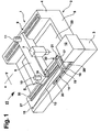
- the 1 has a laser processing machine, present a laser cutting machine 1, a machine frame 2, on which Machine longitudinal beams 3, 4 and between these a workpiece support 5 are formed.
- a bridge 6 On the machine side rails 3, 4 is a bridge 6 in the direction of a first axis of movement (x-axis) movable.
- the bridge 6 stores and leads a laser processing head in the form of a laser cutting head 7 in the direction of a second movement axis (y-axis).
- the machine longitudinal beams 3, 4 form a first guiding structure, the bridge 6 a second management structure.
- drives 8, 9 with electric drive motors 10, 11 cause the movement of the Bridge 6 with the laser cutting head 7 held in the direction the x-axis; a simplicity not shown Electric drive of conventional design provides the drive of the laser cutting head 7 in the direction of the y-axis.
- a laser beam source in the form of a CO 2 laser 12 rests on one of the two ends of the machine longitudinal carrier 3.
- the CO 2 laser 12 is used to generate a laser beam 13, which by means of a beam guide 14 from the CO 2 laser 12 to the laser cutting head. 7 is steered.
- the beam guide 14 includes deflection mirrors 15, 16, 17, 18, wherein the deflection mirrors 16, 17 are components of a beam deflection 19 of a beam trombone 20.
- the beam deflection 19 of the beam trombone 20 is on the machine longitudinal beam 3 in the direction of the x-axis and is by means of a drive 21 via a drive motor 22 moves.
- the beam trombone 20 serves to keep the length of the laser beam 13, ie the length of the propagation path of the laser beam 13 from the CO 2 laser 12 to the laser cutting head 7, in detail of the focusing lens provided there, constant.
- the beam deflection 19 is tuned to the movement which the laser cutting head 7 carries out during workpiece machining, for example when cutting a sheet 23 resting on the workpiece support 5. Moves the laser cutting head 7 approximately in Fig. 1 by a certain amount in the direction of the y-axis to the longitudinal Maschihenberichträger 4, so moves the beam deflection 19 at the same time on the machine longitudinal beam 3 along in the direction of the bridge 6.
- the CO 2 laser 2 is arranged elevated relative to the beam deflection 19 of the beam trombone 20. Consequently, the beam deflection 19 can drive the CO 2 laser 12 down as it travels to compensate for the movement of the laser cutting head 7.
- the deflection mirror 15 of the beam guide 14 serves as a beam guiding element for deflecting the laser beam 13 emitted by the CO 2 laser 12 to the beam deflection 19.
- the beam deflection 19 is in one of its movement end positions shown in the direction of the x-axis.
- the bridge 6 takes one of its movement end positions in the direction of the x-axis one.
- the laser cutting head 7 In the direction of the y-axis is the laser cutting head 7 in his lying to the machine longitudinal member 3 end position method.
- the laser cutting head 7 in FIG. 2 In its end position on the opposite End of the bridge 6 is the laser cutting head 7 in FIG. 2 shown in dashed lines.
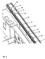
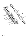
- the drive pinion 24, 25 are driven by the electric drive motors 10, 22 and mesh with a common rack 26, which with .dem machine longitudinal member 3 is screwed and there in the direction the x-axis runs.
- the guide rail 27 serves as a common guide rail for the bridge 6 and the beam deflection 19, the guide rail 28 for sole Guide the beam deflection 19.
- To control the drive 21 for the beam deflection 19 of the beam trombone 20 is as well as to control the drives 8, 9 for the bridge 6 and the control of the drive for the laser cutting head 7 a not shown CNC control provided. By means of this leaves the drive 21 of the beam deflection 19 matched to the Control of the drives 8, 9 of the bridge 6 and tuned to control the drive of the laser cutting head 7.
Landscapes
- Physics & Mathematics (AREA)
- Optics & Photonics (AREA)
- Engineering & Computer Science (AREA)
- Mechanical Engineering (AREA)
- Plasma & Fusion (AREA)
- Laser Beam Processing (AREA)
- Lasers (AREA)
- Electrical Discharge Machining, Electrochemical Machining, And Combined Machining (AREA)
Description
- wobei der Laserbearbeitungskopf bei der Werkstückbearbeitung relativ zu der Laserstrahlquelle bewegbar ist, indem die zweite Führungsstruktur mit dem Laserbearbeitungskopf an der ersten Führungsstruktur in Richtung einer ersten Bewegungsachse (x-Achse) bewegbar geführt ist und indem die zweite Führungsstruktur ihrerseits den Laserbearbeitungskopf in Richtung einer zweiten Bewegungsachse (y-Achse) bewegbar führt, die unter einem Winkel zu der ersten Bewegungsachse (x-Achse) verläuft,
- wobei die Strahlführung eine Strahlposaune mit einer Strahlumlenkung aufweist, wobei die Laserstrahlquelle gegenüber der Strahlumlenkung der Strahlposaune erhöht angeordnet ist, wobei die Strahlumlenkung bei der Bewegung des Laserbearbeitungskopfes relativ zu der Laserstrahlquelle auf diese Bewegung abgestimmt bewegbar an der ersten Führungsstruktur in Richtung der ersten Bewegungsachse (x-Achse) geführt ist und wobei die Strahlführung außerdem wenigstens ein Strahlführungselement aufweist, das in dem Weg des Laserstrahls zwischen der Laserstrahlquelle und der Strahlumlenkung der Strahlposaune vorgesehen und mittels dessen der von der Laserstrahlquelle ausgesandte Laserstrahl zu der Strahlumlenkung der Strahlposaune umlenkbar ist und
- wobei die zweite Führungsstruktur in Richtung der ersten Bewegungsachse (x-Achse) zu der Laserstrahlquelle hin in eine Bewegungs-Endstellung bewegbar ist und die Strahlumlenkung der Strahlposaune bei in der genannten Bewegungs-Endstellung befindlicher zweiter Führungsstruktur unter die Laserstrahlquelle bewegt ist.
- Fig. 1
- eine Laserbearbeitungsmaschine einschließlich Laserstrahlquelle, Strahlposaune mit Strahlumlenkung und Brücke mit Laserbearbeitungskopf in stark schematisierter Darstellung,
- Fig. 2
- die Laserbearbeitungsmaschine nach Fig. 1 (weniger stark schematisiert) in der Ansicht in Richtung des Pfeils II in Fig. 1,
- Fig. 3
- Antriebs- und Führungseinrichtungen für die Strahlumlenkung der Strahlposäune und für die Brücke nach den Fign. 1 und 2,
- Fig. 4
- die für die Strahlumlenkung der Strahlposaune vorgesehenen Antriebs- und Führungseinrichtungen nach Fig. 3 in vergrößerter Darstellung und
- Fig. 5
- die für die Brücke vorgesehenen Antriebs- und Führungseinrichtungen nach Fig. 3 in vergrößerter Darstellung.
Claims (5)
- Werkzeugmaschine zum Bearbeiten von Werkstücken mittels eines Laserstrahls (13), umfassend eine Laserstrahlquelle (12), einen Laserbearbeitungskopf (7), eine Strahlführung (14) zur Führung des Laserstrahls (13) von der Laserstrahlquelle (12) zu dem Laserbearbeitungskopf (7) sowie eine erste Führungsstruktur (3, 4) und eine zweite Führungsstruktur (6),dadurch gekennzeichnet, dasswobei der Laserbearbeitungskopf (7) bei der Werkstückbearbeitung relativ zu der Laserstrahlquelle (12) bewegbar ist, indem die zweite Führungsstruktur (6) mit dem Laserbearbeitungskopf (7) an der ersten Führungsstruktur (3, 4) in Richtung einer ersten Bewegungsachse (x-Achse) bewegbar geführt ist und indem die zweite Führungsstruktur (6) ihrerseits den Laserbearbeitungskopf (7) in Richtung einer zweiten Bewegungsachse (y-Achse) bewegbar führt, die unter einem Winkel zu der ersten Bewegungsachse (x-Achse) verläuft,wobei die Strahlführung (14) eine Strahlposaune (20) mit einer Strahlumlenkung (19) aufweist, wobei die Laserstrahlquelle (12), gegenüber der Strahlumlenkung (19) der Strahlposaune (20) erhöht angeordnet ist, wobei die Strahlumlenkung (19) bei der Bewegung des Laserbearbeitungskopfes (7) relativ zu der Laserstrahlquelle (12) auf diese Bewegung abgestimmt bewegbar an der ersten Führungsstruktur (3, 4) in Richtung der ersten Bewegungsachse (x-Achse) geführt ist und wobei die Strahlführung (14) außerdem wenigstens ein Strahlführungselement (15) aufweist, das in dem Weg des Laserstrahls (13) zwischen der Laserstrahlquelle (12) und der Strahlumlenkung (19) der Strahlposaune (20) vorgesehen und mittels dessen der von der Laserstrahlquelle (12) ausgesandte Laserstrahl (13) zu der Strahlumlenkung (19) der Strahlposaune (20) umlenkbar ist undwobei die zweite Führungsstruktur (6) in Richtung der ersten Bewegungsachse (x-Achse) zu der Laserstrahlquelle (12) hin in eine Bewegungs-Endstellung bewegbar ist und die Strahlumlenkung (19) der Strahlposaune (20) bei in der genannten Bewegungs-Endstellung befindlicher zweiter Führungsstruktur (6) unter die Laserstrahlquelle (12) bewegt ist,
die Strahlumlenkung (19) der Strahlposaune (20) bei der Bewegung des Laserbearbeitungskopfes (7) relativ zu der Laserstrahlquelle (12) in Richtung der ersten Bewegungsachse (x-Achse) gesehen stets an der zu der Laserstrahlquelle (12) hin liegenden Seite der zweiten Führungsstruktur (6) angeordnet ist. - Werkzeugmaschine nach Anspruch 1, dadurch gekennzeichne t, dass die erste Führungsstruktur (3, 4) gegenüber der ihre zu der Laserstrahlquelle (12) hin gelegene Bewegungs-Endstellung einnehmenden zweiten Führungsstruktur (6) an der der Strahlumlenkung (19) der Strahlposaune (20) zugewandten Seite der zweiten Führungsstruktur (6) einen Überstand aufweist, dessen Länge in Richtung der ersten Bewegungsachse (x-Achse) im Wesentlichen der betreffenden Abmessung der Strahlumlenkung (19) der Strahlposaune (20) zuzüglich der Länge desjenigen Weges entspricht, über welchen die Strahlumlenkung (19) der Strahlposaune (20) bei Bewegung des Laserbearbeitungskopfes (7) in Richtung der zweiten Bewegungsachse (y-Achse) maximal bewegbar ist.
- Werkzeugmaschine nach einem der vorhergehenden Ansprüche, dadurch gekennzeichnet, dass die Strahlumlenkung (19) der Strahlposaune (20) und die zweite Führungsstruktur (6) mittels jeweils wenigstens eines Antriebes (8, 9, 21) mit wenigstens einem mit der Strahlumlenkung (19) der Strahlposaune (20) oder der zweiten Führungsstruktur (6) bewegungsverbundenen Antriebsrad in Richtung der ersten Bewegungsachse (x-Achse) bewegbar sind, wobei wenigstens ein der Strahlumlenkung (19) der Strahlposaune (20) und wenigstens ein der zweiten Führungsstruktur (6) zugeordnetes Antriebsrad mit wenigstens einer gemeinsamen Antriebsstange zusammenwirken, die in Richtung der ersten Bewegungsachse (x-Achse) der Strahlumlenkung (19) der Strahlposaune (20) und der zweiten Führungsstruktur (6) verläuft und mit der ersten Führungsstruktur (3,4) der Werkzeugmaschine verbunden ist.
- Werkzeugmaschine nach Anspruch 3, dadurch gekennzeichnet, dass wenigstens eine gemeinsame Antriebsstange als Zahnstange (26) und wenigstens ein der Strahlumlenkung (19) der Strahlposaune (20) sowie wenigstens ein der zweiten Führungsstrucktur (6) zugeordnetes Antriebsrad als mit der Zahnstange (26) kämmendes Antriebsritzel (24, 25) ausgebildet sind.
- Werkzeugmaschine nach Anspruch 3 oder 4, dadurch gekennzeichnet, dass an der ersten Führungsstruktur (3, 4) der Werkzeugmaschine zusätzlich zu der wenigstens einen gemeinsamen Antriebsstange zumindest eine gemeinsame Führungsschiene (27) für die Strahlumlenkung (19) der Strahlposaune (20) und die zweite Führungsstruktur (6) vorgesehen ist, die in Richtung der ersten Bewegungsachse (x-Achse) der Strahlumlenkung (19) der Strahlposaune (20) und der zweiten Führungsstruktur (6) verläuft und welche die Strahlumlenkung (19) der Strahlposaune (20) und die zweite Führungsstruktur (6) in dieser Richtung führt.
Priority Applications (8)
| Application Number | Priority Date | Filing Date | Title |
|---|---|---|---|
| DE50101445T DE50101445D1 (de) | 2001-08-18 | 2001-08-18 | Werkzeugmaschine zum Bearbeiten von Werkstücken mittels eines Laserstrahls |
| AT03011278T ATE290451T1 (de) | 2001-08-18 | 2001-08-18 | Werkzeugmaschine zum bearbeiten von werkstücken mittels eines laserstrahls, mit wenigstens einer gemeinsamen antriebsstange |
| EP03011278A EP1336448B1 (de) | 2001-08-18 | 2001-08-18 | Werkzeugmaschine zum Bearbeiten von Werkstücken mittels eines Laserstrahls, mit wenigstens einer gemeinsamen Antriebsstange |
| EP01119997A EP1285718B9 (de) | 2001-08-18 | 2001-08-18 | Werkzeugmaschine zum Bearbeiten von Werkstücken mittels eines Laserstrahls |
| AT01119997T ATE258835T1 (de) | 2001-08-18 | 2001-08-18 | Werkzeugmaschine zum bearbeiten von werkstücken mittels eines laserstrahls |
| US10/222,080 US6586706B2 (en) | 2001-08-18 | 2002-08-16 | Laser machine tool with beam guide |
| JP2002238583A JP3768464B2 (ja) | 2001-08-18 | 2002-08-19 | レーザ光線を用いて工作物を加工する工作機械 |
| JP2005117415A JP4615352B2 (ja) | 2001-08-18 | 2005-04-14 | レーザ光線を用いて工作物を加工する工作機械 |
Applications Claiming Priority (1)
| Application Number | Priority Date | Filing Date | Title |
|---|---|---|---|
| EP01119997A EP1285718B9 (de) | 2001-08-18 | 2001-08-18 | Werkzeugmaschine zum Bearbeiten von Werkstücken mittels eines Laserstrahls |
Related Child Applications (1)
| Application Number | Title | Priority Date | Filing Date |
|---|---|---|---|
| EP03011278A Division EP1336448B1 (de) | 2001-08-18 | 2001-08-18 | Werkzeugmaschine zum Bearbeiten von Werkstücken mittels eines Laserstrahls, mit wenigstens einer gemeinsamen Antriebsstange |
Publications (3)
| Publication Number | Publication Date |
|---|---|
| EP1285718A1 EP1285718A1 (de) | 2003-02-26 |
| EP1285718B1 EP1285718B1 (de) | 2004-02-04 |
| EP1285718B9 true EP1285718B9 (de) | 2004-07-14 |
Family
ID=8178369
Family Applications (2)
| Application Number | Title | Priority Date | Filing Date |
|---|---|---|---|
| EP03011278A Expired - Lifetime EP1336448B1 (de) | 2001-08-18 | 2001-08-18 | Werkzeugmaschine zum Bearbeiten von Werkstücken mittels eines Laserstrahls, mit wenigstens einer gemeinsamen Antriebsstange |
| EP01119997A Expired - Lifetime EP1285718B9 (de) | 2001-08-18 | 2001-08-18 | Werkzeugmaschine zum Bearbeiten von Werkstücken mittels eines Laserstrahls |
Family Applications Before (1)
| Application Number | Title | Priority Date | Filing Date |
|---|---|---|---|
| EP03011278A Expired - Lifetime EP1336448B1 (de) | 2001-08-18 | 2001-08-18 | Werkzeugmaschine zum Bearbeiten von Werkstücken mittels eines Laserstrahls, mit wenigstens einer gemeinsamen Antriebsstange |
Country Status (5)
| Country | Link |
|---|---|
| US (1) | US6586706B2 (de) |
| EP (2) | EP1336448B1 (de) |
| JP (2) | JP3768464B2 (de) |
| AT (1) | ATE258835T1 (de) |
| DE (1) | DE50101445D1 (de) |
Families Citing this family (49)
| Publication number | Priority date | Publication date | Assignee | Title |
|---|---|---|---|---|
| US7045740B2 (en) * | 2003-10-01 | 2006-05-16 | Trumpf, Inc. | Laser processing installation with integrated loading/unloading of workpieces |
| JP4527415B2 (ja) * | 2004-02-18 | 2010-08-18 | ヤマザキマザック株式会社 | レーザ加工機 |
| ATE482050T1 (de) | 2007-06-30 | 2010-10-15 | Trumpf Werkzeugmaschinen Gmbh | Maschine zum bearbeiten von werkstücken und verfahren zum maschinellen bearbeiten von werkstücken |
| EP2008763B1 (de) * | 2007-06-30 | 2010-04-14 | Trumpf Werkzeugmaschinen GmbH + Co. KG | Werkzeugmaschine mit einer Funktionseinheit mit Linearantrieb |
| USD603431S1 (en) * | 2008-09-29 | 2009-11-03 | Komatsu Ntc Ltd. | Laser processing machine |
| USD603430S1 (en) * | 2008-09-29 | 2009-11-03 | Komatsu Ntc Ltd. | Laser processing machine |
| ES2671454T3 (es) * | 2008-11-18 | 2018-06-06 | L'Air Liquide Société Anonyme pour l'Etude et l'Exploitation des Procédés Georges Claude | Bastidor de mesa de soporte para troquelado mediante láser de alta velocidad |
| WO2010118002A1 (en) * | 2009-04-07 | 2010-10-14 | Trumpf, Inc. | A workpiece processing machine with a processing head, a suction duct and structural connecting frame section for transporting the processing machine |
| WO2010117993A1 (en) * | 2009-04-07 | 2010-10-14 | Trumpf, Inc. | Cutting machine with a cutting head using a beam and a suction duct coupled to the motion unit moving the cutting head |
| TWI543264B (zh) * | 2010-03-31 | 2016-07-21 | 應用材料股份有限公司 | 雷射光束定位系統 |
| CN102218603A (zh) * | 2011-03-30 | 2011-10-19 | 无锡华联精工机械有限公司 | 激光切割机主机工作台架 |
| CN102240847A (zh) * | 2011-03-30 | 2011-11-16 | 无锡华联精工机械有限公司 | 激光切割机移动体高速传动部件 |
| CN102500932A (zh) * | 2011-11-21 | 2012-06-20 | 句容市大华激光科技开发有限公司 | 一种激光切割机 |
| CN103170748B (zh) * | 2011-12-26 | 2015-01-07 | 苏州领创激光科技有限公司 | 高速大幅面激光切割机 |
| DE102011057093B4 (de) * | 2011-12-28 | 2015-12-31 | Rattunde & Co. Gmbh | Bearbeitungsvorrichtung für Enden von Langprofilabschnitten |
| CN102626916B (zh) * | 2012-04-06 | 2014-04-16 | 常熟市惠一机电有限公司 | 机械手滑台与导梁的组合结构 |
| CN102626915B (zh) * | 2012-04-06 | 2014-05-07 | 常熟市惠一机电有限公司 | 机械手滑台与导梁的配合结构 |
| CN102658437A (zh) * | 2012-05-18 | 2012-09-12 | 句容市大华激光科技开发有限公司 | 一种激光切割机 |
| CN102886610A (zh) * | 2012-09-24 | 2013-01-23 | 东莞市博世机电设备有限公司 | 卷装非金属材料激光切割机 |
| CN102922183B (zh) * | 2012-11-02 | 2014-11-19 | 无锡华联科技集团有限公司 | 桥梁u肋焊接机升降摇摆横梁机构 |
| CN103358140B (zh) * | 2013-08-08 | 2015-09-09 | 中国科学院宁波材料技术与工程研究所 | 一种使用同步皮带的直线定位器 |
| US20150041445A1 (en) * | 2013-08-12 | 2015-02-12 | Great Computer Corporation | Laser Cutting Machine Capable Of Producing Focal Points With The Same Size |
| CN103658980B (zh) * | 2013-11-27 | 2015-04-08 | 武汉法利莱切割系统工程有限责任公司 | 一种激光方管切割机主机装置及激光方管切割机 |
| CN104588888B (zh) * | 2014-12-27 | 2016-06-15 | 东莞市博世机电设备有限公司 | 大幅面激光高效裁剪机 |
| DE102015203221B3 (de) * | 2015-02-23 | 2016-06-09 | Schuler Automation Gmbh & Co. Kg | Verfahren zur Korrektur eines vorgegebenen Schneidwegs zum Schneiden einer Blechplatine |
| EP3112083B1 (de) * | 2015-07-03 | 2021-02-24 | TRUMPF Werkzeugmaschinen GmbH + Co. KG | Portalanordnung einer werkzeugmaschine und werkzeugmaschine mit einer derartigen portalanordnung |
| CN105643115A (zh) * | 2016-03-28 | 2016-06-08 | 天津宏光伟业激光科技有限公司 | 一种金属激光切割机 |
| CN106077968A (zh) * | 2016-06-27 | 2016-11-09 | 安徽省艺凌模型设计有限公司 | 一种建筑模型激光雕刻机 |
| CN106078238A (zh) * | 2016-08-10 | 2016-11-09 | 佛山市佛威精密机器有限公司 | 一种一体式动柱龙门底座 |
| CN106271680A (zh) * | 2016-08-30 | 2017-01-04 | 佛山市普拉迪数控科技有限公司 | 一种l形龙门机床 |
| CN106563880B (zh) * | 2016-10-21 | 2019-01-29 | 华中科技大学 | 一种多光源、多功能、多轴激光加工头及装备 |
| US20180111221A1 (en) * | 2016-10-21 | 2018-04-26 | Esab Ab | Arcuate boom for friction stir welding of arcuate work pieces |
| CN107649791B (zh) * | 2017-11-16 | 2019-04-02 | 唐山市利众精密制造有限公司 | 一种可调节切割路径的数控激光切割机 |
| CN108115346A (zh) * | 2017-12-08 | 2018-06-05 | 安徽维力拓网络科技有限公司 | 一种汽车柔性焊接用工装 |
| CN107931851A (zh) * | 2017-12-13 | 2018-04-20 | 武汉金运激光股份有限公司 | 一种高速精密激光振镜雕刻切割机 |
| CN108080802B (zh) * | 2018-01-03 | 2019-08-30 | 南京理工大学北方研究院 | 一种三维激光切割智能机器人及其使用方法 |
| CN109465554A (zh) * | 2018-11-28 | 2019-03-15 | 太仓中璟机械设备有限公司 | 一种激光切割机 |
| CN110842358A (zh) * | 2019-10-17 | 2020-02-28 | 武汉方鼎汽车部件制造有限公司 | 一种汽车用激光拼焊设备 |
| JP1687907S (de) * | 2019-11-04 | 2021-06-21 | ||
| CN111037116A (zh) * | 2019-12-31 | 2020-04-21 | 山东大图数控设备有限公司 | 一种激光头可以旋转的激光切割机 |
| CN112139676A (zh) * | 2020-09-28 | 2020-12-29 | 温州源铭振跃科技有限公司 | 一种隧道前方孤石的切割装置 |
| CN112589290A (zh) * | 2020-12-30 | 2021-04-02 | 彭军伟 | 一种稳定式高速激光切割机 |
| CN112705865B (zh) * | 2021-01-20 | 2022-08-26 | 奔腾激光科技(山东)有限公司 | 一种激光切割机床横梁防碰撞光幕装置 |
| CN113579526A (zh) * | 2021-08-24 | 2021-11-02 | 奔腾激光科技(山东)有限公司 | 一种燕尾槽式激光切割机横梁宽度补偿装置 |
| US12403549B2 (en) * | 2021-10-26 | 2025-09-02 | Glowforge, Inc. | Mechanical system for high positional computer numerically controlled applications |
| KR102479173B1 (ko) * | 2021-12-21 | 2022-12-20 | 오종혁 | 공작물 가공장치 |
| CN114406493A (zh) * | 2022-01-26 | 2022-04-29 | 济南天辰机器集团有限公司 | 一种超大幅激光切割装置及装配方法 |
| CN114892460A (zh) * | 2022-04-27 | 2022-08-12 | 江苏理工学院 | 一种钢轨激光熔覆修复及后处理设备 |
| EP4292751A1 (de) * | 2022-06-15 | 2023-12-20 | Bystronic Laser AG | Laserbearbeitungsmaschine, insbesondere laserschneidmaschine, mit einer funkenschutzvorrichtung |
Family Cites Families (14)
| Publication number | Priority date | Publication date | Assignee | Title |
|---|---|---|---|---|
| US4342535A (en) * | 1980-08-14 | 1982-08-03 | General Motors Corporation | Door-opener apparatus |
| JPS60199586A (ja) * | 1984-03-22 | 1985-10-09 | Mitsubishi Electric Corp | レ−ザ加工装置 |
| JPH0316118A (ja) | 1989-03-15 | 1991-01-24 | Fujitsu Ltd | 多結晶Si膜の形成方法 |
| JPH03161188A (ja) * | 1989-11-16 | 1991-07-11 | Matsushita Electric Ind Co Ltd | レーザ加工装置 |
| US5089683A (en) * | 1990-09-18 | 1992-02-18 | Union Carbide Coatings Service Technology Corporation | Device for producing a constant length laser beam and method for producing it |
| JP2789281B2 (ja) | 1991-09-26 | 1998-08-20 | ファナック株式会社 | レーザ加工機における光路長固定装置 |
| JPH05277779A (ja) * | 1992-03-27 | 1993-10-26 | Kitagawa Iron Works Co Ltd | レーザ加工装置 |
| AT403688B (de) * | 1992-11-02 | 1998-04-27 | Lisec Peter | Verfahren und vorrichtung zum schneiden von verbundglas |
| DE4411263C2 (de) * | 1994-03-31 | 1998-09-17 | Esab Hancock Gmbh | Verfahren zur Überprüfung der Führungsgenauigkeit einer Brennschneidmaschine und Anordnung zur Durchführung des Verfahrens |
| US5560843A (en) * | 1994-07-13 | 1996-10-01 | Koike Sanso Kogyo Co., Ltd. | Frame construction and a machining device provided with it |
| JPH0852587A (ja) * | 1994-08-10 | 1996-02-27 | Amada Co Ltd | レーザ加工装置 |
| JPH09129348A (ja) * | 1995-11-07 | 1997-05-16 | Yazaki Corp | 端子挿入方法及び端子挿入装置 |
| JPH11285886A (ja) * | 1998-03-31 | 1999-10-19 | Shin Meiwa Ind Co Ltd | レーザ加工装置 |
| DE19910880A1 (de) * | 1999-03-11 | 2000-09-14 | Deckel Maho Gmbh | Werkzeugmaschine für die Werkstückbearbeitung mit spanenden Werkzeugen und Laserstrahl |
-
2001
- 2001-08-18 DE DE50101445T patent/DE50101445D1/de not_active Expired - Lifetime
- 2001-08-18 EP EP03011278A patent/EP1336448B1/de not_active Expired - Lifetime
- 2001-08-18 AT AT01119997T patent/ATE258835T1/de active
- 2001-08-18 EP EP01119997A patent/EP1285718B9/de not_active Expired - Lifetime
-
2002
- 2002-08-16 US US10/222,080 patent/US6586706B2/en not_active Expired - Lifetime
- 2002-08-19 JP JP2002238583A patent/JP3768464B2/ja not_active Expired - Fee Related
-
2005
- 2005-04-14 JP JP2005117415A patent/JP4615352B2/ja not_active Expired - Fee Related
Also Published As
| Publication number | Publication date |
|---|---|
| EP1336448B1 (de) | 2005-03-09 |
| US6586706B2 (en) | 2003-07-01 |
| JP4615352B2 (ja) | 2011-01-19 |
| JP2003126983A (ja) | 2003-05-08 |
| JP3768464B2 (ja) | 2006-04-19 |
| EP1336448A3 (de) | 2003-09-10 |
| DE50101445D1 (de) | 2004-03-11 |
| ATE258835T1 (de) | 2004-02-15 |
| EP1285718A1 (de) | 2003-02-26 |
| JP2005224864A (ja) | 2005-08-25 |
| EP1285718B1 (de) | 2004-02-04 |
| EP1336448A2 (de) | 2003-08-20 |
| US20030034336A1 (en) | 2003-02-20 |
Similar Documents
| Publication | Publication Date | Title |
|---|---|---|
| EP1285718B1 (de) | Werkzeugmaschine zum Bearbeiten von Werkstücken mittels eines Laserstrahls | |
| EP0147525B1 (de) | Laser-Bearbeitungsmaschine | |
| EP1527846B1 (de) | Maschinelle Anordnung zum Bearbeiten von Werkstücken in einem Arbeitsraum mit Arbeitsraumtrennung | |
| EP4117837B1 (de) | Biegemaschine | |
| EP3310522B1 (de) | Maschine zur trennenden bearbeitung von plattenförmigen materialien und überdeckungselement für eine solche maschine | |
| DE102008022449A1 (de) | Laserbearbeitungsmaschine mit erweitertem Arbeitsraum | |
| DE102011051170A1 (de) | Werkstückauflage für eine Bearbeitungsmaschine sowie Bearbeitungsmaschine | |
| EP1002595A2 (de) | Vorrichtung und Verfahren zum Umformen | |
| EP1287946B1 (de) | Werkzeugmaschine mit einer mittels Linearmotoren angetriebenen Funktionseinheit | |
| EP0803317A1 (de) | Werkzeugmaschine | |
| EP1205268B1 (de) | Werkzeugmaschine mit Vorschubeinrichtung | |
| EP1064108A2 (de) | Biegemaschine | |
| EP3892414A1 (de) | Laserbearbeitungsmaschine | |
| DE29716008U1 (de) | Sicherheitsabschirmvorrichtung einer Laserschneidanlage | |
| DE3400017C2 (de) | ||
| EP1731256B1 (de) | Laser-Bearbeitungstisch mit bewegbaren Werkstückauflagen | |
| DE202020101753U1 (de) | Wechselvorrichtung für einen Wechsel von wenigstens zwei Werkstückauflagen für eine Bearbeitungsmaschine | |
| DE102020124126B3 (de) | Blechbiegemaschine mit Anschlagsystem | |
| DE69708172T2 (de) | Eine struktur zum tragen eines Laserstrahlfokussierkopfes einer Maschine zur Bearbeitung metallischer und nicht-metallischer Teile | |
| EP1344603B1 (de) | Bewegungseinheit an Werkzeugmaschinen sowie Werkzeugmaschine mit einer derartigen Bewegungseinheit | |
| DE202011003825U1 (de) | Bearbeitungsmaschine, insbesondere Laserbearbeitungsmaschine | |
| DE202007018547U1 (de) | Laserbearbeitungsmaschine zum Bearbeiten von Werkstücken sowie maschinelles Verfahren zum Bearbeiten von Werkstücken mittels eines Laserstrahls | |
| EP0919319A1 (de) | Einrichtung zum Einschieben und Positionieren von mindestens zwei Blechplatinen in eine Laserstrahlschweissmaschine | |
| EP0879309B1 (de) | Vorrichtung zum wechseln des webgeschirrs einer webmaschine | |
| DE102020107925A1 (de) | Vorrichtung zum generativen Fertigen von Bauteilen, insbesondere mittels selektivem Schmelzen oder Sintern |
Legal Events
| Date | Code | Title | Description |
|---|---|---|---|
| PUAI | Public reference made under article 153(3) epc to a published international application that has entered the european phase |
Free format text: ORIGINAL CODE: 0009012 |
|
| 17P | Request for examination filed |
Effective date: 20020720 |
|
| AK | Designated contracting states |
Kind code of ref document: A1 Designated state(s): AT BE CH CY DE DK ES FI FR GB GR IE IT LI LU MC NL PT SE TR |
|
| AX | Request for extension of the european patent |
Extension state: AL LT LV MK RO SI |
|
| GRAP | Despatch of communication of intention to grant a patent |
Free format text: ORIGINAL CODE: EPIDOSNIGR1 |
|
| GRAS | Grant fee paid |
Free format text: ORIGINAL CODE: EPIDOSNIGR3 |
|
| AKX | Designation fees paid |
Designated state(s): AT BE CH CY DE DK ES FI FR GB GR IE IT LI LU MC NL PT SE TR |
|
| GRAA | (expected) grant |
Free format text: ORIGINAL CODE: 0009210 |
|
| AK | Designated contracting states |
Kind code of ref document: B1 Designated state(s): AT BE CH CY DE DK ES FI FR GB GR IE IT LI LU MC NL PT SE TR |
|
| PG25 | Lapsed in a contracting state [announced via postgrant information from national office to epo] |
Ref country code: CY Free format text: LAPSE BECAUSE OF FAILURE TO SUBMIT A TRANSLATION OF THE DESCRIPTION OR TO PAY THE FEE WITHIN THE PRESCRIBED TIME-LIMIT Effective date: 20040204 Ref country code: FI Free format text: LAPSE BECAUSE OF FAILURE TO SUBMIT A TRANSLATION OF THE DESCRIPTION OR TO PAY THE FEE WITHIN THE PRESCRIBED TIME-LIMIT Effective date: 20040204 Ref country code: TR Free format text: LAPSE BECAUSE OF FAILURE TO SUBMIT A TRANSLATION OF THE DESCRIPTION OR TO PAY THE FEE WITHIN THE PRESCRIBED TIME-LIMIT Effective date: 20040204 Ref country code: NL Free format text: LAPSE BECAUSE OF FAILURE TO SUBMIT A TRANSLATION OF THE DESCRIPTION OR TO PAY THE FEE WITHIN THE PRESCRIBED TIME-LIMIT Effective date: 20040204 Ref country code: IE Free format text: LAPSE BECAUSE OF FAILURE TO SUBMIT A TRANSLATION OF THE DESCRIPTION OR TO PAY THE FEE WITHIN THE PRESCRIBED TIME-LIMIT Effective date: 20040204 |
|
| REG | Reference to a national code |
Ref country code: GB Ref legal event code: FG4D Free format text: NOT ENGLISH |
|
| REG | Reference to a national code |
Ref country code: CH Ref legal event code: EP |
|
| REG | Reference to a national code |
Ref country code: IE Ref legal event code: FG4D Free format text: GERMAN |
|
| REF | Corresponds to: |
Ref document number: 50101445 Country of ref document: DE Date of ref document: 20040311 Kind code of ref document: P |
|
| PG25 | Lapsed in a contracting state [announced via postgrant information from national office to epo] |
Ref country code: SE Free format text: LAPSE BECAUSE OF FAILURE TO SUBMIT A TRANSLATION OF THE DESCRIPTION OR TO PAY THE FEE WITHIN THE PRESCRIBED TIME-LIMIT Effective date: 20040504 Ref country code: DK Free format text: LAPSE BECAUSE OF FAILURE TO SUBMIT A TRANSLATION OF THE DESCRIPTION OR TO PAY THE FEE WITHIN THE PRESCRIBED TIME-LIMIT Effective date: 20040504 Ref country code: GR Free format text: LAPSE BECAUSE OF FAILURE TO SUBMIT A TRANSLATION OF THE DESCRIPTION OR TO PAY THE FEE WITHIN THE PRESCRIBED TIME-LIMIT Effective date: 20040504 |
|
| GBT | Gb: translation of ep patent filed (gb section 77(6)(a)/1977) |
Effective date: 20040419 |
|
| PG25 | Lapsed in a contracting state [announced via postgrant information from national office to epo] |
Ref country code: ES Free format text: LAPSE BECAUSE OF FAILURE TO SUBMIT A TRANSLATION OF THE DESCRIPTION OR TO PAY THE FEE WITHIN THE PRESCRIBED TIME-LIMIT Effective date: 20040515 |
|
| NLV1 | Nl: lapsed or annulled due to failure to fulfill the requirements of art. 29p and 29m of the patents act | ||
| PG25 | Lapsed in a contracting state [announced via postgrant information from national office to epo] |
Ref country code: LU Free format text: LAPSE BECAUSE OF NON-PAYMENT OF DUE FEES Effective date: 20040818 |
|
| PG25 | Lapsed in a contracting state [announced via postgrant information from national office to epo] |
Ref country code: BE Free format text: LAPSE BECAUSE OF NON-PAYMENT OF DUE FEES Effective date: 20040831 Ref country code: MC Free format text: LAPSE BECAUSE OF NON-PAYMENT OF DUE FEES Effective date: 20040831 |
|
| REG | Reference to a national code |
Ref country code: IE Ref legal event code: FD4D |
|
| ET | Fr: translation filed | ||
| PLBE | No opposition filed within time limit |
Free format text: ORIGINAL CODE: 0009261 |
|
| STAA | Information on the status of an ep patent application or granted ep patent |
Free format text: STATUS: NO OPPOSITION FILED WITHIN TIME LIMIT |
|
| 26N | No opposition filed |
Effective date: 20041105 |
|
| BERE | Be: lapsed |
Owner name: *TRUMPF WERKZEUGMASCHINEN G.M.B.H. + CO. K.G. Effective date: 20040831 |
|
| BERE | Be: lapsed |
Owner name: *TRUMPF WERKZEUGMASCHINEN G.M.B.H. + CO. K.G. Effective date: 20040831 |
|
| PG25 | Lapsed in a contracting state [announced via postgrant information from national office to epo] |
Ref country code: PT Free format text: LAPSE BECAUSE OF NON-PAYMENT OF DUE FEES Effective date: 20040704 |
|
| PGFP | Annual fee paid to national office [announced via postgrant information from national office to epo] |
Ref country code: GB Payment date: 20080826 Year of fee payment: 8 |
|
| GBPC | Gb: european patent ceased through non-payment of renewal fee |
Effective date: 20090818 |
|
| PG25 | Lapsed in a contracting state [announced via postgrant information from national office to epo] |
Ref country code: GB Free format text: LAPSE BECAUSE OF NON-PAYMENT OF DUE FEES Effective date: 20090818 |
|
| REG | Reference to a national code |
Ref country code: FR Ref legal event code: PLFP Year of fee payment: 16 |
|
| REG | Reference to a national code |
Ref country code: FR Ref legal event code: PLFP Year of fee payment: 17 |
|
| REG | Reference to a national code |
Ref country code: FR Ref legal event code: PLFP Year of fee payment: 18 |
|
| PGFP | Annual fee paid to national office [announced via postgrant information from national office to epo] |
Ref country code: IT Payment date: 20190829 Year of fee payment: 19 Ref country code: DE Payment date: 20190822 Year of fee payment: 19 Ref country code: FR Payment date: 20190822 Year of fee payment: 19 |
|
| PGFP | Annual fee paid to national office [announced via postgrant information from national office to epo] |
Ref country code: AT Payment date: 20190822 Year of fee payment: 19 |
|
| PGFP | Annual fee paid to national office [announced via postgrant information from national office to epo] |
Ref country code: CH Payment date: 20190821 Year of fee payment: 19 |
|
| REG | Reference to a national code |
Ref country code: DE Ref legal event code: R119 Ref document number: 50101445 Country of ref document: DE |
|
| REG | Reference to a national code |
Ref country code: CH Ref legal event code: PL |
|
| REG | Reference to a national code |
Ref country code: AT Ref legal event code: MM01 Ref document number: 258835 Country of ref document: AT Kind code of ref document: T Effective date: 20200818 |
|
| PG25 | Lapsed in a contracting state [announced via postgrant information from national office to epo] |
Ref country code: LI Free format text: LAPSE BECAUSE OF NON-PAYMENT OF DUE FEES Effective date: 20200831 Ref country code: CH Free format text: LAPSE BECAUSE OF NON-PAYMENT OF DUE FEES Effective date: 20200831 |
|
| PG25 | Lapsed in a contracting state [announced via postgrant information from national office to epo] |
Ref country code: AT Free format text: LAPSE BECAUSE OF NON-PAYMENT OF DUE FEES Effective date: 20200818 |
|
| PG25 | Lapsed in a contracting state [announced via postgrant information from national office to epo] |
Ref country code: DE Free format text: LAPSE BECAUSE OF NON-PAYMENT OF DUE FEES Effective date: 20210302 Ref country code: FR Free format text: LAPSE BECAUSE OF NON-PAYMENT OF DUE FEES Effective date: 20200831 |
|
| PG25 | Lapsed in a contracting state [announced via postgrant information from national office to epo] |
Ref country code: IT Free format text: LAPSE BECAUSE OF NON-PAYMENT OF DUE FEES Effective date: 20200818 |