EP1285704A1 - Vorrichtung zum Ausbeulen von Blech - Google Patents
Vorrichtung zum Ausbeulen von Blech Download PDFInfo
- Publication number
- EP1285704A1 EP1285704A1 EP02017449A EP02017449A EP1285704A1 EP 1285704 A1 EP1285704 A1 EP 1285704A1 EP 02017449 A EP02017449 A EP 02017449A EP 02017449 A EP02017449 A EP 02017449A EP 1285704 A1 EP1285704 A1 EP 1285704A1
- Authority
- EP
- European Patent Office
- Prior art keywords
- support element
- holder
- support
- sheet
- receptacle
- Prior art date
- Legal status (The legal status is an assumption and is not a legal conclusion. Google has not performed a legal analysis and makes no representation as to the accuracy of the status listed.)
- Granted
Links
- 239000002184 metal Substances 0.000 title claims description 23
- 239000004033 plastic Substances 0.000 claims description 5
- 238000011161 development Methods 0.000 description 5
- 230000018109 developmental process Effects 0.000 description 5
- 239000000463 material Substances 0.000 description 3
- 230000006978 adaptation Effects 0.000 description 1
- 239000000853 adhesive Substances 0.000 description 1
- 230000001070 adhesive effect Effects 0.000 description 1
- 230000001419 dependent effect Effects 0.000 description 1
- 238000006073 displacement reaction Methods 0.000 description 1
- 238000009826 distribution Methods 0.000 description 1
- 230000002349 favourable effect Effects 0.000 description 1
- 238000003754 machining Methods 0.000 description 1
- 238000004519 manufacturing process Methods 0.000 description 1
- 239000002991 molded plastic Substances 0.000 description 1
- 230000007935 neutral effect Effects 0.000 description 1
- 239000007787 solid Substances 0.000 description 1
- 238000003892 spreading Methods 0.000 description 1
- 238000003860 storage Methods 0.000 description 1
- 230000003313 weakening effect Effects 0.000 description 1
Images


Classifications
-
- B—PERFORMING OPERATIONS; TRANSPORTING
- B21—MECHANICAL METAL-WORKING WITHOUT ESSENTIALLY REMOVING MATERIAL; PUNCHING METAL
- B21D—WORKING OR PROCESSING OF SHEET METAL OR METAL TUBES, RODS OR PROFILES WITHOUT ESSENTIALLY REMOVING MATERIAL; PUNCHING METAL
- B21D1/00—Straightening, restoring form or removing local distortions of sheet metal or specific articles made therefrom; Stretching sheet metal combined with rolling
- B21D1/06—Removing local distortions
Definitions
- the invention is based on the object, a device for buckling of sheet metal to create, even with more complicated progressions of sheet metal parts, in which the bumps are present, gives good results.
- the invention proposes a device with the im Claim 1 mentioned features. Further developments of the invention are the subject of dependent claims.
- the point at which the bracket to the sheet metal supported regardless of the shape of the sheet metal surface can be selected. It is therefore possible, the support elements also relatively close to the machined Place to approach, even if there is a more complicated course of the sheet surface is available. If you have the support points close to the machined As soon as the sheet metal edge is approaching, it can really be ensured only that part is pulled out, which forms the bump.
- the adjustability can for example be realized so that the support element be attached in discrete individual positions on the holder can. But it is particularly favorable if the attachment is such that the Supporting element is infinitely adjustable.
- the stepless adjustability can be so be formed, that the support element in its position by itself Shape of the sheet metal surface adapts. This can be achieved so that the adjustment is smooth, so that the appropriate adjustment done by itself can. At the ease of movement are not too big demands to put, since when pulling out of the bump relatively large forces occur, the affect the support elements as compressive forces.
- the different positions of the at least one support element can For example, differ in their angular position by at least one axis. This would be at a stepless adjustability of a pivoting correspond to the support element about an axis. With an adjustability It can be about more than one axis, especially around many axes act a kind of ball joint, if desired a stepless adjustability is.
- the different settings are in their distance along an axis differentiate parallel to the adjustment of the tension element.
- Such adjustment can serve, for example, a step in the body surface compensate. Because the withdrawal of the bump should normally take place in a direction perpendicular to the sheet surface in the area of Bump runs.
- At least one support element also can be removably attached to the bracket.
- the removability not only serves to replace a possibly damaged support element, but also to a support element against another support element to exchange, for example, has a different shape or size.
- the Replacement can be done easily, so for example by a simple snap. It can be provided according to the invention that the attachment is designed such that it is pressure-resistant.
- a stepless adjustability can be provided according to the invention, that the adjustability is limited, so that the support elements no position can take the handling of the device when placed on the sheet metal difficult.
- the mounting option for example, look like that, that the support element has a receptacle for a counter element of the holder.
- This counter element can be, for example, a shaft that is attached to the holder and an axis for the adjustability of the support element forms.
- a rod is mounted, which is approximately parallel to the pulling direction of the tension element runs and whose free end is provided with an element that can interact with the recording of the support element.
- the free end of this rod can be a cross-pin or a ball head exhibit.
- the recording which should interact with such a ball head, can According to the invention in a further development have a ball socket, if necessary a snap device to the connection as possible to produce quickly.
- a support element also has several recordings.
- the support element about a fixed axis the holder is pivotable, this can be better support in particular serve with large-area support elements.
- this option is preferable when the support element something deformable in itself.
- the invention can also be provided that on a plate more Recordings are arranged, with the plate then from the end user so divide that support elements arise, each with a recording.
- the user can therefore his own support even in certain Form borders.
- At least a support element in the region of its sheet metal side in is formed deformable. This allows an even better customization reach the support to complicated shapes in the sheet surface.
- Such deformability of the support element in itself for example be achieved in that the support element consists of plastic. It is also possible, not only with plastic support elements, to form the support element in one piece with the receptacle.
- the support element is divided in itself, ie forms with a recording of several feet.
- the recording the support element is adjustably mounted on the support element.
- the adjustment direction transversely to the pulling direction of the tension element run.
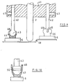
- a device for removing bumps from sheet metal contains a holder 1, which is not explained in detail in the simplified representation of FIG.
- a tension element 2 is mounted axially displaceable.
- the tension member 2 is made of metal and can thereby be bumped 3 are connected in a piece of sheet metal, that it welded to the sheet metal becomes. In place of a weld is also an attachment with the help an adhesive possible.
- the holder 1 contains a total of four, for example made of sheet metal legs 4, wherein in each case a pair of legs 4 by a Pin 5 is connected. At each pin 5, a support member 6 is attached, with the help of the right in Figure 1 to see staple 7. Die Clamp 7 is screwed by means of a screw 8 on the recording.
- the Clamp 7 practically forms the receptacle of the support element 6 for a counter element the holder 1, namely the pin 5 in the example shown.
- the support member 6 is by attachment to the pin 5 to the Axis pivotable.
- the pivotability is due to the shape of the ends the legs 4 limited.
- the ends of the legs 4 extend in the central area along a circular arc 9, which laterally merges into a tangent 10.
- the ends the legs 4 lie with the arcuate portion 9 in the neutral position the support elements 6 directly on the top of the support elements 6. This allows a direct pressure transfer without the participation of the recording respectively. This contact between the surface of the support elements 6 and the free end of the legs 4 remains in all possible angular positions of the supporting elements 6 received.
- FIG 2 shows a section along line II-II in Figure 1.
- the support elements. 6 have the shape of elongated plates, their mutually facing inner edges are cut out arcuately. This should take into account the fact be worn that the bumps in supervision are usually circular.
- the Clamps 7, each of which support member 6 has two are arranged so that they engage adjacent to the legs 4 on the pin 5. Thereby is a displacement of the support elements 6 in the direction of the pin. 5 practically impossible. It is possible, the support elements 6 by pulling to release from the pin 5 and re-attach in the reverse position, so that the arcuate cutouts 12 come to lie outside. In this Case, the support could be zoomed closer to the bulge zoom.
- FIG. 3 shows an extreme example in which positions the supporting elements 6 brought in a special shape of the surface of the sheet to be machined can be. Due to the adjustment of the support elements 6 can for be taken care that they do not produce bumps or kinks again.
- FIG. 5 shows one possibility, a support element 26 made entirely of plastic manufacture, wherein the receptacle 27 for receiving the pin 5 in one piece made of plastic.
- the inner shape of the receptacle 27 corresponds the shape as used by the bracket 7.
- To facilitate the Aufspreizens provided with chamfers 28 opening are in the outside the two opening-limiting leg incisions 29 arranged, which lead to a material weakening. This will cause the spreading facilitated.
- FIG. 6 shows another support element 36, which is divided in it and thus forms two Abstweilfgnae 37, which at the top of the sheet to be machined issue. You could also say that two support elements are present, which are interconnected and a common recording have for the pin 5. Also in this embodiment is Support member 36 molded plastic and has integrally the recording 27 for the pin 5 on. The receptacle is designed in the same way as in FIG. 5, so that it will not be described again. In this embodiment are the Abstweilfpune 37 via relatively narrow webs 38 with the Recording connected to the shaft 5. This creates at this point, namely the webs 38, a kind of hinge caused by a deformation of the material the support element 36 is realized. This is an even better Adaptation to complicated shapes of the metal surfaces and a good distribution given the occurring forces.
- Figure 7 shows a way, the clamp 7 so on the recording 6 to attach, that here is another adjustment is given.
- a slot 38 is provided, which is transverse to the longitudinal direction of the Pivot 5 runs.
- the width of the slot measured perpendicular to the plane of the paper 38 corresponds to the outer diameter of the screw 8, in this case is guided from bottom to top and with a mother 39 acts together.
- the screw 8 is displaced in the slot 38 be to thereby the support member 6 relative to the pin 5 laterally move. It becomes possible, the support elements 6 closer to the machined Place the sheet to move up, or further from this point, depending the shape and size of the bulge to be pulled out.
- FIG. 8 shows a possibility, such as a receptacle on a support element in FIG a plurality of positions with the pin 5 of the holder can be connected.
- the recording has three adjacent incisions 27, which are constructed approximately as the notches 27 in the embodiment according to Figure 5 and 6. Also in this way, the support element 6 be adjusted transversely to the pulling direction, in three stages.
- Figure 9 shows a holder 41, which is formed as a solid block.
- a storage for the tension element 2 is formed, in the same Way in its own longitudinal direction can be moved.
- Parallel to that Tensile element are in the embodiment of Figure 9 in the holder 41st two rods 42 in its own longitudinal direction adjustable held in the area their free ends each have a ball head 43.
- This ball head 43 engages in ball cups 44 which are connected to the respective support element 6 are.
- the ball pans 44 have two notches 45, the free End 46 of the ball pans 44 go out. This is a spread of Ball sockets 44 possible to use the ball heads 43 can.
- the two rods 42 are in corresponding holes in the holder 41st displaceable. To their locking serve radially to the rods 42 extending Screws 47 in the holder 41. With this type of holder, it is possible to bring the support elements 6 in a starting position in which they are not in the same level. This possibility can be used to compensate for a step 48 in the sheet surface. Of course it is also possible here, the support elements in addition to to swivel around any axis. In the stepless Pivotability of the support elements around a point passing through the center the ball head 43 is formed, it makes sense on each support element. 6 to attach only a single picture.
- FIG. 10 shows a possibility such as that at the end of a rod 42 a simplified Ball head 43 is attached. While the ball pans 44 after FIG. 9 is an undercut which allows engagement of the ball heads 43; has the receptacle 49 of Figure 10 no such undercut.
- the Determination that only prevent falling of the support elements 6, can be done by that in an extending along the equator groove 50 an O-ring is inserted, the due to friction falling of the support elements 6 prevented.
Landscapes
- Engineering & Computer Science (AREA)
- Mechanical Engineering (AREA)
- Straightening Metal Sheet-Like Bodies (AREA)
- Finish Polishing, Edge Sharpening, And Grinding By Specific Grinding Devices (AREA)
- Forging (AREA)
- Registering, Tensioning, Guiding Webs, And Rollers Therefor (AREA)
- Sealing Battery Cases Or Jackets (AREA)
- Processing And Handling Of Plastics And Other Materials For Molding In General (AREA)
Abstract
Description
- Figur 1
- schematisch eine Seitenansicht einer ersten Ausführungsform;
- Figur 2
- einen Schnitt durch die Ausführungsform nach Figur 1;
- Figur 3
- die Wirkungsweise der Abstützelemente der Ausführungsform nach Figur 1;
- Figur 4
- ein Abstützelement bei einer weiteren Ausführungsform;
- Figur 5
- im Schnitt ein Abstützelement bei einer nochmals weiteren Ausführungsform;
- Figur 6
- die Darstellung eines geteilten Abstützelements;
- Figur 7
- die Möglichkeit der Verstellung einer Aufnahme an einem Abstützelement;
- Figur 8
- eine weitere Möglichkeit der Verstellbarkeit eines Abstützelements gegenüber der Halterung;
- Figur 9
- einen Schnitt zur Darstellung der Verstellbarkeit in axialer Richtung;
- Figur 10
- in vergrößertem Maßstab ein weiteres Beispiel für eine Aufnahme eines Abstützelements.
Claims (17)
- Vorrichtung zum Ausbeulen von Blech, mit1.1 einer Halterung (1, 41),1.2 einem Zugelement (2), das1.2.1 an der Halterung (1, 41) gelagert,1.2.2 dieser gegenüber mindestens linear bewegbar ausgebildet und1.2.3 mit der zu bearbeitenden Stelle des Blechs zugfest verbindbar ist, sowie mit1.3 mindestens zwei gegebenenfalls miteinander verbindbaren Abstützelementen (6, 16, 26, 36), die1.3.1 die Halterung (1, 41) gegenüber dem Blech abstützen, wobei1.3.2 mindestens ein Abstützelement (6, 16, 26, 36) in mehreren unterschiedlichen Stellungen an der Halterung (1,41) angebracht ist.
- Vorrichtung nach Anspruch 1, bei der das Abstützelement (6, 16, 26, 36) stufenlos verstellbar ist.
- Vorrichtung nach Anspruch 1 oder 2, bei der die unterschiedlichen Stellungen des Abstützelements (6, 16, 26, 36) sich in ihren Winkelstellungen um mindestens eine Achse unterscheiden.
- Vorrichtung nach einem der vorhergehenden Ansprüche, bei der die unterschiedlichen Stellungen des Abstützelements (6, 16, 26, 36) sich in ihrem Abstand längs einer Achse parallel zur Zugrichtung des Zugelements (2) unterscheiden.
- Vorrichtung nach einem der vorhergehenden Ansprüche, bei der mindestens ein Abstützelement (6, 16, 26, 36) abnehmbar an der Halterung (1, 41) angebracht ist.
- Vorrichtung nach Anspruch 5, bei der die Anbringung des Abstützelements (6, 16, 26, 36) an der Halterung (1, 41) derart ausgebildet ist, dass sie druckfest ist.
- Vorrichtung nach einem der Ansprüche 2 bis 6, bei der die stufenlose Verstellbarkeit des Abstützelements (6, 16, 26, 36) begrenzt ist.
- Vorrichtung nach einem der vorhergehenden Ansprüche, bei der das Abstützelement (6, 16, 26, 36) eine Aufnahme für ein Element der Halterung (1, 41) aufweist.
- Vorrichtung nach einem der vorhergehenden Ansprüche, bei der an der Halterung (1, 41) ein eine Achse bildender Zapfen (5) angeordnet ist.
- Vorrichtung nach einem der vorhergehenden Ansprüche, bei der an der Halterung (41) eine Stange (42) angebracht ist, deren freies Ende mit einem Zapfen oder einen Kugelkopf (43) versehen ist.
- Vorrichtung nach Anspruch 10, bei der die Aufnahme eine Kugelpfanne (44) aufweist.
- Vorrichtung nach einem der vorhergehenden Ansprüche, bei der das Abstützelement (6, 16, 26, 36) mehrere Aufnahmen aufweist.
- Vorrichtung nach einem der vorhergehenden Ansprüche, bei der eine Platte mit mehreren Aufnahmen vorgesehen ist, die sich vom Benutzer in mehrere Abstützelemente einer von ihm gewünschten Form zerteilen lässt.
- Vorrichtung nach einem der vorhergehenden Ansprüche, bei der mindestens ein Abstützelement (16, 26, 36) mindestens im Bereich seiner dem Blech zugeordneten Seite in sich verformbar ausgebildet ist.
- Vorrichtung nach einem der vorhergehenden Ansprüche, bei der mindestens ein Abstützelement (26, 36) einstückig mit seiner Aufnahme aus Kunststoff ausgebildet ist.
- Vorrichtung nach einem der vorhergehenden Ansprüche, bei der das Abstützelement (36) in sich geteilt ist.
- Vorrichtung nach einem der vorhergehenden Ansprüche, bei der die Aufnahme an dem Abstützelement (6) quer zur Zugrichtung des Zugelements (2) verstellbar angeordnet ist.
Applications Claiming Priority (2)
| Application Number | Priority Date | Filing Date | Title |
|---|---|---|---|
| DE10140923A DE10140923A1 (de) | 2001-08-14 | 2001-08-14 | Vorrichtung zum Ausbeulen von Blech |
| DE10140923 | 2001-08-14 |
Publications (2)
| Publication Number | Publication Date |
|---|---|
| EP1285704A1 true EP1285704A1 (de) | 2003-02-26 |
| EP1285704B1 EP1285704B1 (de) | 2008-10-29 |
Family
ID=7696108
Family Applications (1)
| Application Number | Title | Priority Date | Filing Date |
|---|---|---|---|
| EP02017449A Expired - Lifetime EP1285704B1 (de) | 2001-08-14 | 2002-08-03 | Vorrichtung zum Ausbeulen von Blech |
Country Status (4)
| Country | Link |
|---|---|
| EP (1) | EP1285704B1 (de) |
| AT (1) | ATE412477T1 (de) |
| DE (2) | DE10140923A1 (de) |
| DK (1) | DK1285704T3 (de) |
Cited By (1)
| Publication number | Priority date | Publication date | Assignee | Title |
|---|---|---|---|---|
| WO2021053037A1 (de) * | 2019-09-18 | 2021-03-25 | Mueller Siegbert | Ziehwerkzeug zum bearbeiten von vertiefungen eines blechbauteils, insbesondere eines kraftfahrzeugs |
Citations (4)
| Publication number | Priority date | Publication date | Assignee | Title |
|---|---|---|---|---|
| US4930335A (en) * | 1989-07-03 | 1990-06-05 | Kosei Ishihara | Lever-type auto body dent puller |
| DE9315560U1 (de) * | 1993-10-07 | 1994-01-13 | Storz GmbH, 78727 Oberndorf | Ausbeulvorrichtung |
| EP0856366A2 (de) * | 1996-12-05 | 1998-08-05 | MB Autoattrezzature S.r.l. | Vorrichtung zum Ausbeulen eingebeulter Fahrzeugkarosserieteile |
| WO2001034316A1 (de) * | 1999-11-09 | 2001-05-17 | Mv Marketing Und Vertriebs-Gmbh & Co. Kg | Klebanker, sowie vorrichtung zur verformung von karosseriebereichen |
Family Cites Families (3)
| Publication number | Priority date | Publication date | Assignee | Title |
|---|---|---|---|---|
| DE20003647U1 (de) * | 1999-11-09 | 2000-05-18 | Gabriel, Michael, 73553 Alfdorf | Dellenausziehgerät DA62000 |
| DE20000085U1 (de) * | 2000-01-04 | 2000-03-09 | Adolf Würth GmbH & Co. KG, 74653 Künzelsau | Anordnung zum Entfernen von Beulen aus Blech |
| DE10023518A1 (de) * | 2000-05-13 | 2001-11-15 | Adolf Wuerth Gmbh & Co Kg | Vorrichtung zum Entfernen von Beulen |
-
2001
- 2001-08-14 DE DE10140923A patent/DE10140923A1/de not_active Withdrawn
-
2002
- 2002-08-03 DE DE50212949T patent/DE50212949D1/de not_active Expired - Lifetime
- 2002-08-03 AT AT02017449T patent/ATE412477T1/de active
- 2002-08-03 EP EP02017449A patent/EP1285704B1/de not_active Expired - Lifetime
- 2002-08-03 DK DK02017449T patent/DK1285704T3/da active
Patent Citations (4)
| Publication number | Priority date | Publication date | Assignee | Title |
|---|---|---|---|---|
| US4930335A (en) * | 1989-07-03 | 1990-06-05 | Kosei Ishihara | Lever-type auto body dent puller |
| DE9315560U1 (de) * | 1993-10-07 | 1994-01-13 | Storz GmbH, 78727 Oberndorf | Ausbeulvorrichtung |
| EP0856366A2 (de) * | 1996-12-05 | 1998-08-05 | MB Autoattrezzature S.r.l. | Vorrichtung zum Ausbeulen eingebeulter Fahrzeugkarosserieteile |
| WO2001034316A1 (de) * | 1999-11-09 | 2001-05-17 | Mv Marketing Und Vertriebs-Gmbh & Co. Kg | Klebanker, sowie vorrichtung zur verformung von karosseriebereichen |
Cited By (1)
| Publication number | Priority date | Publication date | Assignee | Title |
|---|---|---|---|---|
| WO2021053037A1 (de) * | 2019-09-18 | 2021-03-25 | Mueller Siegbert | Ziehwerkzeug zum bearbeiten von vertiefungen eines blechbauteils, insbesondere eines kraftfahrzeugs |
Also Published As
| Publication number | Publication date |
|---|---|
| DE50212949D1 (de) | 2008-12-11 |
| DK1285704T3 (da) | 2009-03-02 |
| EP1285704B1 (de) | 2008-10-29 |
| ATE412477T1 (de) | 2008-11-15 |
| DE10140923A1 (de) | 2003-02-27 |
Similar Documents
| Publication | Publication Date | Title |
|---|---|---|
| EP0826889B1 (de) | Befestigungselement für Profilschienen | |
| DE112012007184B4 (de) | Wellenendadapter und Kugelrollspindelaufbau | |
| EP0541904A1 (de) | Tisch, insbesondere Zuricht-und Schweisstisch | |
| EP0508050A2 (de) | Gelenkband-Konsolenschelle | |
| DE3732628C1 (de) | Aufweitewerkzeug fuer hohle Werkstuecke | |
| EP0614035A1 (de) | Deckenstativ | |
| EP0445591A1 (de) | Einrichtung zum Verbinden einer Lenksäule eines Kraftfahrzeuges mit einem Wellenzapfen eines Lenkgetriebes | |
| CH618252A5 (de) | ||
| DE3000170C2 (de) | Dorn für ein zu biegendes Rohr | |
| EP0428874A2 (de) | Verbindungsstück für aus Rohren und Knotenelementen aufgebaute Konstruktionssysteme | |
| WO1994003311A1 (de) | Messerkopf, insbesondere profilmesserkopf | |
| EP0748428B1 (de) | Rohrbefestigungsvorrichtung | |
| DE69225219T2 (de) | Vorrichtung zum biegen von trägern | |
| DE4040956C2 (de) | Mutternplatte und Befestigungsvorrichtung an einer Aufbauwand eines Kraftfahrzeugs, insbesondere an einem geschlossenem Träger | |
| DE9405680U1 (de) | Geschmiedete Anschlußklemme zum lösbaren Befestigen eines Stromkabels an einem konischen Pol eines Akkumulators | |
| DE2133446C3 (de) | ||
| CH635273A5 (de) | Vorrichtung zum loesbaren befestigen von werkstuecken an einem arbeitstisch. | |
| EP1285704B1 (de) | Vorrichtung zum Ausbeulen von Blech | |
| CH633601A5 (de) | Vorrichtung zum verbinden eines rohrendes mit einem andern rohr oder einer stange. | |
| DE69512375T2 (de) | Vorrichtung um einen Heizkörper an einer Unterlage zu befestigen | |
| DE8712119U1 (de) | Knotenelement zur Verbindung von Stabelementen | |
| DE29805542U1 (de) | Gelenkkörper, insbesondere zur schwenkbaren Befestigung eines Monitors | |
| DE4338179C2 (de) | Hebelspannzwinge | |
| DE69835283T2 (de) | Wagenheber | |
| DE19932037C1 (de) | Spannelement zum Festspannen von Teilen mit unterschiedlichen Dicken |
Legal Events
| Date | Code | Title | Description |
|---|---|---|---|
| PUAI | Public reference made under article 153(3) epc to a published international application that has entered the european phase |
Free format text: ORIGINAL CODE: 0009012 |
|
| AK | Designated contracting states |
Kind code of ref document: A1 Designated state(s): AT BE BG CH CY CZ DE DK EE ES FI FR GB GR IE IT LI LU MC NL PT SE SK TR Designated state(s): AT BE BG CH CY CZ DE DK EE ES FI FR GB GR IE IT LI LU MC NL PT SE SK TR |
|
| AX | Request for extension of the european patent |
Extension state: AL LT LV MK RO SI |
|
| 17P | Request for examination filed |
Effective date: 20030702 |
|
| AKX | Designation fees paid |
Designated state(s): AT BE BG CH CY CZ DE DK EE ES FI FR GB GR IE IT LI LU MC NL PT SE SK TR |
|
| 17Q | First examination report despatched |
Effective date: 20041026 |
|
| GRAP | Despatch of communication of intention to grant a patent |
Free format text: ORIGINAL CODE: EPIDOSNIGR1 |
|
| GRAS | Grant fee paid |
Free format text: ORIGINAL CODE: EPIDOSNIGR3 |
|
| 17Q | First examination report despatched |
Effective date: 20041026 |
|
| GRAA | (expected) grant |
Free format text: ORIGINAL CODE: 0009210 |
|
| AK | Designated contracting states |
Kind code of ref document: B1 Designated state(s): AT BE BG CH CY CZ DE DK EE ES FI FR GB GR IE IT LI LU MC NL PT SE SK TR |
|
| REG | Reference to a national code |
Ref country code: GB Ref legal event code: FG4D Free format text: NOT ENGLISH |
|
| REG | Reference to a national code |
Ref country code: CH Ref legal event code: EP |
|
| REG | Reference to a national code |
Ref country code: IE Ref legal event code: FG4D Free format text: LANGUAGE OF EP DOCUMENT: GERMAN |
|
| REF | Corresponds to: |
Ref document number: 50212949 Country of ref document: DE Date of ref document: 20081211 Kind code of ref document: P |
|
| REG | Reference to a national code |
Ref country code: CH Ref legal event code: NV Representative=s name: ZIMMERLI, WAGNER & PARTNER AG |
|
| REG | Reference to a national code |
Ref country code: DK Ref legal event code: T3 |
|
| PG25 | Lapsed in a contracting state [announced via postgrant information from national office to epo] |
Ref country code: BG Free format text: LAPSE BECAUSE OF FAILURE TO SUBMIT A TRANSLATION OF THE DESCRIPTION OR TO PAY THE FEE WITHIN THE PRESCRIBED TIME-LIMIT Effective date: 20090129 Ref country code: ES Free format text: LAPSE BECAUSE OF FAILURE TO SUBMIT A TRANSLATION OF THE DESCRIPTION OR TO PAY THE FEE WITHIN THE PRESCRIBED TIME-LIMIT Effective date: 20090209 |
|
| PG25 | Lapsed in a contracting state [announced via postgrant information from national office to epo] |
Ref country code: FI Free format text: LAPSE BECAUSE OF FAILURE TO SUBMIT A TRANSLATION OF THE DESCRIPTION OR TO PAY THE FEE WITHIN THE PRESCRIBED TIME-LIMIT Effective date: 20081029 Ref country code: PT Free format text: LAPSE BECAUSE OF FAILURE TO SUBMIT A TRANSLATION OF THE DESCRIPTION OR TO PAY THE FEE WITHIN THE PRESCRIBED TIME-LIMIT Effective date: 20090330 |
|
| REG | Reference to a national code |
Ref country code: IE Ref legal event code: FD4D |
|
| PG25 | Lapsed in a contracting state [announced via postgrant information from national office to epo] |
Ref country code: IE Free format text: LAPSE BECAUSE OF FAILURE TO SUBMIT A TRANSLATION OF THE DESCRIPTION OR TO PAY THE FEE WITHIN THE PRESCRIBED TIME-LIMIT Effective date: 20081029 Ref country code: EE Free format text: LAPSE BECAUSE OF FAILURE TO SUBMIT A TRANSLATION OF THE DESCRIPTION OR TO PAY THE FEE WITHIN THE PRESCRIBED TIME-LIMIT Effective date: 20081029 |
|
| PG25 | Lapsed in a contracting state [announced via postgrant information from national office to epo] |
Ref country code: SE Free format text: LAPSE BECAUSE OF FAILURE TO SUBMIT A TRANSLATION OF THE DESCRIPTION OR TO PAY THE FEE WITHIN THE PRESCRIBED TIME-LIMIT Effective date: 20090129 Ref country code: CZ Free format text: LAPSE BECAUSE OF FAILURE TO SUBMIT A TRANSLATION OF THE DESCRIPTION OR TO PAY THE FEE WITHIN THE PRESCRIBED TIME-LIMIT Effective date: 20081029 |
|
| PLBE | No opposition filed within time limit |
Free format text: ORIGINAL CODE: 0009261 |
|
| STAA | Information on the status of an ep patent application or granted ep patent |
Free format text: STATUS: NO OPPOSITION FILED WITHIN TIME LIMIT |
|
| PG25 | Lapsed in a contracting state [announced via postgrant information from national office to epo] |
Ref country code: SK Free format text: LAPSE BECAUSE OF FAILURE TO SUBMIT A TRANSLATION OF THE DESCRIPTION OR TO PAY THE FEE WITHIN THE PRESCRIBED TIME-LIMIT Effective date: 20081029 |
|
| 26N | No opposition filed |
Effective date: 20090730 |
|
| REG | Reference to a national code |
Ref country code: CH Ref legal event code: PFA Owner name: ADOLF WUERTH GMBH & CO. KG Free format text: ADOLF WUERTH GMBH & CO. KG#REINHOLD-WUERTH-STRASSE 12-16#74653 KUENZELSAU (DE) -TRANSFER TO- ADOLF WUERTH GMBH & CO. KG#REINHOLD-WUERTH-STRASSE 12-16#74653 KUENZELSAU (DE) |
|
| PG25 | Lapsed in a contracting state [announced via postgrant information from national office to epo] |
Ref country code: MC Free format text: LAPSE BECAUSE OF NON-PAYMENT OF DUE FEES Effective date: 20090831 |
|
| PG25 | Lapsed in a contracting state [announced via postgrant information from national office to epo] |
Ref country code: GR Free format text: LAPSE BECAUSE OF FAILURE TO SUBMIT A TRANSLATION OF THE DESCRIPTION OR TO PAY THE FEE WITHIN THE PRESCRIBED TIME-LIMIT Effective date: 20090130 |
|
| PG25 | Lapsed in a contracting state [announced via postgrant information from national office to epo] |
Ref country code: LU Free format text: LAPSE BECAUSE OF NON-PAYMENT OF DUE FEES Effective date: 20090803 |
|
| PG25 | Lapsed in a contracting state [announced via postgrant information from national office to epo] |
Ref country code: TR Free format text: LAPSE BECAUSE OF FAILURE TO SUBMIT A TRANSLATION OF THE DESCRIPTION OR TO PAY THE FEE WITHIN THE PRESCRIBED TIME-LIMIT Effective date: 20081029 |
|
| PG25 | Lapsed in a contracting state [announced via postgrant information from national office to epo] |
Ref country code: CY Free format text: LAPSE BECAUSE OF FAILURE TO SUBMIT A TRANSLATION OF THE DESCRIPTION OR TO PAY THE FEE WITHIN THE PRESCRIBED TIME-LIMIT Effective date: 20081029 |
|
| REG | Reference to a national code |
Ref country code: CH Ref legal event code: PUE Owner name: WUERTH INTERNATIONAL AG Free format text: ADOLF WUERTH GMBH & CO. KG#REINHOLD-WUERTH-STRASSE 12-16#74653 KUENZELSAU (DE) -TRANSFER TO- WUERTH INTERNATIONAL AG#ASPERMONTSTRASSE 1#7000 CHUR (CH) |
|
| REG | Reference to a national code |
Ref country code: NL Ref legal event code: SD Effective date: 20120529 |
|
| REG | Reference to a national code |
Ref country code: FR Ref legal event code: TP Owner name: WURTH INTERNATIONAL AG, CH Effective date: 20120625 |
|
| REG | Reference to a national code |
Ref country code: GB Ref legal event code: 732E Free format text: REGISTERED BETWEEN 20121004 AND 20121010 |
|
| REG | Reference to a national code |
Ref country code: AT Ref legal event code: PC Ref document number: 412477 Country of ref document: AT Kind code of ref document: T Owner name: WUERTH INTERNATIONAL AG, CH Effective date: 20121128 |
|
| PGFP | Annual fee paid to national office [announced via postgrant information from national office to epo] |
Ref country code: GB Payment date: 20150819 Year of fee payment: 14 Ref country code: DK Payment date: 20150819 Year of fee payment: 14 |
|
| PGFP | Annual fee paid to national office [announced via postgrant information from national office to epo] |
Ref country code: AT Payment date: 20150820 Year of fee payment: 14 Ref country code: NL Payment date: 20150830 Year of fee payment: 14 |
|
| REG | Reference to a national code |
Ref country code: FR Ref legal event code: PLFP Year of fee payment: 15 |
|
| REG | Reference to a national code |
Ref country code: DK Ref legal event code: EBP Effective date: 20160831 |
|
| REG | Reference to a national code |
Ref country code: NL Ref legal event code: MM Effective date: 20160901 |
|
| REG | Reference to a national code |
Ref country code: AT Ref legal event code: MM01 Ref document number: 412477 Country of ref document: AT Kind code of ref document: T Effective date: 20160803 |
|
| GBPC | Gb: european patent ceased through non-payment of renewal fee |
Effective date: 20160803 |
|
| PG25 | Lapsed in a contracting state [announced via postgrant information from national office to epo] |
Ref country code: AT Free format text: LAPSE BECAUSE OF NON-PAYMENT OF DUE FEES Effective date: 20160803 |
|
| PG25 | Lapsed in a contracting state [announced via postgrant information from national office to epo] |
Ref country code: NL Free format text: LAPSE BECAUSE OF NON-PAYMENT OF DUE FEES Effective date: 20160901 |
|
| PG25 | Lapsed in a contracting state [announced via postgrant information from national office to epo] |
Ref country code: GB Free format text: LAPSE BECAUSE OF NON-PAYMENT OF DUE FEES Effective date: 20160803 Ref country code: DK Free format text: LAPSE BECAUSE OF NON-PAYMENT OF DUE FEES Effective date: 20160831 |
|
| REG | Reference to a national code |
Ref country code: FR Ref legal event code: PLFP Year of fee payment: 16 |
|
| PGFP | Annual fee paid to national office [announced via postgrant information from national office to epo] |
Ref country code: BE Payment date: 20170821 Year of fee payment: 16 |
|
| REG | Reference to a national code |
Ref country code: FR Ref legal event code: PLFP Year of fee payment: 17 |
|
| REG | Reference to a national code |
Ref country code: BE Ref legal event code: MM Effective date: 20180831 |
|
| PG25 | Lapsed in a contracting state [announced via postgrant information from national office to epo] |
Ref country code: BE Free format text: LAPSE BECAUSE OF NON-PAYMENT OF DUE FEES Effective date: 20180831 |
|
| PGFP | Annual fee paid to national office [announced via postgrant information from national office to epo] |
Ref country code: IT Payment date: 20210830 Year of fee payment: 20 Ref country code: FR Payment date: 20210819 Year of fee payment: 20 |
|
| PGFP | Annual fee paid to national office [announced via postgrant information from national office to epo] |
Ref country code: CH Payment date: 20210819 Year of fee payment: 20 Ref country code: DE Payment date: 20210819 Year of fee payment: 20 |
|
| REG | Reference to a national code |
Ref country code: DE Ref legal event code: R071 Ref document number: 50212949 Country of ref document: DE |
|
| REG | Reference to a national code |
Ref country code: CH Ref legal event code: PL |