EP1285563A1 - Sämaschine - Google Patents
Sämaschine Download PDFInfo
- Publication number
- EP1285563A1 EP1285563A1 EP02018035A EP02018035A EP1285563A1 EP 1285563 A1 EP1285563 A1 EP 1285563A1 EP 02018035 A EP02018035 A EP 02018035A EP 02018035 A EP02018035 A EP 02018035A EP 1285563 A1 EP1285563 A1 EP 1285563A1
- Authority
- EP
- European Patent Office
- Prior art keywords
- sowing
- frame
- frames
- assigned
- storage container
- Prior art date
- Legal status (The legal status is an assumption and is not a legal conclusion. Google has not performed a legal analysis and makes no representation as to the accuracy of the status listed.)
- Withdrawn
Links
Images




Classifications
-
- A—HUMAN NECESSITIES
- A01—AGRICULTURE; FORESTRY; ANIMAL HUSBANDRY; HUNTING; TRAPPING; FISHING
- A01C—PLANTING; SOWING; FERTILISING
- A01C7/00—Sowing
- A01C7/06—Seeders combined with fertilising apparatus
-
- A—HUMAN NECESSITIES
- A01—AGRICULTURE; FORESTRY; ANIMAL HUSBANDRY; HUNTING; TRAPPING; FISHING
- A01B—SOIL WORKING IN AGRICULTURE OR FORESTRY; PARTS, DETAILS, OR ACCESSORIES OF AGRICULTURAL MACHINES OR IMPLEMENTS, IN GENERAL
- A01B73/00—Means or arrangements to facilitate transportation of agricultural machines or implements, e.g. folding frames to reduce overall width
- A01B73/02—Folding frames
- A01B73/04—Folding frames foldable about a horizontal axis
- A01B73/044—Folding frames foldable about a horizontal axis the axis being oriented in a longitudinal direction
-
- A—HUMAN NECESSITIES
- A01—AGRICULTURE; FORESTRY; ANIMAL HUSBANDRY; HUNTING; TRAPPING; FISHING
- A01C—PLANTING; SOWING; FERTILISING
- A01C7/00—Sowing
- A01C7/20—Parts of seeders for conducting and depositing seed
- A01C7/208—Chassis; Coupling means to a tractor or the like; Lifting means; Side markers
Definitions
- the invention relates to a seed drill according to the Preamble of claim 1.
- Such a seeder is for example in the EP 07 49 678 A1 described.
- the seed drill described there can have a maximum working width of 9m because everyone Frame area can be a maximum of 3m wide to keep the machine on transport public roads in the transport position to be able to.
- the invention has for its object a seed drill propose a larger working width of 9m has, but which can be brought into a transport position, the width of the machine is then less than or equal to 3 m is. At the same time, the max. Transport height of 4m at sufficient ground clearance must not be exceeded.
- a seed drill with a 12m working width at one Transport width when the individual parts are folded, of 3m without being too high in Transport position of the seed frame results.
- the reservoir unit in front of the side seed frame is arranged on the frame. This also means that the front and side sowing frames are relatively tight can be moved together.
- the Storage container unit at least two storage containers has that a storage container for receiving Seed and the other storage container for holding Fertilizer is provided.
- the seed at the beginning or end of a work path and / or the fertilizers over the entire working width at least approximately parallel to a cross to the direction of travel running working level is stored in the floor.
- This simultaneous insertion on a line can be done for example, by means of Hand levers can be operated one after the other. Of course it is possible that this activation also via a electronic device is done, by means of which the Means can be actuated accordingly.
- the Conveyor device at an angle below the dosing elements Direction of travel are arranged one behind the other.
- the seed drill according to FIGS. 1 to 4 has the frame 1, which is supported on the floor by wheels 2.
- the Impellers 2 are not shown by means of a Lifting device in relation to the frame 1 in an upright plane movably arranged around the frame 1 for the working position lower and raise to the transport position.
- On the Front of the frame 1 is the drawbar 3 Coupling the seeder to a traction device Agricultural tractor arranged.
- On the back of the frame 1 is by means of a not shown Coupling device a medium seed frame 4, which from the two subframes 4 ', 4' 'is arranged.
- the subframes 4 ', 4' ' are by means of swivel joints 5 to the Coupling device located on the rear frame part located, arranged and can by means of not shown Lifting elements, for example hydraulic cylinders, around the in Driving direction 6 extending axes 7 from the in Fig. 1st shown working position in the shown in Fig. 2 Transport position can be swiveled by 90 °.
- the subframes 4 ', 4' 'of the rear middle sowing frame 4 have coulters on that are not depicted.
- the swivel arms 9 can form swivel frames 9 with one another be connected.
- the swivel arms consist of the by means of Joints 10 on the frame 1 articulated inner parts 9 'and articulated by means of the joints 11 on the inner parts 9 ' outer parts 9 ''.
- actuating elements for example in the form of Hydraulic cylinders arranged, which are not shown.
- Storage container unit 11 which consists of a storage container 11 ' for seeds and a reservoir 11 'for fertilizers is arranged.
- Storage container unit 11 which consists of a storage container 11 ' for seeds and a reservoir 11 'for fertilizers is arranged.
- the swivel arms 9 are at least approximately in the in Driving direction 6 seen middle area on the seed frame 8,8 'articulated, the pivot arms 9 in the area of inner ends and / or the inner half of the lateral Sowing frame 8,8 'has a swivel joint 12.
- Each sowing frame 8,8 'and subframe 4', 4 '' is an am Storage container 11 arranged dosing (not shown) and a distribution head, not shown assigned.
- the metering elements are attached to the sowing frame 8, 8 'or Subframe 4 ', 4' 'arranged and not shown Drive wheels via a likewise not shown Transmission device driven.
- a drive wheel is used to drive the Dosing devices at least one of the front side sowing frame 8, 8 'and a drive wheel of the metering elements at least one assigned to the rear subframe 4, 4 '.
- each sowing frame 4 ', 4' ', 8, 8' are in a known manner and therefore, not shown, several coulters offset and arranged on gap. These coulters are not about illustrated distribution heads and the seed lines seeds and / or located in the storage containers 11 Fertilizers fed in an adjustable manner.
- each sowing frame or subframe has its own distributor head assigned to one of the Dosing elements of the reservoir 11 is connected. This Delivery lines are known and therefore not illustrated manner with a conveying air flow generating blower connected.
- the support arms 15 consist of the inner part 15 'and outer part 15 '' of the arms 15, each to swing frame can be summarized.
- the drill according to FIGS. 1 to 4 is after the drill 5 to 9, the swivel joint 16, which the inner Connect parts 15 'and the outer parts 15' 'of the arms in a distance from the inner end of the side frames 8, 8 ' arranged.
- Around these side frames 8, 8 'from the 5 and 7 in the in Fig. 6 and 9th Bring illustrated transport position are initially the rear subframes 4, 4 ', as in the machine according to Fig. 1 to 4 pivoted.
- the first Lifting means which between the inner part 15 and outer Part 15 '' of the arm 15 is arranged, operated so that lateral sowing frame in the position shown in Fig. 8 to bring.
- the outer parts 15 '' Swivel arms 15 in the direction of arrow 17 from the in Fig. 7 in the brought in position shown in Fig. 8.
- the inner part 15 'of the support arms 15 and the Frame 1 arranged lifting means actuated so that the inner Part 15 with the sowing frame 8, 8 'in the direction of arrow 18 from the in Fig. 8 position shown in the Fig. 9 shown Position.
Landscapes
- Life Sciences & Earth Sciences (AREA)
- Soil Sciences (AREA)
- Environmental Sciences (AREA)
- Engineering & Computer Science (AREA)
- Mechanical Engineering (AREA)
- Sowing (AREA)
Abstract
Description
- Fig. 1
- die Sämaschine in Arbeitsstellung in der Draufsicht, und in Prinzipdarstellung,
- Fig. 2
- die Sämaschine in Transportstellung in der Draufsicht und in Prinzipdarstellung,
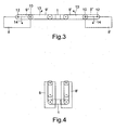
- Fig. 3
- die Anordnung der seitlichen Särahmen in Arbeitsstellung in der Ansicht III - III,
- Fig. 4
- die Anordnung der Särahmen in Transportstellung in der Ansicht III - III und in Prinzipdarstellung,
- Fig. 5
- eine weitere Sämaschine in Arbeitsstellung, in der Draufsicht, und Prinzipdarstellung,
- Fig. 6
- die Sämaschine gemäß Fig. 5 in Transportstellung, in der Draufsicht und in Prinzipdarstellung,
- Fig. 7
- die Anordnung der äußeren Särahmen in Arbeitsstellung und in der Ansicht VII - VII,
- Fig. 8
- die Darstellung der ersten Überführungsphase der äußeren Särahmen in Transportstellung in Prinzipdarstellung und in der Ansicht VII - VII und
- Fig. 9
- die Särahmen in Transportstellung in der Ansicht VII - VII.
Claims (13)
- Sämaschine mit einem sich über Laufräder auf dem Boden abstützenden Rahmen, zumindest einer Vorratsbehältereinheit und an Särahmen (4,4',4'',8,8') angeordneten Säelementen, denen das sich im Vorratsbehälter (11) befindliche Material über Dosierorgane, Fördereinrichtungen und Materialleitungen in einstellbaren Mengen zuführbar ist, wobei zumindest ein mittlerer Särahmen (4,4',4'') hinter den Laufrädern (2) und zwei seitliche Särahmen (8,8') vor den Laufrädern (2) in Fahrtrichtung (6) gesehen seitlich des mittleren Särahmens (4,4',4'') angeordnet sind, wobei die seitlichen Särahmen (8,8') jeweils mittels Schwenkarmen (9,9',9'') an dem Rahmen (1) angelenkt sind, dadurch gekennzeichnet, dass der mittlere Särahmen (4) in zwei Teilrahmen (4',4'') geteilt, wobei jeder Teilrahmen (4',4'') um eine in Fahrtrichtung (6) verlaufende Schwenkachse (7) zwischen einer Arbeits- und einer Transportsteilung verschwenkbar am Rahmen (1) angeordnet ist.
- Sämaschine nach Anspruch 1, dadurch gekennzeichnet, dass die Vorratsbehältereinheit (11) vor den seitlichen Särahmen (8,8') am Rahmen (1) angeordnet ist.
- Sämaschine nach Anspruch 1, dadurch gekennzeichnet, dass die Schwenkarme (9,9',9'') zumindest annähernd in dem in Fahrtrichtung ( 6) gesehen mittleren Bereich an dem Särahmen (8,8') angelenkt sind, dass die Schwenkarme (8,8') im Bereich der inneren Enden und/oder inneren Hälfte der seitlichen Särahmen (8,8') ein Schwenkgelenk (10) aufweisen.
- Sämaschine nach einem oder mehreren der vorstehenden Ansprüche, dadurch gekennzeichnet, dass jedem seitlichen Särahmen (8,8') und jedem Teilrahmen (4',4'') ein am Vorratsbehälter angeordnetes Dosierorgan und ein Verteilerkopf zugeordnet sind.
- Sämaschine nach einem oder mehreren der vorstehenden Ansprüche, dadurch gekennzeichnet, dass die Vorratsbehältereinheit (11) zumindest zwei Vorratsbehälter (11',11'') aufweist, dass der eine Vorratsbehälter (11') zur Aufnahme von Saatgut und der andere Vorratsbehälter (11'') zur Aufnahme von Dünger vorgesehen ist.
- Sämaschine nach einem oder mehreren der vorstehenden Ansprüche, dadurch gekennzeichnet, dass die den seitlichen Särahmen (8,8') zugeordneten Dosierorgane von einem gemeinsamen Antrieb angetrieben werden, und dass die dem hinteren Särahmen (4,4',4'') zugeordneten Dosierorgane gemeinsam angetrieben werden.
- Sämaschine nach einem oder mehreren der vorstehenden Ansprüche, dadurch gekennzeichnet, dass der Antrieb der den vorderen Särahmen (8,8') zugeordneten Dosierorgane unabhängig von den Antrieb der den hinteren Särahmen (4,4',4'') zugeordneten Dosierorgane betätigbar ist.
- Sämaschine nach einem oder mehreren der vorstehenden Ansprüche, dadurch gekennzeichnet, dass die Mittel zum Ein- und Ausschalten der den seitlichen Särahmen (8,8') zugeordneten Dosierorgane und dem Anheben und Absenken der den vorderen Särahmen (8,8') zugeordneten Betätigungselemente von einem gemeinsamen Schaltelement betätigbar sind, und dass die Mittel zum Ein- und Ausschalten der den mittleren Särahmen (4,4',4'') zugeordneten Dosierorgane und dem Anheben und Absenken der den mittleren Särahmen (4,4',4'') zugeordneten Betätigungselemente von einem gemeinsamen Schaltelement betätigbar sind.
- Sämaschine nach einem oder mehreren der vorstehenden Ansprüche, dadurch gekennzeichnet, dass Mittel vorhanden sind, mittels denen es möglich ist, dass zu Beginn bzw. zum Ende einer Arbeitsbahn das Saatgut und/oder die Düngemittel über die gesamte Arbeitsbreite zumindest annähernd parallel zu einer quer zur Fahrtrichtung verlaufenden Arbeitsebene im Boden abgelegt wird.
- Sämaschine nach einem oder mehreren der vorstehenden Ansprüche, dadurch gekennzeichnet, dass diese Mittel mittels Handhebel nacheinander betätigbar sind.
- Sämaschine nach einem oder mehreren der vorstehenden Ansprüche, dadurch gekennzeichnet, dass eine elektronische Vorrichtung vorhanden ist, mittels welcher die Mittel entsprechend betätigbar sind.
- Sämaschine nach einem oder mehreren der vorstehenden Ansprüche, dadurch gekennzeichnet, dass die Fördereinrichtungen unterhalb der Dosierorgane schräg zur Fahrtrichtung verlaufend hintereinander angeordnet sind.
- Sämaschine nach einem oder mehreren der vorstehenden Ansprüche, dadurch gekennzeichnet, dass ein Antriebsrad zum Antrieb der Dosierorgane zumindest einem der vorderen seitlichen Särahmen und ein Antriebsrad zum Antrieb der Dosierorgane zumindest einem der hinteren Särahmen zugeordnet sind.
Applications Claiming Priority (2)
| Application Number | Priority Date | Filing Date | Title |
|---|---|---|---|
| DE10140339 | 2001-08-16 | ||
| DE2001140339 DE10140339A1 (de) | 2001-08-16 | 2001-08-16 | Sämaschine |
Publications (1)
| Publication Number | Publication Date |
|---|---|
| EP1285563A1 true EP1285563A1 (de) | 2003-02-26 |
Family
ID=7695733
Family Applications (1)
| Application Number | Title | Priority Date | Filing Date |
|---|---|---|---|
| EP02018035A Withdrawn EP1285563A1 (de) | 2001-08-16 | 2002-08-13 | Sämaschine |
Country Status (2)
| Country | Link |
|---|---|
| EP (1) | EP1285563A1 (de) |
| DE (1) | DE10140339A1 (de) |
Citations (7)
| Publication number | Priority date | Publication date | Assignee | Title |
|---|---|---|---|---|
| DE4303101A1 (de) * | 1993-02-04 | 1994-08-11 | Karl Dipl Ing Deutschle | Einzelkorn-Sämaschine |
| EP0749678A1 (de) | 1995-06-22 | 1996-12-27 | Amazonen-Werke H. Dreyer GmbH & Co. KG | Sämaschine |
| EP0847683A1 (de) * | 1996-12-13 | 1998-06-17 | Gbls | Grossflächen-Drillmaschine |
| DE19833691A1 (de) * | 1998-07-27 | 2000-02-03 | Amazonen Werke Dreyer H | Baukastensystem für eine landwirtschaftliche Bestellkombination und Bestellmaschinen |
| DE19921978A1 (de) * | 1999-05-12 | 2000-11-16 | Amazonen Werke Dreyer H | Pneumatische Sämaschine |
| EP1210855A2 (de) * | 2000-12-02 | 2002-06-05 | Amazonen-Werke H. Dreyer GmbH & Co. KG | Landwirtschaftliche Bestellkombination |
| EP1210885A1 (de) * | 2000-11-23 | 2002-06-05 | LEONARDO S.r.l. | Herstellungsverfahren für ein Verbindungselement um ein Bein an eine Tischplatte zu befestigen sowie Verbindungselement gemäss genanntem Herstellungsverfahren |
-
2001
- 2001-08-16 DE DE2001140339 patent/DE10140339A1/de not_active Withdrawn
-
2002
- 2002-08-13 EP EP02018035A patent/EP1285563A1/de not_active Withdrawn
Patent Citations (7)
| Publication number | Priority date | Publication date | Assignee | Title |
|---|---|---|---|---|
| DE4303101A1 (de) * | 1993-02-04 | 1994-08-11 | Karl Dipl Ing Deutschle | Einzelkorn-Sämaschine |
| EP0749678A1 (de) | 1995-06-22 | 1996-12-27 | Amazonen-Werke H. Dreyer GmbH & Co. KG | Sämaschine |
| EP0847683A1 (de) * | 1996-12-13 | 1998-06-17 | Gbls | Grossflächen-Drillmaschine |
| DE19833691A1 (de) * | 1998-07-27 | 2000-02-03 | Amazonen Werke Dreyer H | Baukastensystem für eine landwirtschaftliche Bestellkombination und Bestellmaschinen |
| DE19921978A1 (de) * | 1999-05-12 | 2000-11-16 | Amazonen Werke Dreyer H | Pneumatische Sämaschine |
| EP1210885A1 (de) * | 2000-11-23 | 2002-06-05 | LEONARDO S.r.l. | Herstellungsverfahren für ein Verbindungselement um ein Bein an eine Tischplatte zu befestigen sowie Verbindungselement gemäss genanntem Herstellungsverfahren |
| EP1210855A2 (de) * | 2000-12-02 | 2002-06-05 | Amazonen-Werke H. Dreyer GmbH & Co. KG | Landwirtschaftliche Bestellkombination |
Also Published As
| Publication number | Publication date |
|---|---|
| DE10140339A1 (de) | 2003-02-27 |
Similar Documents
| Publication | Publication Date | Title |
|---|---|---|
| DE102017120948B4 (de) | Gezogenes landwirtschaftliches Arbeitsgerät | |
| DE3105639A1 (de) | "geraetekombination fuer die landwirtschaft" | |
| DE19833691A1 (de) | Baukastensystem für eine landwirtschaftliche Bestellkombination und Bestellmaschinen | |
| DE2528930A1 (de) | Tragrahmen fuer landwirtschaftliche maschinen und geraete | |
| DE60224766T2 (de) | Traggestell für Mäher | |
| DE2557753A1 (de) | Bodenbearbeitungs- und drillmaschine | |
| DE19620016A1 (de) | Landwirtschaftliche Bestellkombination | |
| DE69516358T2 (de) | Umkehrpflug/bodenaufbereitungskombination | |
| EP0201048B1 (de) | Geschlossene Gerätekombination für die Landwirtschaft | |
| DE1904273A1 (de) | Einzelkornsaemaschine | |
| DE2622444A1 (de) | Anbauvorrichtung fuer landwirtschaftliche verteilmaschinen | |
| DE69420316T2 (de) | Sämaschine mit einer Vorrichtung zur Begrenzung der Tiefe von Säscharen im Boden, und eine kombinierte Landmaschine bestehend aus einer Bodenbearbeitungsmaschine und eine Sämaschine mit Verwendung einer solcher Sämaschine | |
| DE19954423A1 (de) | Landwirtschaftliche Bestellkombination mit günstiger Schwerpunktsverlagerung | |
| DE2559341C3 (de) | Maschine zum Ausbringen von Dänger und Saatgut | |
| EP1763983B1 (de) | Landwirtschaftliches Gerät | |
| DE4002172C1 (en) | Agricultural implement for preparing soil - has self propelled vehicle with platform which has movable working arm | |
| EP2371194B1 (de) | Vorrichtung zum Verteilen von Saatgut und/oder Dünger | |
| EP0993762B1 (de) | Gezogene landwirtschaftliche Verteilmaschine | |
| DE8104256U1 (de) | Zusammengeschlossene geraetekombination fuer die landwirtschaft | |
| DE10140339A1 (de) | Sämaschine | |
| DE2628798B2 (de) | Anbauvorrichtung für Schleuderdüngerstreuer | |
| EP0752202A2 (de) | Tragrahmen für landwirtschaftliche Bodenbearbeitungs- und/oder Bestellkombination | |
| DE19821394A1 (de) | Gezogene landwirtschaftliche Bestellkombination | |
| DE19933900A1 (de) | Landwirtschaftliche Bestellkombination | |
| DE69424828T2 (de) | Gerätekombination zur Bodenbearbeitung und zum Säen deren Sämaschine während des Transportes gut gehalten ist |
Legal Events
| Date | Code | Title | Description |
|---|---|---|---|
| PUAI | Public reference made under article 153(3) epc to a published international application that has entered the european phase |
Free format text: ORIGINAL CODE: 0009012 |
|
| AK | Designated contracting states |
Kind code of ref document: A1 Designated state(s): AT BE BG CH CY CZ DE DK EE ES FI FR GB GR IE IT LI LU MC NL PT SE SK TR Designated state(s): AT BE BG CH CY CZ DE DK EE ES FI FR GB GR IE IT LI LU MC NL PT SE SK TR |
|
| AX | Request for extension of the european patent |
Extension state: AL LT LV MK RO SI |
|
| 17P | Request for examination filed |
Effective date: 20030710 |
|
| 17Q | First examination report despatched |
Effective date: 20030905 |
|
| AKX | Designation fees paid |
Designated state(s): AT BE BG CH CY CZ DE DK EE ES FI FR GB GR IE IT LI LU MC NL PT SE SK TR |
|
| STAA | Information on the status of an ep patent application or granted ep patent |
Free format text: STATUS: THE APPLICATION IS DEEMED TO BE WITHDRAWN |
|
| 18D | Application deemed to be withdrawn |
Effective date: 20040506 |