EP1285142B1 - Selbstreinigende vorrichtung, insbesondere für abwasserrechen - Google Patents
Selbstreinigende vorrichtung, insbesondere für abwasserrechen Download PDFInfo
- Publication number
- EP1285142B1 EP1285142B1 EP01930342A EP01930342A EP1285142B1 EP 1285142 B1 EP1285142 B1 EP 1285142B1 EP 01930342 A EP01930342 A EP 01930342A EP 01930342 A EP01930342 A EP 01930342A EP 1285142 B1 EP1285142 B1 EP 1285142B1
- Authority
- EP
- European Patent Office
- Prior art keywords
- grate
- screenings
- pickup
- screening
- carrier belts
- Prior art date
- Legal status (The legal status is an assumption and is not a legal conclusion. Google has not performed a legal analysis and makes no representation as to the accuracy of the status listed.)
- Expired - Lifetime
Links
- 238000012216 screening Methods 0.000 title claims abstract description 58
- 239000010813 municipal solid waste Substances 0.000 title claims abstract description 16
- 238000004140 cleaning Methods 0.000 title claims abstract description 6
- 239000007788 liquid Substances 0.000 claims abstract description 15
- 230000007423 decrease Effects 0.000 claims description 2
- 210000001520 comb Anatomy 0.000 claims 1
- XLYOFNOQVPJJNP-UHFFFAOYSA-N water Substances O XLYOFNOQVPJJNP-UHFFFAOYSA-N 0.000 description 5
- 238000000034 method Methods 0.000 description 4
- 238000005452 bending Methods 0.000 description 1
- 230000001955 cumulated effect Effects 0.000 description 1
- 125000004122 cyclic group Chemical group 0.000 description 1
- 239000003651 drinking water Substances 0.000 description 1
- 235000020188 drinking water Nutrition 0.000 description 1
- 239000000284 extract Substances 0.000 description 1
- 238000012423 maintenance Methods 0.000 description 1
- 239000002184 metal Substances 0.000 description 1
- 239000002245 particle Substances 0.000 description 1
Images

Classifications
-
- E—FIXED CONSTRUCTIONS
- E02—HYDRAULIC ENGINEERING; FOUNDATIONS; SOIL SHIFTING
- E02B—HYDRAULIC ENGINEERING
- E02B8/00—Details of barrages or weirs ; Energy dissipating devices carried by lock or dry-dock gates
- E02B8/02—Sediment base gates; Sand sluices; Structures for retaining arresting waterborne material
- E02B8/023—Arresting devices for waterborne materials
- E02B8/026—Cleaning devices
Definitions
- the invention relates to liquid cleaning equipment of the mechanical screening type.
- Trash screens are widely used at water intakes of different purpose, either industrial or those related to drinking water for communal use. They are intended to mechanically stop rubbish enter intake pumps so as to avoid pump malfunctioning, choking or even damage. Trash screens of different types are described in the book “Urzadzenia do uzdatniania wody - zasady réelleowania i przykady oblicze " (Equipment for water treatment - principles of design and calculation examples) by Zbigniew Heidrick, issued in Poland by Arkady publishing house in 198 7, pages 139 to 143.
- Trash screens take the form of grates, screens or micro-screen. With respect to their design trash screens can be divided into two groups: stationary and replaceable. Depending on the method of removing the cumulated screenings trash screens can be classified as cleaned manually or mechanically, the latter applicable particularly at large water intakes.
- Known trash screens that are installed at water intake windows are built as frames with vertical or horizontal rods running across, the proper clearance between adjacent rods left, depending on the size of rubbish particles that have to be stopped.
- the present invention is aimed at providing a trash screen that is mechanically self-cleaned in such a way that a long unattended operating period is ensured.
- a device according to the preamble of the appended claim is known from DE-A-2 521 536.
- the device comprises a screening grate made in the form of a frame that is favourably out of plumb with its top edge down the liquid flow.
- Parallel grating bars are arranged in the frame plane, running from the bottom to the top.
- a screenings container is placed, whose one side wall is so fixed that it can rotate around its bottom edge while sticking with its top edge to the grate across the whole grate width.
- a system of two carrier belts is arranged, guided along the side edges of the grate.
- a number of screenings pickups are arranged across the grate bars, attached with their ends to the carrier belts and moved along the bars from the bottom towards the top of the grate as the carrier belts travel.
- Each screenings pickup is made in the form of a comb whose teeth enter the clearances between the grate bars, and their parts protruding into the opposite side of the grate make the working part of the screenings pickup which extracts screenings deposited on the bars and picks them up over the liquid level.
- the active parts of the pickup teeth make an obtuse angle with the plane of that grate part which is above the particular pickup.
- the carrier belts of the pickups are deflected from the grate plane in their section running above the screenings container, so that the length of the working part of pickup teeth decreases as the pickup is moved upwards, until the pickup teeth are entirely withdrawn from between the grate bars when the pickup reaches a position near the top edge of the grate.
- the advantage of a screening grate formed in accordance with the invention consists in the avoidance of earlier mentioned inconvenience of the necessity of periodical removal of deposited screenings by providing a mechanism of cyclic self-cleaning. Resulting from that, high device reliability can be achieved and its maintenance minimised.
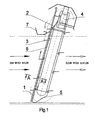
- Figure 1 shows screening grate 1, which is made of a rectangular frame with parallel round bars and a clearance between them chosen properly to the trash size that has to be stopped.
- the bars are attached with their ends to the bottom and top edges of the frame and have no joints between them along all their length.
- Grate 1 is favourably out of plumb with its top edge down the liquid flow.
- screenings container 7 Before the grate, above the surface of in-flowing raw liquid, screenings container 7 is arranged, whose one side wall is so fixed that it can rotate around its bottom edge while its top edge sticks to grate 1. After the grate, on the clean liquid outflow side, a drive system of two rubber carrier belts 2 is provided, driven by a pair of toothed wheels 4. The drive system and the grate are mounted on common supporting structure 5.
- Screenings pickups 3 are mounted to carrier belts 2 at some regular distances between them, stretched between the belts across the bars of grate 1.
- Screenings pickup 3 is made in form of a sheet-metal section with the bottom of the section made wider; the crosswise recesses in the bottom of the pickup take the form of a comb whose teeth enter the clearances between the grate bars, and protrude into the opposite side of grate 1, making the working part of screenings pickup 3.
- the plane of the working part of screenings pickup 3 makes favourably an obtuse angle with the plane of that part of grate 1 which is above the particular screenings pickup.
- Supporting-and-fixing plate 8 is secured to the surface of screenings pickup 3, having recesses on one of its longer sides so shaped as to match the cross section of the grate bars. Supporting-and-fixing plates 8 of several adjacent screenings pickups 3 are in touch with grate 1 at a time, thus making a support for its bars and fixing the clearance between the bars, which is especially important when grates are built of long bars, which are susceptible to bending by water flow carrying a large amount of rubbish.
- Carrier belts 2 are guided by means of slide ways 6 that run along the side edges of grate 1 up to the level of screenings container 7 and around the bottom arc.
- the length of the working part of screenings pickup 3 remains constant during its upward travel along the grate section that is below screenings container 7, but it gradually shortens as screenings pickup 3 continues to move along the grate section over screenings container 7, which is because of the deflection of the way of carrier belts 2 from the surface of grate 1, until the entire withdrawal of the teeth of screenings pickup 3 from between the grate bars, which occurs when it nears the topmost position.
- the device according to this invention operates as follows. Screenings deposited on grate 1 during the liquid screening process are cyclically pushed up along the grate bars by screenings pickups 3 and picked up over the raw liquid level. When a pickup 3, on its way upwards, reaches the level of screenings container 7, it pushes the rotary wall of the latter off grate 1 and continues to carry a portion of screenings over the level of screenings container 7. At the grate section located over screenings container 7, the teeth of screenings pickup 3 are gradually withdrawn from between the grate bars as it travels upwards, which results in screenings sliding down freely along the grate bars and falling into screenings container 7 whose rotary wall sticks with its upper edge to grate 1.
- the properly adjusted obtuse angle between the plane of the working teeth of screenings pickup 3 and the part of grate plane 1 which is above the screenings pickup facilitates the process of cleaning the immersed part of grate 1 by creating a force component that tears screenings off the grate surface.
Landscapes
- Engineering & Computer Science (AREA)
- General Engineering & Computer Science (AREA)
- Mechanical Engineering (AREA)
- Civil Engineering (AREA)
- Structural Engineering (AREA)
- Separation Of Solids By Using Liquids Or Pneumatic Power (AREA)
- Cleaning By Liquid Or Steam (AREA)
- Measuring Or Testing Involving Enzymes Or Micro-Organisms (AREA)
- Detergent Compositions (AREA)
- Accessories Of Cameras (AREA)
- Removal Of Floating Material (AREA)
- Paper (AREA)
- Filters For Electric Vacuum Cleaners (AREA)
- Cleaning And De-Greasing Of Metallic Materials By Chemical Methods (AREA)
Claims (1)
- Selbstreinigende Vorrichtung, insbesondere für Abwasserrechen, die einen Einlaufrechen (1) in Form eines Rahmens mit einem Satz in einer Ebene von unten nach oben parallel verlaufenden, vorzugsweise aus Blei bestehenden Stangen aufweist, deren obere Kante im Flüssigkeitsstrom liegt, sowie einen Rechbehälter (7) und einen Satz Rechenaufnehmer (3), deren Enden auf einem System von Trägerriemen (2) angebracht sind, umfaßt, wobei das System von Trägerriemen (2) hinter dem Einlaufrechen (1) auf der Reinflüssigkeitsseite liegt und die Rechaufnehmer (3) in Form von Kämmen, deren Zähne zwischen den Stangen des Einlaufrechens (1) eintreten, gelegen ist, dadurch gekennzeichnet, daß die Ebene, in der die Zähne der Rechaufnehmer (3) in Gegenrichtung zum Einlaufrechen (1) liegen, einen stumpfen Winkel mit dem Teil der Oberfläche des Einlaufrechens (1) bildet, die über dem Rechaufnehmer (3) liegt, und daß die Trägerriemen (2) von der Ebene des Einlaufrechens (1) in den Teil über den Rechbehälter (7) abgelenkt werden, so daß die Länge der in Gegenrichtung zum Einlaufrechen (1) vorstehenden Rechaufnahmezähne mit Zunahme der Positionshöhe der Rechaufnehmer (3) abnimmt.
Applications Claiming Priority (3)
| Application Number | Priority Date | Filing Date | Title |
|---|---|---|---|
| PL34014200 | 2000-05-15 | ||
| PL340142A PL194073B1 (pl) | 2000-05-15 | 2000-05-15 | Urządzenie samoczyszczące, zwłaszcza do zgrubnego oczyszczania cieczy |
| PCT/PL2001/000043 WO2001088291A1 (en) | 2000-05-15 | 2001-05-15 | Self-cleaning device, especially for trash screening |
Publications (2)
| Publication Number | Publication Date |
|---|---|
| EP1285142A1 EP1285142A1 (de) | 2003-02-26 |
| EP1285142B1 true EP1285142B1 (de) | 2003-12-10 |
Family
ID=20076635
Family Applications (1)
| Application Number | Title | Priority Date | Filing Date |
|---|---|---|---|
| EP01930342A Expired - Lifetime EP1285142B1 (de) | 2000-05-15 | 2001-05-15 | Selbstreinigende vorrichtung, insbesondere für abwasserrechen |
Country Status (7)
| Country | Link |
|---|---|
| EP (1) | EP1285142B1 (de) |
| AT (1) | ATE256227T1 (de) |
| AU (1) | AU2001256878A1 (de) |
| DE (1) | DE60101473T2 (de) |
| DK (1) | DK1285142T3 (de) |
| PL (1) | PL194073B1 (de) |
| WO (1) | WO2001088291A1 (de) |
Cited By (1)
| Publication number | Priority date | Publication date | Assignee | Title |
|---|---|---|---|---|
| DE102017003243B4 (de) | 2017-04-04 | 2018-10-25 | Iconex KG | Vorrichtung zur Befestigung an einem Einkaufsbehälter, System und Verfahren zur Überwachung eines Einkaufsbehälters |
Families Citing this family (2)
| Publication number | Priority date | Publication date | Assignee | Title |
|---|---|---|---|---|
| FR2857994B1 (fr) * | 2003-07-25 | 2006-11-10 | Roumen Kaltchev | Dispositif de degrillage/tamisage d'un liquide charge en corps volumineux, et procede de degrillage/tamisage d'un tel liquide mettant en oeuvre ce dispositif |
| PL444636A1 (pl) * | 2023-04-25 | 2024-10-28 | Zygmunt Czekała | Samoczyszcząca zmechanizowana krata, zwłaszcza do oczyszczania ścieków |
Family Cites Families (2)
| Publication number | Priority date | Publication date | Assignee | Title |
|---|---|---|---|---|
| DE2921536C3 (de) * | 1979-05-28 | 1982-03-18 | Rompf Klärwerkeinrichtungen GmbH, 6349 Driedorf | Reinigungsvorrichtung für einen in einen Kanal eingebauten Rechenrost |
| FR2657635B1 (fr) * | 1990-01-31 | 1992-07-31 | Eau Gaz Assain | Degrilleur aval, ejectant par l'amont, comportant un peigne articule qui descend, escamote, et remonte, ouvert horizontalement en degrillant, et un deversoir mobile amont. |
-
2000
- 2000-05-15 PL PL340142A patent/PL194073B1/pl unknown
-
2001
- 2001-05-15 EP EP01930342A patent/EP1285142B1/de not_active Expired - Lifetime
- 2001-05-15 AU AU2001256878A patent/AU2001256878A1/en not_active Abandoned
- 2001-05-15 AT AT01930342T patent/ATE256227T1/de not_active IP Right Cessation
- 2001-05-15 DK DK01930342T patent/DK1285142T3/da active
- 2001-05-15 WO PCT/PL2001/000043 patent/WO2001088291A1/en not_active Ceased
- 2001-05-15 DE DE60101473T patent/DE60101473T2/de not_active Expired - Lifetime
Cited By (1)
| Publication number | Priority date | Publication date | Assignee | Title |
|---|---|---|---|---|
| DE102017003243B4 (de) | 2017-04-04 | 2018-10-25 | Iconex KG | Vorrichtung zur Befestigung an einem Einkaufsbehälter, System und Verfahren zur Überwachung eines Einkaufsbehälters |
Also Published As
| Publication number | Publication date |
|---|---|
| DK1285142T3 (da) | 2004-04-13 |
| ATE256227T1 (de) | 2003-12-15 |
| AU2001256878A1 (en) | 2001-11-26 |
| DE60101473T2 (de) | 2004-10-14 |
| WO2001088291A1 (en) | 2001-11-22 |
| PL194073B1 (pl) | 2007-04-30 |
| PL340142A1 (en) | 2000-11-06 |
| DE60101473D1 (de) | 2004-01-22 |
| EP1285142A1 (de) | 2003-02-26 |
Similar Documents
| Publication | Publication Date | Title |
|---|---|---|
| KR100987812B1 (ko) | 로타리식 자동 제진기 | |
| KR101099431B1 (ko) | 로타리 제진기 | |
| KR102161407B1 (ko) | 스크린협잡물 제거장치 | |
| KR101887831B1 (ko) | 협잡물 퇴적방지구조가 적용된 계단식 여과기 | |
| EP1285142B1 (de) | Selbstreinigende vorrichtung, insbesondere für abwasserrechen | |
| KR101331968B1 (ko) | 커터장치가 설치된 로타리 제진기 | |
| CN106430373A (zh) | 一种回转耙式格栅除污设备 | |
| CN110777748B (zh) | 一种河道治理垃圾拦截处理方法 | |
| RU2283190C2 (ru) | Скребковая система чистки мусорозадерживающей решетки (варианты) и способ чистки мусорозадерживающей решетки для очистки воды | |
| US1920158A (en) | Apparatus | |
| KR102516599B1 (ko) | 인양이 용이한 이동식 제진기 | |
| RU2253717C2 (ru) | Устройство для задержания и удаления механических примесей из сточных вод | |
| KR100649667B1 (ko) | 갈퀴청소구가 설치된 배수로용 오물수거장치 | |
| KR101222075B1 (ko) | 수중 부유물 제거장치 | |
| KR100890554B1 (ko) | 제진기의 전위스크린 | |
| KR200351873Y1 (ko) | 보조 스크린이 설치된 제진기 | |
| KR100746924B1 (ko) | 협잡물 제거용 로타리 자동스크린 | |
| US2128346A (en) | Bar screen scraper | |
| CN212506160U (zh) | 一种抽水蓄能电站拦污装置 | |
| KR101746463B1 (ko) | 스크린 배면청소유니트가 구비된 제진기 | |
| KR200381939Y1 (ko) | 협잡물 제거용 로타리 자동스크린 | |
| JPH0514216U (ja) | 除塵機 | |
| RU2566448C1 (ru) | Устройство для очистки сороудерживающей решетки | |
| JPH08912A (ja) | 沈澱分離装置 | |
| EP4085989A1 (de) | Filtervorrichtung |
Legal Events
| Date | Code | Title | Description |
|---|---|---|---|
| PUAI | Public reference made under article 153(3) epc to a published international application that has entered the european phase |
Free format text: ORIGINAL CODE: 0009012 |
|
| 17P | Request for examination filed |
Effective date: 20021210 |
|
| AK | Designated contracting states |
Kind code of ref document: A1 Designated state(s): AT BE CH CY DE DK ES FI FR GB GR IE IT LI LU MC NL PT SE TR |
|
| AX | Request for extension of the european patent |
Extension state: AL LT LV MK RO SI |
|
| GRAH | Despatch of communication of intention to grant a patent |
Free format text: ORIGINAL CODE: EPIDOS IGRA |
|
| GRAS | Grant fee paid |
Free format text: ORIGINAL CODE: EPIDOSNIGR3 |
|
| GRAA | (expected) grant |
Free format text: ORIGINAL CODE: 0009210 |
|
| AK | Designated contracting states |
Kind code of ref document: B1 Designated state(s): AT BE CH CY DE DK ES FI FR GB GR IE IT LI LU MC NL PT SE TR |
|
| PG25 | Lapsed in a contracting state [announced via postgrant information from national office to epo] |
Ref country code: IT Free format text: LAPSE BECAUSE OF FAILURE TO SUBMIT A TRANSLATION OF THE DESCRIPTION OR TO PAY THE FEE WITHIN THE PRESCRIBED TIME-LIMIT;WARNING: LAPSES OF ITALIAN PATENTS WITH EFFECTIVE DATE BEFORE 2007 MAY HAVE OCCURRED AT ANY TIME BEFORE 2007. THE CORRECT EFFECTIVE DATE MAY BE DIFFERENT FROM THE ONE RECORDED. Effective date: 20031210 Ref country code: BE Free format text: LAPSE BECAUSE OF FAILURE TO SUBMIT A TRANSLATION OF THE DESCRIPTION OR TO PAY THE FEE WITHIN THE PRESCRIBED TIME-LIMIT Effective date: 20031210 Ref country code: FI Free format text: LAPSE BECAUSE OF FAILURE TO SUBMIT A TRANSLATION OF THE DESCRIPTION OR TO PAY THE FEE WITHIN THE PRESCRIBED TIME-LIMIT Effective date: 20031210 Ref country code: CY Free format text: LAPSE BECAUSE OF FAILURE TO SUBMIT A TRANSLATION OF THE DESCRIPTION OR TO PAY THE FEE WITHIN THE PRESCRIBED TIME-LIMIT Effective date: 20031210 Ref country code: LI Free format text: LAPSE BECAUSE OF FAILURE TO SUBMIT A TRANSLATION OF THE DESCRIPTION OR TO PAY THE FEE WITHIN THE PRESCRIBED TIME-LIMIT Effective date: 20031210 Ref country code: NL Free format text: LAPSE BECAUSE OF FAILURE TO SUBMIT A TRANSLATION OF THE DESCRIPTION OR TO PAY THE FEE WITHIN THE PRESCRIBED TIME-LIMIT Effective date: 20031210 Ref country code: AT Free format text: LAPSE BECAUSE OF FAILURE TO SUBMIT A TRANSLATION OF THE DESCRIPTION OR TO PAY THE FEE WITHIN THE PRESCRIBED TIME-LIMIT Effective date: 20031210 Ref country code: TR Free format text: LAPSE BECAUSE OF FAILURE TO SUBMIT A TRANSLATION OF THE DESCRIPTION OR TO PAY THE FEE WITHIN THE PRESCRIBED TIME-LIMIT Effective date: 20031210 Ref country code: CH Free format text: LAPSE BECAUSE OF FAILURE TO SUBMIT A TRANSLATION OF THE DESCRIPTION OR TO PAY THE FEE WITHIN THE PRESCRIBED TIME-LIMIT Effective date: 20031210 |
|
| REG | Reference to a national code |
Ref country code: GB Ref legal event code: FG4D |
|
| REG | Reference to a national code |
Ref country code: CH Ref legal event code: EP |
|
| REG | Reference to a national code |
Ref country code: IE Ref legal event code: FG4D |
|
| REF | Corresponds to: |
Ref document number: 60101473 Country of ref document: DE Date of ref document: 20040122 Kind code of ref document: P |
|
| PG25 | Lapsed in a contracting state [announced via postgrant information from national office to epo] |
Ref country code: GR Free format text: LAPSE BECAUSE OF FAILURE TO SUBMIT A TRANSLATION OF THE DESCRIPTION OR TO PAY THE FEE WITHIN THE PRESCRIBED TIME-LIMIT Effective date: 20040310 Ref country code: SE Free format text: LAPSE BECAUSE OF FAILURE TO SUBMIT A TRANSLATION OF THE DESCRIPTION OR TO PAY THE FEE WITHIN THE PRESCRIBED TIME-LIMIT Effective date: 20040310 |
|
| PG25 | Lapsed in a contracting state [announced via postgrant information from national office to epo] |
Ref country code: ES Free format text: LAPSE BECAUSE OF FAILURE TO SUBMIT A TRANSLATION OF THE DESCRIPTION OR TO PAY THE FEE WITHIN THE PRESCRIBED TIME-LIMIT Effective date: 20040321 |
|
| REG | Reference to a national code |
Ref country code: DK Ref legal event code: T3 |
|
| PG25 | Lapsed in a contracting state [announced via postgrant information from national office to epo] |
Ref country code: LU Free format text: LAPSE BECAUSE OF NON-PAYMENT OF DUE FEES Effective date: 20040515 |
|
| PG25 | Lapsed in a contracting state [announced via postgrant information from national office to epo] |
Ref country code: IE Free format text: LAPSE BECAUSE OF NON-PAYMENT OF DUE FEES Effective date: 20040517 |
|
| LTIE | Lt: invalidation of european patent or patent extension |
Effective date: 20031210 |
|
| PG25 | Lapsed in a contracting state [announced via postgrant information from national office to epo] |
Ref country code: MC Free format text: LAPSE BECAUSE OF NON-PAYMENT OF DUE FEES Effective date: 20040531 |
|
| NLV1 | Nl: lapsed or annulled due to failure to fulfill the requirements of art. 29p and 29m of the patents act | ||
| REG | Reference to a national code |
Ref country code: CH Ref legal event code: PL |
|
| ET | Fr: translation filed | ||
| PLBE | No opposition filed within time limit |
Free format text: ORIGINAL CODE: 0009261 |
|
| STAA | Information on the status of an ep patent application or granted ep patent |
Free format text: STATUS: NO OPPOSITION FILED WITHIN TIME LIMIT |
|
| 26N | No opposition filed |
Effective date: 20040913 |
|
| REG | Reference to a national code |
Ref country code: IE Ref legal event code: MM4A |
|
| PG25 | Lapsed in a contracting state [announced via postgrant information from national office to epo] |
Ref country code: PT Free format text: LAPSE BECAUSE OF NON-PAYMENT OF DUE FEES Effective date: 20040510 |
|
| PGFP | Annual fee paid to national office [announced via postgrant information from national office to epo] |
Ref country code: DK Payment date: 20100524 Year of fee payment: 10 Ref country code: FR Payment date: 20100608 Year of fee payment: 10 |
|
| REG | Reference to a national code |
Ref country code: DK Ref legal event code: EBP |
|
| REG | Reference to a national code |
Ref country code: FR Ref legal event code: ST Effective date: 20120131 |
|
| PG25 | Lapsed in a contracting state [announced via postgrant information from national office to epo] |
Ref country code: FR Free format text: LAPSE BECAUSE OF NON-PAYMENT OF DUE FEES Effective date: 20110531 |
|
| PG25 | Lapsed in a contracting state [announced via postgrant information from national office to epo] |
Ref country code: DK Free format text: LAPSE BECAUSE OF NON-PAYMENT OF DUE FEES Effective date: 20110531 |
|
| PGFP | Annual fee paid to national office [announced via postgrant information from national office to epo] |
Ref country code: GB Payment date: 20140424 Year of fee payment: 14 |
|
| GBPC | Gb: european patent ceased through non-payment of renewal fee |
Effective date: 20150515 |
|
| PG25 | Lapsed in a contracting state [announced via postgrant information from national office to epo] |
Ref country code: GB Free format text: LAPSE BECAUSE OF NON-PAYMENT OF DUE FEES Effective date: 20150515 |
|
| PGFP | Annual fee paid to national office [announced via postgrant information from national office to epo] |
Ref country code: DE Payment date: 20180522 Year of fee payment: 18 |
|
| REG | Reference to a national code |
Ref country code: DE Ref legal event code: R119 Ref document number: 60101473 Country of ref document: DE |
|
| PG25 | Lapsed in a contracting state [announced via postgrant information from national office to epo] |
Ref country code: DE Free format text: LAPSE BECAUSE OF NON-PAYMENT OF DUE FEES Effective date: 20191203 |