EP1284585A1 - Elektroakustische Wellenleiterwandlung - Google Patents
Elektroakustische Wellenleiterwandlung Download PDFInfo
- Publication number
- EP1284585A1 EP1284585A1 EP02026327A EP02026327A EP1284585A1 EP 1284585 A1 EP1284585 A1 EP 1284585A1 EP 02026327 A EP02026327 A EP 02026327A EP 02026327 A EP02026327 A EP 02026327A EP 1284585 A1 EP1284585 A1 EP 1284585A1
- Authority
- EP
- European Patent Office
- Prior art keywords
- waveguide
- cross
- sectional area
- sections
- section
- Prior art date
- Legal status (The legal status is an assumption and is not a legal conclusion. Google has not performed a legal analysis and makes no representation as to the accuracy of the status listed.)
- Granted
Links
- 230000002463 transducing effect Effects 0.000 title 1
- 230000013011 mating Effects 0.000 claims abstract description 5
- 239000011358 absorbing material Substances 0.000 description 9
- 230000005855 radiation Effects 0.000 description 5
- 102220047090 rs6152 Human genes 0.000 description 5
- 230000015572 biosynthetic process Effects 0.000 description 3
- 239000002537 cosmetic Substances 0.000 description 2
- 230000000694 effects Effects 0.000 description 2
- 230000000712 assembly Effects 0.000 description 1
- 238000000429 assembly Methods 0.000 description 1
- 239000000919 ceramic Substances 0.000 description 1
- 238000005094 computer simulation Methods 0.000 description 1
- 230000001788 irregular Effects 0.000 description 1
Images


Classifications
-
- H—ELECTRICITY
- H04—ELECTRIC COMMUNICATION TECHNIQUE
- H04R—LOUDSPEAKERS, MICROPHONES, GRAMOPHONE PICK-UPS OR LIKE ACOUSTIC ELECTROMECHANICAL TRANSDUCERS; DEAF-AID SETS; PUBLIC ADDRESS SYSTEMS
- H04R1/00—Details of transducers, loudspeakers or microphones
- H04R1/20—Arrangements for obtaining desired frequency or directional characteristics
- H04R1/22—Arrangements for obtaining desired frequency or directional characteristics for obtaining desired frequency characteristic only
- H04R1/28—Transducer mountings or enclosures modified by provision of mechanical or acoustic impedances, e.g. resonator, damping means
- H04R1/2807—Enclosures comprising vibrating or resonating arrangements
- H04R1/2853—Enclosures comprising vibrating or resonating arrangements using an acoustic labyrinth or a transmission line
- H04R1/2857—Enclosures comprising vibrating or resonating arrangements using an acoustic labyrinth or a transmission line for loudspeaker transducers
-
- H—ELECTRICITY
- H04—ELECTRIC COMMUNICATION TECHNIQUE
- H04R—LOUDSPEAKERS, MICROPHONES, GRAMOPHONE PICK-UPS OR LIKE ACOUSTIC ELECTROMECHANICAL TRANSDUCERS; DEAF-AID SETS; PUBLIC ADDRESS SYSTEMS
- H04R1/00—Details of transducers, loudspeakers or microphones
- H04R1/20—Arrangements for obtaining desired frequency or directional characteristics
- H04R1/32—Arrangements for obtaining desired frequency or directional characteristics for obtaining desired directional characteristic only
- H04R1/34—Arrangements for obtaining desired frequency or directional characteristics for obtaining desired directional characteristic only by using a single transducer with sound reflecting, diffracting, directing or guiding means
- H04R1/345—Arrangements for obtaining desired frequency or directional characteristics for obtaining desired directional characteristic only by using a single transducer with sound reflecting, diffracting, directing or guiding means for loudspeakers
Definitions
- the invention relates to acoustic waveguide loudspeaker systems, and more particularly to those with waveguides which have non-uniform cross-sectional areas.
- WO 96/11558 discloses a waveguide system for radiating sound waves, comprising:
- such a waveguide system is characterised in a plurality of sections, along the length of said centerline, each of said sections having a first end and a second end, said first end nearer said first terminus and said second end nearer said second terminus, each of said sections having an average cross-sectional area (A 1 , A 2 ... A n ); wherein a first of said plurality of sections and a second of said plurality of sections are constructed and arranged such that there is a mating of said second end of said first section to said first end of said second section; and wherein the cross-sectional area at said second end of said first section has a substantially different cross-sectional area from that at the first end of said second section.
- a waveguide 14 has a first end or terminus 12 and a second end or terminus 16.
- Waveguide 14 is in the form of a hollow tube of narrowing cross sectional area. Walls of waveguide 14 are tapered, such that the cross-sectional area of the waveguide at first end 12 is larger than the cross-sectional area at the second end 16.
- Second end 16 may be slightly flared for acoustic or cosmetic reasons.
- the cross section (as taken along line A-A of Figure 1, perpendicular to the centerline 11 of waveguide 14) may be circular, oval, or a regular or irregular polyhedron, or some other closed contour.
- Waveguide 14 may be closed ended or open ended. Both ends may radiate into free air as shown or one end may radiate into an acoustic enclosure, such as a closed or ported volume or a tapered or untapered waveguide.
- the walls of waveguide 14 are shown as straight and waveguide 14 is shown as uniformly tapered along its entire length.
- the waveguide may be curved to be a desired shape, to fit into an enclosure, or to position one end of the waveguide relative to the other end of the waveguide for acoustical reasons.
- the cross section of waveguide 14 may be of different geometry, that is, have a different shape or have straight or curved sides, at different points along its length. Additionally, the taper of the waveguide vary along the length of the waveguide.
- electroacoustical transducer 10 is positioned in first end 12 of the waveguide 14.
- electroacoustical transducer 10 is a cone type 65 mm driver with a ceramic magnet motor, but may be another type of cone and magnet transducer or some other sort of electroacoustical transducer.
- Either side of electroacoustical transducer 10 may be mounted in first end 12 and radiate sound waves into waveguide 14.
- the surface of the electroacoustical transducer 10 that faces away from waveguide 14 may radiate directly to the surrounding environment as shown, or may radiate into an acoustical element such as tapered or untapered waveguide, or a closed or ported enclosure.
- Interior walls of waveguide 14 are essentially lossless acoustically.
- In the waveguide may be a small amount of acoustically absorbing material 13.
- the small amount of acoustically absorbing material 13 may be placed near the transducer 10, as described in US 6278789 so that the waveguide is low loss at low frequencies with a relatively smooth response at high frequencies.
- the small amount of acoustically absorbing material damps undesirable resonances and provides a smoother output over the range of frequencies radiated by the waveguide but does not prevent the formation of low frequency standing waves in the waveguide.
- the waveguide may be modified empirically to account for end effects and other factors.
- the length x of waveguide 14 is 660 mm (26 inches).
- the cross-sectional area at first end 12 is 4130 mm 2 (6.4 square inches) and the cross-sectional area at the second end 16 is 581 mm 2 (0.9 square inches) so that the area ratio (defined as the cross-sectional area of the first end 12 divided by the cross-sectional area of the second end 16) is about 7.1.
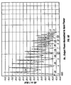
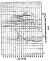
- FIGS 2a and 2b there are shown computer simulated curves of radiated acoustic power and driver exhaustion vs. frequency for a waveguide loudspeaker system of the type shown in Figure 1, (curve 32), without acoustically absorbing material 13 and with a length of 660 mm (26 inches), and for a straight walled undamped waveguide of similar volume and of a length of 914 mm (36 inches) (curve 34).
- the bass range extends to approximately the same frequency (about 70 Hz) and the frequency response for the waveguide system of the type shown in Figure 1 is flatter than the untapered waveguide system.
- Narrowband peaks hereinafter "spikes" in the two curves can be significantly reduced by the use of acoustically absorbing material (13 of Figure 1).
- FIG. 3 there is shown a prior art loudspeaker and waveguide assembly for the purpose of illustrating the present invention.
- An electroacoustical transducer 10 is positioned in one end 40 of an open ended uniform cross-sectional waveguide 14 which has a length y. The ends of the waveguide are in close proximity to each other (i.e. distance t is small).
- transducer 10' radiates a sound wave of a frequency f with wavelength ⁇ which is equal to y, the radiation from the waveguide is of inverse phase to the direct radiation from the transducer, and therefore the radiation from the assembly is significantly reduced at that frequency.
- Electroacoustical transducer 10 is positioned in an end or terminus 12 of an open-ended waveguide 14a.
- Electroacoustical transducer 10 may be a cone and magnet transducer as shown, or some other sort of electroacoustical transducer, such as electrostatic, piezoelectric or other source of sound pressure waves.
- Electroacoustical transducer 10 may face either end of waveguide 14a, or may be mounted in a wall of waveguide 14a and radiate sound waves into waveguide 14a.
- interior walls of waveguide 14a are acoustically low loss.
- waveguide 14a may be a small amount of acoustically absorbing material 13, so that the waveguide is low loss acoustically at low frequencies and has a relatively flat response at higher frequencies.
- the small amount of acoustically absorbing material damps undesirable resonances and provides a smoother output over the range of frequencies radiated by the waveguide but does not prevent the formation of standing waves in the waveguide.
- Second end, or terminus 16, of waveguide 14a radiates sound waves to the surrounding environment. Second end 16 may be flared outwardly for cosmetic or acoustic purposes.
- Waveguide 14a has a plurality of sections 18 1 , 18 2 , ... 18 n along its length.
- Each of the sections 18 1 , 18 2 , .... 18 n has a length x 1 , x 2 , ...x n and a cross-sectional area A 1 , A 2 , ... A n.
- the determination of length of each of the sections will be described below.
- Each of the sections may have a different cross-sectional area than the adjacent section.
- the average cross-sectional area over the length of the waveguide may be determined as disclosed in US 4628528, or may be determined empirically. In this implementation, changes 19 in the cross-sectional area are shown as abrupt. In other implementations the changes in cross-sectional area may be gradual.
- the transducer of FIG. 5a radiates sound of a frequency if with a corresponding wavelength ⁇ which is equal to x, the radiation from the waveguide is of inverse phase to the radiation from the transducer, but the volume velocity, and hence the amplitude, is significantly different. Therefore, even if waveguide 14a is configured such that the ends are in close proximity, as in FIG. 3, the amount of cancellation is significantly reduced.
- the cross section of the waveguide is round, with dimensions A 1 and A 3 being 342 mm 2 (0.3 square inches) and A 2 and A 4 being 709 mm 2 (0.91 square inches).
- FIG. 5b there are shown two computer simulated curves of output acoustic power vs. frequency for a waveguide system with the ends of the waveguide spaced 5 cm apart.
- Curve 42 representing the conventional waveguide as shown in FIG. 3, shows a significant output dip 46 at approximately 350 Hz (hereinafter the cancellation frequency of the waveguide, corresponding to the frequency at which the wavelength is equal to the effective length of the waveguide), and similar dips at integer multiples of the cancellation frequency.
- Dashed curve 44 representing the waveguide system of FIG. 5a, shows that the output dips at about 350 Hz and at the odd multiples of the cancellation frequency have been largely eliminated.
- Each section is of length x/8, where x is the total length of the waveguide.
- FIG. 6b there are shown two computer simulated curves of output acoustic power vs. frequency for a waveguide with the ends of the waveguide spaced 5 cm apart.
- Curve 52 representing a conventional waveguide as shown in FIG. 3, shows a significant output dip 56 at approximately 350Hz, and similar dips at integral multiples of about 350 Hz.
- FIG. 7b there are shown two computer-simulated curves of output acoustic power vs. frequency for a waveguide with the ends of the waveguide spaced 5 cm apart.
- Dashed curve 60 representing the conventional waveguide as shown in FIG. 3, shows a significant output dip 64 at about 350 Hz, and similar dips at integer multiples of about 350 Hz.
- Curve 62 representing the waveguide of FIG. 7a, shows that the output dips at the cancellation frequency, at odd multiples (3, 5, 7 ... ) of the cancellation frequency, and at two times (2, 6, 10, 14 ...) the odd multiples of the cancellation frequency have been significantly reduced.
- Curve 66 representing a conventional waveguide as shown in FIG. 3, shows a significant output dip 70 at about 350 Hz, and similar dips at integer multiples of about 350 Hz.
- Dashed curve 68 representing a waveguide (not shown) according to FIG.
- the waveguides can be superimposed as shown in Figure 7a, to combine the effects of the waveguides.
- Curve 71 representing a conventional waveguide system, shows a significant output dip 74 at about 350 Hz, and similar dips at integer multiples of about 350 Hz.
- Dashed curve 72 representing a waveguide system (not shown) resulting from a superimposition onto the waveguide of FIG. 7a of a waveguide according to FIG.
- the superimposed waveguide begins to approach the waveguide shown in FIG.10.
- the waveguide has two sections of length x/2.
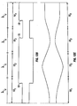
- FIG. 11 shows a parallel sided waveguide with a standing wave 80 formed when sound waves are radiated into the waveguide.
- Standing wave 80 has a tuning frequency if and a corresponding wavelength ⁇ that is equal to the length x of the waveguide.
- Standing wave 80 represents the pressure at points along the length of waveguide.
- Pressure standing wave 80 has pressure nulls 82, 84 at the transducer and at the opening of the waveguide, respectively and another null 86 at a point approximately half way between the transducer and the opening.
- Standing wave 88 formed when sound waves are radiated into the waveguide, represents the volume velocity at points along the length of the waveguide.
- Volume velocity standing wave 88 has volume velocity nulls 92, 94 between pressure nulls 82 and 86 and between pressure nulls 86 and 84, respectively, approximately equidistant from the pressure nulls.
- a waveguide as shown in FIG. 5a (shown in this figure in dotted lines) has four sections, the beginning and the end of the sections is determined by the location of the volume velocity nulls and the pressure nulls of a waveguide with parallel walls and the same average Cross-sectional area.
- First section 181 ends and second section 182 begins at volume velocity null 92; second section 182 ends and third section 183 begins at pressure null 86; third section 183 ends and fourth section 184 begins at volume velocity null 94.
- the distance between the first pressure null and the first volume velocity null, between the first volume velocity null and the second pressure null, between the second pressure null and that second volume velocity null, and between the second volume velocity null and the third pressure null are all equal, so that the lengths X 1 ... X 4 of the sections 18 1 ... 18 4 are all approximately one fourth of the length of the waveguide.
- a standing wave of frequency 2f has five pressure nulls.
- a standing wave of frequency 2f has four volume velocity nulls, between the pressure nulls, and spaced equidistantly between the pressure nulls.
- nf with corresponding wavelengths of ⁇ /4, ⁇ /8,... ⁇ /n have 2n+1 pressure nulls and 2n volume velocity nulls, spaced similarly to the standing wave of frequency 2f and the wavelength of ⁇ /2. Similar standing waves are formed in waveguides the do not have parallel sides, but the location of the nulls may not be evenly spaced. The location of the nulls may be determined empirically.
- FIG. 12a illustrates the principle that adjacent segments having a length equal to the sections of FIG. 11 may have the same cross-sectional area, and still provide the advantages of the invention.
- the lengths of the segments are determined in the same manner as the sections of FIG. 11. Some adjacent sections have the same cross-sectional areas, and at least one of the segments has a larger cross-sectional area than adjacent segments.
- a waveguide system according to Figure 12a has advantages similar to the advantages of a waveguide according to Figure 5a.
- waveguides having segments equal to the distance between a pressure null and a volume velocity null of a standing wave with wavelength ⁇ /2, ⁇ /4, ⁇ /8 ... ⁇ /n with the average cross-sectional areas of the segments conforming to the relationship (( A 2 )( A 4 )...( A n -2 )( A n )) (( A 1 )( A 3 )...( A n -3 )( A n -1 )) 3 and with some adjacent segments having equal average cross-sectional areas, has advantages similar to the waveguide system of FIG. 4.
- FIG. 12b there is illustrated another principle of the invention.
- changes 19 in the cross-sectional area do not occur at the points shown in FIG. 11 and described in the accompanying portion of the disclosure.
- the ratio of the products of the average cross-sectional areas of alternating sections is 3. While a ratio of three provides particularly advantageous results, a waveguide system in which the area ratio is some number greater than one, for example two, shows improved performance.
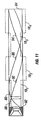
- electroacoustical transducer 10 is positioned in an end of an open-ended waveguide 14.
- electroacoustical transducer 10 is a cone and magnet transducer or some other electroacoustical transducer, such as electrostatic, piezoelectric or other source of acoustic waves.
- Electroacoustical transducer 10 may face either end of waveguide 14', or may be mounted in a wall of waveguide 14' and radiate sound waves into waveguide 14'.
- Cavity 17 in which electroacoustical transducer 10 is positioned closely conforms to electroacoustical transducer 10.
- waveguide 14' Interior walls of waveguide 14' are essentially smooth and acoustically lossless.
- waveguide 14' may be a small amount of acoustically absorbing material 13, so that the waveguide is low loss acoustically.
- the small amount of acoustically absorbing material damps undesirable resonances and provides a smoother output over the range of frequencies radiated by 1. the waveguide system but does not prevent the formation of low frequency standing waves in the waveguide.
- Waveguide 14' has a plurality of sections 18 1 , 18 2 ,... 18 n along its length.
- Each of the sections 18 1 18 2 ,... 18 n has a length x 1 , x 2 , ... x n and a cross-sectional area A 1 , A 2 , ....A n.
- Each of the sections has a cross-sectional area at end closest to the electroacoustical transducer 10 that is larger than the end farthest from the electroacoustical transducer.
- changes 19 in the cross-sectional area are shown as abrupt. In an actual implementation, the changes in cross-sectional area may be gradual.
- a waveguide according to the example of FIG. 13 combines the advantages of the examples of FIGS. 1 and 4.
- the waveguide end cancellation problem is significantly reduced, arid flatter frequency response can be realized with a waveguide system according to FIG. 13 than with a conventional waveguide.
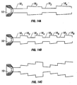
- FIGS. 14a - 14c there are shown waveguide systems similar to the embodiments of FIGS. 7a, 8a, and 9a, but with narrowing cross-sectional areas toward the right. As with the examples of FIGS. 7a, 8a, and 9a end cancellation position problem is significantly reduced; additionally an acoustic performance equivalent to loudspeaker assemblies having longer waveguides can be realized.
- a waveguide as shown in FIGS. 14a - 14c has sections beginning and ending at similar places relative to the pressure nulls and volume velocity nulls, but the nulls may not be evenly placed as in the parallel sided waveguide.
- the location of the nulls may be determined empirically or by computer modeling.
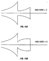
- AR A outlet / A inlet of the unstopped tapered waveguide (i.e. the area ratio)
Landscapes
- Health & Medical Sciences (AREA)
- Otolaryngology (AREA)
- Physics & Mathematics (AREA)
- Engineering & Computer Science (AREA)
- Acoustics & Sound (AREA)
- Signal Processing (AREA)
- Obtaining Desirable Characteristics In Audible-Bandwidth Transducers (AREA)
- Waveguide Aerials (AREA)
Applications Claiming Priority (3)
| Application Number | Priority Date | Filing Date | Title |
|---|---|---|---|
| US146662 | 1993-11-01 | ||
| US09/146,662 US6771787B1 (en) | 1998-09-03 | 1998-09-03 | Waveguide electroacoustical transducing |
| EP99306839A EP0984662B1 (de) | 1998-09-03 | 1999-08-27 | Elektroakustischer Wandler mit Wellenleiter |
Related Parent Applications (2)
| Application Number | Title | Priority Date | Filing Date |
|---|---|---|---|
| EP99306839.4 Division | 1999-08-27 | ||
| EP99306839A Division EP0984662B1 (de) | 1998-09-03 | 1999-08-27 | Elektroakustischer Wandler mit Wellenleiter |
Publications (2)
| Publication Number | Publication Date |
|---|---|
| EP1284585A1 true EP1284585A1 (de) | 2003-02-19 |
| EP1284585B1 EP1284585B1 (de) | 2011-10-05 |
Family
ID=22518408
Family Applications (2)
| Application Number | Title | Priority Date | Filing Date |
|---|---|---|---|
| EP99306839A Expired - Lifetime EP0984662B1 (de) | 1998-09-03 | 1999-08-27 | Elektroakustischer Wandler mit Wellenleiter |
| EP02026327A Expired - Lifetime EP1284585B1 (de) | 1998-09-03 | 1999-08-27 | Elektroakustischer Wellenleiter |
Family Applications Before (1)
| Application Number | Title | Priority Date | Filing Date |
|---|---|---|---|
| EP99306839A Expired - Lifetime EP0984662B1 (de) | 1998-09-03 | 1999-08-27 | Elektroakustischer Wandler mit Wellenleiter |
Country Status (6)
| Country | Link |
|---|---|
| US (3) | US6771787B1 (de) |
| EP (2) | EP0984662B1 (de) |
| JP (1) | JP4417489B2 (de) |
| CN (2) | CN1258185A (de) |
| DE (1) | DE69918502T2 (de) |
| HK (1) | HK1108265A1 (de) |
Families Citing this family (39)
| Publication number | Priority date | Publication date | Assignee | Title |
|---|---|---|---|---|
| US6771787B1 (en) * | 1998-09-03 | 2004-08-03 | Bose Corporation | Waveguide electroacoustical transducing |
| CN100413379C (zh) * | 2000-09-22 | 2008-08-20 | 罗伯特·格伦伯格 | 用在电-声换能器中的相控及压缩插件 |
| US7426280B2 (en) * | 2001-01-02 | 2008-09-16 | Bose Corporation | Electroacoustic waveguide transducing |
| US7254239B2 (en) * | 2001-02-09 | 2007-08-07 | Thx Ltd. | Sound system and method of sound reproduction |
| US7457425B2 (en) * | 2001-02-09 | 2008-11-25 | Thx Ltd. | Vehicle sound system |
| US7433483B2 (en) | 2001-02-09 | 2008-10-07 | Thx Ltd. | Narrow profile speaker configurations and systems |
| FR2824990B1 (fr) * | 2001-05-15 | 2003-09-26 | Jean Pierre Morkerken | Emetteur de son et haut-parleur |
| DE60332371D1 (de) * | 2002-07-12 | 2010-06-10 | Oticon As | Suspensionsmittel für einen wandler |
| DK1550346T3 (da) * | 2002-10-10 | 2009-11-02 | Nokia Corp | Lydfrembringende apparat, mobil elektrisk anordning og system til lydfrembringelse |
| US7676047B2 (en) | 2002-12-03 | 2010-03-09 | Bose Corporation | Electroacoustical transducing with low frequency augmenting devices |
| US7218747B2 (en) * | 2003-12-05 | 2007-05-15 | Nick Huffman | Externally ported loudspeaker enclosure |
| US20070206828A1 (en) * | 2004-04-01 | 2007-09-06 | Koninklijke Philips Electronics, N.V. | Distributed acoustic cabinet |
| US7549509B2 (en) * | 2005-04-21 | 2009-06-23 | Ingersoll-Rand Company | Double throat pulsation dampener for a compressor |
| US20080212807A1 (en) * | 2005-06-08 | 2008-09-04 | General Mems Corporation | Micromachined Acoustic Transducers |
| WO2006135625A2 (en) * | 2005-06-09 | 2006-12-21 | Schultz Roland P | Driver and enclosure combination |
| US7606383B2 (en) * | 2005-10-05 | 2009-10-20 | Qsc Audio Products, Inc. | Curved line array loudspeaker |
| KR20100091185A (ko) | 2007-10-22 | 2010-08-18 | 데이비드 마에시바 | 음향 시스템 |
| US8351629B2 (en) * | 2008-02-21 | 2013-01-08 | Robert Preston Parker | Waveguide electroacoustical transducing |
| US8295526B2 (en) * | 2008-02-21 | 2012-10-23 | Bose Corporation | Low frequency enclosure for video display devices |
| US8615097B2 (en) | 2008-02-21 | 2013-12-24 | Bose Corportion | Waveguide electroacoustical transducing |
| US8351630B2 (en) | 2008-05-02 | 2013-01-08 | Bose Corporation | Passive directional acoustical radiating |
| JP2010093485A (ja) * | 2008-10-07 | 2010-04-22 | Casio Hitachi Mobile Communications Co Ltd | 防水スピーカ、電子機器、及び防水発音機器 |
| US8002078B2 (en) * | 2009-02-19 | 2011-08-23 | Bose Corporation | Acoustic waveguide vibration damping |
| WO2011031794A2 (en) * | 2009-09-08 | 2011-03-17 | Clements Philip R | Inverse horn loudspeakers |
| US8401216B2 (en) * | 2009-10-27 | 2013-03-19 | Saab Sensis Corporation | Acoustic traveling wave tube system and method for forming and propagating acoustic waves |
| US8265310B2 (en) * | 2010-03-03 | 2012-09-11 | Bose Corporation | Multi-element directional acoustic arrays |
| US8553894B2 (en) | 2010-08-12 | 2013-10-08 | Bose Corporation | Active and passive directional acoustic radiating |
| CN102883252A (zh) * | 2011-07-14 | 2013-01-16 | 上海一诺仪表有限公司 | 超声波换能器锥体形超波导振动子 |
| US9204211B2 (en) | 2011-12-16 | 2015-12-01 | Avnera Corporation | Pad-type device case providing enhanced audio functionality and output |
| US9173018B2 (en) | 2012-06-27 | 2015-10-27 | Bose Corporation | Acoustic filter |
| EP2974356B1 (de) | 2013-03-13 | 2020-05-06 | THX Ltd | Flacher lautsprecher |
| US9754578B2 (en) | 2014-01-09 | 2017-09-05 | Dolby Laboratories Licensing Corporation | Loudspeaker horn and cabinet |
| US10057701B2 (en) | 2015-03-31 | 2018-08-21 | Bose Corporation | Method of manufacturing a loudspeaker |
| US9451355B1 (en) | 2015-03-31 | 2016-09-20 | Bose Corporation | Directional acoustic device |
| JP2019515590A (ja) * | 2016-05-10 | 2019-06-06 | ボーズ・コーポレーションBose Corporation | 音響装置 |
| US9749735B1 (en) * | 2016-07-06 | 2017-08-29 | Bose Corporation | Waveguide |
| DE102017214404B4 (de) * | 2017-08-18 | 2023-12-28 | Audi Ag | Lautsprecheranordnung und Fahrzeug |
| WO2019107781A1 (en) | 2017-11-28 | 2019-06-06 | Samsung Electronics Co., Ltd. | Loudspeaker and sound outputting apparatus having the same |
| GB2590656A (en) | 2019-12-23 | 2021-07-07 | Gp Acoustics International Ltd | Loudspeakers |
Citations (5)
| Publication number | Priority date | Publication date | Assignee | Title |
|---|---|---|---|---|
| FR1359616A (fr) * | 1960-07-05 | 1964-04-30 | Csf | Nouveau projecteur d'ondes acoustiques |
| FR2653630A1 (fr) * | 1989-10-23 | 1991-04-26 | Scotto Di Carlo Gilles | Structure d'enceinte acoustique. |
| US5373564A (en) * | 1992-10-02 | 1994-12-13 | Spear; Robert J. | Transmission line for planar waves |
| WO1996011558A1 (en) * | 1994-10-10 | 1996-04-18 | A/S Brüel & Kjær | Omnidirectional sound source |
| WO1998020659A1 (en) * | 1996-11-07 | 1998-05-14 | Ericsson, Inc. | Radiotelephone having an acoustical wave guide coupled to a speaker |
Family Cites Families (37)
| Publication number | Priority date | Publication date | Assignee | Title |
|---|---|---|---|---|
| US1755636A (en) * | 1927-09-22 | 1930-04-22 | Radio Patents Corp | Loud-speaker |
| US2293181A (en) * | 1940-07-17 | 1942-08-18 | Int Standard Electric Corp | Sound absorbing apparatus |
| US3486578A (en) * | 1967-12-21 | 1969-12-30 | Lawrence Albarino | Electro-mechanical reproduction of sound |
| SE358800B (de) * | 1972-02-29 | 1973-08-06 | Bostedt J | |
| US3940576A (en) * | 1974-03-19 | 1976-02-24 | Schultz Herbert J | Loudspeaker having sound funnelling element |
| US4340778A (en) | 1979-11-13 | 1982-07-20 | Bennett Sound Corporation | Speaker distortion compensator |
| US4628528A (en) * | 1982-09-29 | 1986-12-09 | Bose Corporation | Pressure wave transducing |
| US4930596A (en) * | 1987-06-16 | 1990-06-05 | Matsushita Electric Industrial Co., Ltd. | Loudspeaker system |
| US5012890A (en) * | 1988-03-23 | 1991-05-07 | Yamaha Corporation | Acoustic apparatus |
| EP0477256B1 (de) * | 1989-06-12 | 1993-08-25 | Josef Gail | Kolbenmaschine |
| US5105905A (en) * | 1990-05-07 | 1992-04-21 | Rice Winston C | Co-linear loudspeaker system |
| US5740259A (en) * | 1992-06-04 | 1998-04-14 | Bose Corporation | Pressure wave transducing |
| US6002781A (en) * | 1993-02-24 | 1999-12-14 | Matsushita Electric Industrial Co., Ltd. | Speaker system |
| US6278789B1 (en) * | 1993-05-06 | 2001-08-21 | Bose Corporation | Frequency selective acoustic waveguide damping |
| AU666616B2 (en) * | 1993-06-30 | 1996-02-15 | Sanyo Electric Co., Ltd. | Microwave oven including antenna for radiating microwave |
| US5481385A (en) * | 1993-07-01 | 1996-01-02 | Alliedsignal Inc. | Direct view display device with array of tapered waveguide on viewer side |
| GB2295518B (en) * | 1994-12-23 | 1998-08-05 | Graeme John Huon | Loudspeaker system incorporating acoustic waveguide filters and method of construction |
| US5673329A (en) * | 1995-03-23 | 1997-09-30 | Wiener; David | Omni-directional loudspeaker system |
| US5644109A (en) * | 1995-05-30 | 1997-07-01 | Newman; Ottis G. | Speaker enclosure |
| US5821471A (en) | 1995-11-30 | 1998-10-13 | Mcculler; Mark A. | Acoustic system |
| US5828759A (en) | 1995-11-30 | 1998-10-27 | Siemens Electric Limited | System and method for reducing engine noise |
| US5832099A (en) * | 1997-01-08 | 1998-11-03 | Wiener; David | Speaker system having an undulating rigid speaker enclosure |
| US5815589A (en) * | 1997-02-18 | 1998-09-29 | Wainwright; Charles E. | Push-pull transmission line loudspeaker |
| JPH11220789A (ja) | 1998-01-30 | 1999-08-10 | Sony Corp | 電気音響変換装置 |
| US6144751A (en) * | 1998-02-24 | 2000-11-07 | Velandia; Erich M. | Concentrically aligned speaker enclosure |
| US6771787B1 (en) * | 1998-09-03 | 2004-08-03 | Bose Corporation | Waveguide electroacoustical transducing |
| DE19861018C2 (de) * | 1998-12-15 | 2001-06-13 | Fraunhofer Ges Forschung | Gesteuerter akustischer Wellenleiter zur Schalldämpfung |
| US6374120B1 (en) * | 1999-02-16 | 2002-04-16 | Denso Corporation | Acoustic guide for audio transducers |
| US6704425B1 (en) * | 1999-11-19 | 2004-03-09 | Virtual Bass Technologies, Llc | System and method to enhance reproduction of sub-bass frequencies |
| US6431309B1 (en) * | 2000-04-14 | 2002-08-13 | C. Ronald Coffin | Loudspeaker system |
| JP4240795B2 (ja) * | 2000-10-10 | 2009-03-18 | コニカミノルタビジネステクノロジーズ株式会社 | 画像形成システム及び画像形成装置並びにジョブデータの処理方法 |
| US7426280B2 (en) * | 2001-01-02 | 2008-09-16 | Bose Corporation | Electroacoustic waveguide transducing |
| US6662627B2 (en) * | 2001-06-22 | 2003-12-16 | Desert Research Institute | Photoacoustic instrument for measuring particles in a gas |
| US6820431B2 (en) * | 2002-10-31 | 2004-11-23 | General Electric Company | Acoustic impedance-matched fuel nozzle device and tunable fuel injection resonator assembly |
| US6792907B1 (en) * | 2003-03-04 | 2004-09-21 | Visteon Global Technologies, Inc. | Helmholtz resonator |
| JP2006125381A (ja) * | 2004-09-29 | 2006-05-18 | Toyoda Gosei Co Ltd | 共鳴器 |
| DE102007039598B4 (de) * | 2006-09-05 | 2010-07-22 | DENSO CORPORATION, Kariya-shi | Ultraschallsensor und Hindernis-Detektorvorrichtung |
-
1998
- 1998-09-03 US US09/146,662 patent/US6771787B1/en not_active Expired - Lifetime
-
1999
- 1999-08-27 EP EP99306839A patent/EP0984662B1/de not_active Expired - Lifetime
- 1999-08-27 DE DE1999618502 patent/DE69918502T2/de not_active Expired - Lifetime
- 1999-08-27 EP EP02026327A patent/EP1284585B1/de not_active Expired - Lifetime
- 1999-09-03 JP JP25030999A patent/JP4417489B2/ja not_active Expired - Lifetime
- 1999-09-03 CN CN99118610A patent/CN1258185A/zh active Pending
- 1999-09-03 CN CN200710089694.0A patent/CN101026895B/zh not_active Expired - Lifetime
-
2000
- 2000-12-28 HK HK08102029.3A patent/HK1108265A1/xx not_active IP Right Cessation
-
2004
- 2004-06-11 US US10/866,566 patent/US7623670B2/en not_active Expired - Lifetime
-
2009
- 2009-10-09 US US12/576,274 patent/US20100092019A1/en not_active Abandoned
Patent Citations (5)
| Publication number | Priority date | Publication date | Assignee | Title |
|---|---|---|---|---|
| FR1359616A (fr) * | 1960-07-05 | 1964-04-30 | Csf | Nouveau projecteur d'ondes acoustiques |
| FR2653630A1 (fr) * | 1989-10-23 | 1991-04-26 | Scotto Di Carlo Gilles | Structure d'enceinte acoustique. |
| US5373564A (en) * | 1992-10-02 | 1994-12-13 | Spear; Robert J. | Transmission line for planar waves |
| WO1996011558A1 (en) * | 1994-10-10 | 1996-04-18 | A/S Brüel & Kjær | Omnidirectional sound source |
| WO1998020659A1 (en) * | 1996-11-07 | 1998-05-14 | Ericsson, Inc. | Radiotelephone having an acoustical wave guide coupled to a speaker |
Also Published As
| Publication number | Publication date |
|---|---|
| CN1258185A (zh) | 2000-06-28 |
| DE69918502D1 (de) | 2004-08-12 |
| US20050036642A1 (en) | 2005-02-17 |
| EP0984662B1 (de) | 2004-07-07 |
| CN101026895A (zh) | 2007-08-29 |
| US20100092019A1 (en) | 2010-04-15 |
| DE69918502T2 (de) | 2004-11-18 |
| JP4417489B2 (ja) | 2010-02-17 |
| CN101026895B (zh) | 2014-01-29 |
| JP2000092583A (ja) | 2000-03-31 |
| EP0984662A3 (de) | 2001-04-11 |
| HK1108265A1 (en) | 2008-05-02 |
| US7623670B2 (en) | 2009-11-24 |
| US6771787B1 (en) | 2004-08-03 |
| EP1284585B1 (de) | 2011-10-05 |
| EP0984662A2 (de) | 2000-03-08 |
Similar Documents
| Publication | Publication Date | Title |
|---|---|---|
| EP1284585A1 (de) | Elektroakustische Wellenleiterwandlung | |
| US8175311B2 (en) | Electroacoustic waveguide transducing | |
| EP1178702B1 (de) | Wellenformungsschallgehäuse | |
| CN107293283B (zh) | 一种声学超表面和声波聚焦装置 | |
| US8351629B2 (en) | Waveguide electroacoustical transducing | |
| US6094495A (en) | Horn-type loudspeaker system | |
| EP1110426B1 (de) | Plattenförmige akustistische vorrichtung unter verwendung von biegewellenmoden | |
| US20060285712A1 (en) | Coaxial mid-frequency and high-frequency loudspeaker | |
| CN101467466B (zh) | 相位塞 | |
| US4629029A (en) | Multiple driver manifold | |
| JPH05268690A (ja) | 広角度の指向性を有するスピーカ装置 | |
| US8615097B2 (en) | Waveguide electroacoustical transducing | |
| US7093688B2 (en) | Structure for preventing the generation of standing waves and a method for implementing the same | |
| KR20010083946A (ko) | 비상관성 상(Phase) 발산 음향원을 구비한 확성기 | |
| US11647326B2 (en) | Loudspeakers | |
| JP3267999B2 (ja) | スピーカシステム | |
| US2805728A (en) | Sound dispersion device with internal divergent acoustical lens | |
| JPH01279698A (ja) | スピーカシステム | |
| JPH03192898A (ja) | スピーカシステム |
Legal Events
| Date | Code | Title | Description |
|---|---|---|---|
| PUAI | Public reference made under article 153(3) epc to a published international application that has entered the european phase |
Free format text: ORIGINAL CODE: 0009012 |
|
| AC | Divisional application: reference to earlier application |
Ref document number: 0984662 Country of ref document: EP Kind code of ref document: P |
|
| AK | Designated contracting states |
Designated state(s): AT BE BG CH CY CZ DE DK EE ES FI FR GB GR IE IT LI LU MC NL PT SE SK TR |
|
| AX | Request for extension of the european patent |
Extension state: AL LT LV MK RO SI |
|
| 17P | Request for examination filed |
Effective date: 20030814 |
|
| AKX | Designation fees paid |
Designated state(s): DE FR |
|
| 17Q | First examination report despatched |
Effective date: 20070831 |
|
| GRAP | Despatch of communication of intention to grant a patent |
Free format text: ORIGINAL CODE: EPIDOSNIGR1 |
|
| RTI1 | Title (correction) |
Free format text: ELECTROACOUSTIC WAVEGUIDE |
|
| GRAS | Grant fee paid |
Free format text: ORIGINAL CODE: EPIDOSNIGR3 |
|
| GRAA | (expected) grant |
Free format text: ORIGINAL CODE: 0009210 |
|
| AC | Divisional application: reference to earlier application |
Ref document number: 0984662 Country of ref document: EP Kind code of ref document: P |
|
| AK | Designated contracting states |
Kind code of ref document: B1 Designated state(s): DE FR |
|
| REG | Reference to a national code |
Ref country code: DE Ref legal event code: R096 Ref document number: 69943769 Country of ref document: DE Effective date: 20111201 |
|
| PLBE | No opposition filed within time limit |
Free format text: ORIGINAL CODE: 0009261 |
|
| STAA | Information on the status of an ep patent application or granted ep patent |
Free format text: STATUS: NO OPPOSITION FILED WITHIN TIME LIMIT |
|
| 26N | No opposition filed |
Effective date: 20120706 |
|
| REG | Reference to a national code |
Ref country code: DE Ref legal event code: R097 Ref document number: 69943769 Country of ref document: DE Effective date: 20120706 |
|
| REG | Reference to a national code |
Ref country code: FR Ref legal event code: PLFP Year of fee payment: 18 |
|
| REG | Reference to a national code |
Ref country code: FR Ref legal event code: PLFP Year of fee payment: 19 |
|
| REG | Reference to a national code |
Ref country code: FR Ref legal event code: PLFP Year of fee payment: 20 |
|
| PGFP | Annual fee paid to national office [announced via postgrant information from national office to epo] |
Ref country code: DE Payment date: 20180829 Year of fee payment: 20 Ref country code: FR Payment date: 20180827 Year of fee payment: 20 |
|
| REG | Reference to a national code |
Ref country code: DE Ref legal event code: R071 Ref document number: 69943769 Country of ref document: DE |