EP1284177A1 - Vorrichtung zum Halten eines Energie zuführenden Kabelbündels an einem Schweissroboter - Google Patents
Vorrichtung zum Halten eines Energie zuführenden Kabelbündels an einem Schweissroboter Download PDFInfo
- Publication number
- EP1284177A1 EP1284177A1 EP02291983A EP02291983A EP1284177A1 EP 1284177 A1 EP1284177 A1 EP 1284177A1 EP 02291983 A EP02291983 A EP 02291983A EP 02291983 A EP02291983 A EP 02291983A EP 1284177 A1 EP1284177 A1 EP 1284177A1
- Authority
- EP
- European Patent Office
- Prior art keywords
- shaft
- bundle
- deflection arm
- movable part
- elements
- Prior art date
- Legal status (The legal status is an assumption and is not a legal conclusion. Google has not performed a legal analysis and makes no representation as to the accuracy of the status listed.)
- Granted
Links
Images
Classifications
-
- B—PERFORMING OPERATIONS; TRANSPORTING
- B25—HAND TOOLS; PORTABLE POWER-DRIVEN TOOLS; MANIPULATORS
- B25J—MANIPULATORS; CHAMBERS PROVIDED WITH MANIPULATION DEVICES
- B25J19/00—Accessories fitted to manipulators, e.g. for monitoring, for viewing; Safety devices combined with or specially adapted for use in connection with manipulators
- B25J19/0025—Means for supplying energy to the end effector
Definitions
- the invention relates to a beam element holding device for transporting energy for a machine comprising moving parts powered by these elements.
- the invention also relates to an application of such a device to a welding robot, and more particularly to a welding robot for the automotive industry, which is the preferred application of the invention.
- the term "automaton” covers many devices: robots themselves, control connected to other devices by the above-mentioned harness elements, etc., generally any device comprising a mobile powered part by the aforementioned beam.
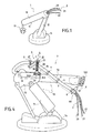
- FIG. 1 appended to this description illustrates very schematically an example a welding robot 1 according to the known art provided of a bundle of electric current supply cable.
- the welding robot usually includes a chassis fixed to the ground or on a fixed support 14. It also includes an articulated arm 10, constituted in FIG. 1 of two members 11 and 12, and, at the free end of member 11, a welding member 13 with clamps. Naturally, organs of motorization (not represented) putting relative movement the various elements of the arm and controlling the welding pliers 13. It is thus possible to obtain several degrees of freedom of movement. The number of degrees of freedom depends on the type of robot used and suitable for the specific application envisaged.
- the bundle also includes flexible lines for fluid transport.
- the limbs, 11 and 12, of arm 10 are animated by rapid relative movements and repeated during welding processes. It follows that the cables, 20 to 22, of the beam 2 are also constantly stressed and under stress high: tensile and torsional forces.
- cables, 20 to 22, of the bundle 2 are only maintained by their base, entry points into the robot arm 1.
- the invention aims to overcome the drawbacks of the devices of the art known, and some of which have just been recalled.
- the invention sets itself the goal of a device for holding elements of energy transport bundle for a machine comprising moving parts powered by these elements meeting the needs that have just been evoked
- the elements mentioned above flexible cables or conduits, are supported by a deflection arm, movable in rotation around a shaft subject to a movable part of the automaton by a first fixing member.
- the shaft is coaxial with a spring, of the type sausage or the like, one end of which is integral with the fixing member, the other being integral with the deflection arm and exerts a restoring force when this deviates from a position that will be called initial or rest.
- the elements of the bundle are also threaded in a sheath, preferably made of flexible plastic.
- the sheath accompanies the beam over a determined length.
- the end of the sheath by which are introduced the elements of the beam is itself subject to the automaton by a second fixing member.
- This arrangement allows effective maintenance and guidance of the beam element in the exit area.
- the main object of the invention is therefore a holding device elements of the energy supply bundle of a PLC comprising at at least one movable part connected to said beam, characterized in that it comprises at least one so-called deflection arm, supporting at least one element of said beam, in that a first end of said deflection arm is movable in rotation around a first end of a tree, along a first axis, in that said shaft is subject, at a second end, to a first member of fixed attachment to said movable part, in that said shaft is associated with spring means exerting on said deflection arm a restoring force towards a determined position in space, called rest, relative to said tree, of so as to maintain and guide said element during displacements in the space of said movable part.
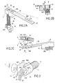
- FIGS. 2A to 4 a exemplary embodiment of a device 3 for holding beam elements, in the occurrence of electric power supply cable, according to a mode of preferred embodiment of the invention, and an example of a robot 7 provided with such a device 3.
- FIG. 2A illustrates the device 3 in perspective.
- the device 3 comprises an arm support 30, which will be called reference.
- it is made up by a rectangular parallelepipedic member 30 secured at one end to a block 31, also substantially rectangular parallelepiped.
- the fixation is carried out by any appropriate means, screw or other, under the single reference 301.
- the block 31 is drilled right through, cavity 310, so as to accommodate a shaft 32, of axis of symmetry ⁇ orthogonal to the plane formed by the support arm 30.
- a ball bearing 36 is advantageously provided housed in the cavity 310 or any similar function.
- the shaft 32 is associated with spring means 35, advantageously of the flange type.
- the shaft 32 is coaxial with the spring 35.
- the shaft 32 and the spring 35 are subject at their ends, which one will say arbitrarily inferior, to a fixing member 34, the spring being further fixed by a clip or any other member 33.
- the fixing member 34 is itself subject to the automaton, as it will be shown with reference to FIG. 4, by any appropriate means, screw or other, 340 and 341.
- Figure 2B is a detail figure showing the device in section partial, so as to highlight the cooperation of the rotation shaft 32, of the corresponding end of the spring 35 and of the block 31 to which the arm is fixed of reference 30.
- the end of the spring 35 extends into the block 31 with a finger 350
- the beam 2 is secured to the deflection arm 30.
- the subjection to the deflection arm 30 is not not rigid.
- FIG. 2C more particularly illustrates an example of preferred embodiment of means 5 for attaching the bundle 2 to the deflection arm 30.
- the deflection arm 30 is advantageously provided with a certain number holes distributed along its longitudinal axis ⁇ '. These holes allow fix on its wall, which will be called upper, in an adjustable way, a plate 50 supporting the so-called lower end of a rotation shaft 51 of which the so-called upper end supports itself, free rotation, a ring of beam fixing 53.
- it is composed of two half-shells, 530 and 531, which can be opened, so as to introduce the beam 2.
- a locking / unlocking member 532 so as to join the two half-shells, 530 and 531, when the harness 2 is inserted between them.
- It may be a loop member 532, of the lever type, or any other appropriate body.
- the fixing ring 50 can move in rotation about the axis of symmetry ⁇ "of the shaft 51.
- the cables making up the bundle 2 are not threaded naked in the fastening means 5. They are threaded beforehand in a flexible sheath 4, for example plastic, of the "accordion" type. This sheath 4 accompanies the cables of bundle 2 over a determined length l, at from the arm of the automaton 7, as will be shown later by more specific reference to Figure 4.
- the fixing member 6 comprises a ring 60, preferably double: two receptacles, 600 and 601 joined by a locking / unlocking 602, for example by screw.
- This ring 60 traps an organ, which will be called "nut” 63, pierced right through by channels, 630 to 632 in the example described. We thread into the channels, 630 to 632, the different cables, 20 to 22, of bundle 2.
- the material constituting the "nut” 63 is a flexible material, for example plastic, so as to maintain the cables, 20 to 22, without injuring them.
- the ring 60 comprises means of attachment 61 to a zone PLC controller 7.
- FIG. 4 Reference has been made in FIG. 4 that the components necessary for the good understanding of the invention, the automaton per se being of a type any, in particular in accordance with known art.
- the automaton 7 consists more particularly in a device called a manipulator.
- the complete system further includes a control device (not shown) from which the cables making up the harness 2.
- the manipulator 7 comprises an articulated arm 70 comprising two series of interconnected members, 71 and 72.
- the free end of arm 72 is fitted with a tool holder 720 intended, for example, to receive pliers welding (not shown).
- the assembly rests on a fixed frame 74.
- the bundle 2 in its sheath 4 enters the arm 70 by the end of arm 72 near an area of articulation 721 between the two members, 71 and 72.
- the device 3 is arranged in the upper part of the manipulator 7, in an area of the member 72 close to the joint 721.
- the device 3 When, in particular, the member 72 moves in space, the device 3 accompanies these movements and effectively guides and supports the bundle 2 in its sheath 4, one end of the latter being trapped in the member 72.
- the other end in a preferred embodiment is subject, thanks to the means of attachment 6, to the automaton, advantageously at the end of the member 72.
- the exact position of the device 3 (and of its axis of rotation ⁇ ) and the length of the deflection arm 30 are determined according to various parameters which depend on the envisaged application, in particular dimensions of the components of the arm 70 and the degree of rotation to be obtained, so that whatever the relative positions of the two sets of members 71 and 72, the desired beam support and guidance are obtained.
- the stiffness of the spring is determined according to the parameters geometric and other associated with beam 2 (own stiffness of the beam, its mass, etc.).
- the device according to the invention can find application for any automaton comprising moving parts supplied by elements of energy supply beam, both electric and fluid, as it was recalled.
Applications Claiming Priority (2)
| Application Number | Priority Date | Filing Date | Title |
|---|---|---|---|
| FR0110804A FR2828655B1 (fr) | 2001-08-14 | 2001-08-14 | Dispositif de maintien d'elements de faisceau de transport d'energie a un automate et son application a un robot de soudage |
| FR0110804 | 2001-08-14 |
Publications (2)
| Publication Number | Publication Date |
|---|---|
| EP1284177A1 true EP1284177A1 (de) | 2003-02-19 |
| EP1284177B1 EP1284177B1 (de) | 2006-11-15 |
Family
ID=8866522
Family Applications (1)
| Application Number | Title | Priority Date | Filing Date |
|---|---|---|---|
| EP02291983A Expired - Lifetime EP1284177B1 (de) | 2001-08-14 | 2002-08-07 | Vorrichtung zum Halten eines Energie zuführenden Kabelbündels an einem Schweissroboter |
Country Status (4)
| Country | Link |
|---|---|
| EP (1) | EP1284177B1 (de) |
| AT (1) | ATE345200T1 (de) |
| DE (1) | DE60216019D1 (de) |
| FR (1) | FR2828655B1 (de) |
Cited By (1)
| Publication number | Priority date | Publication date | Assignee | Title |
|---|---|---|---|---|
| DE102021127283A1 (de) | 2021-10-21 | 2023-04-27 | Murrplastik Systemtechnik Gmbh | Vorrichtung zur Führung von Leitungen |
Families Citing this family (1)
| Publication number | Priority date | Publication date | Assignee | Title |
|---|---|---|---|---|
| DE102022123623A1 (de) * | 2022-09-15 | 2024-03-21 | Dürr Systems Ag | Rückstellvorrichtung zum Rückstellen zumindest einer Leitung |
Citations (5)
| Publication number | Priority date | Publication date | Assignee | Title |
|---|---|---|---|---|
| US4705243A (en) * | 1983-10-19 | 1987-11-10 | Kuka Schweissanlangen | System of externally holding and guiding supply lines to moving implements of manipulators |
| DE9217659U1 (de) * | 1992-12-24 | 1994-04-07 | Kuka Schweissanlagen & Roboter | Leitungsführung für eine Versorgungsleitung an einem mehrachsigen Roboter |
| FR2724866A1 (fr) * | 1994-09-27 | 1996-03-29 | Caty Polymeres Sa | Accastillage universel pour robot industriel |
| DE20010696U1 (de) * | 2000-06-15 | 2001-07-26 | Kuka Roboter Gmbh | Vorrichtung zum Festlegen von Kabeln eines Kabelführungsschlauchs |
| US20020007692A1 (en) * | 2000-07-14 | 2002-01-24 | Torbjorn Albertsson | Manipulator |
-
2001
- 2001-08-14 FR FR0110804A patent/FR2828655B1/fr not_active Expired - Fee Related
-
2002
- 2002-08-07 DE DE60216019T patent/DE60216019D1/de not_active Expired - Lifetime
- 2002-08-07 EP EP02291983A patent/EP1284177B1/de not_active Expired - Lifetime
- 2002-08-07 AT AT02291983T patent/ATE345200T1/de not_active IP Right Cessation
Patent Citations (5)
| Publication number | Priority date | Publication date | Assignee | Title |
|---|---|---|---|---|
| US4705243A (en) * | 1983-10-19 | 1987-11-10 | Kuka Schweissanlangen | System of externally holding and guiding supply lines to moving implements of manipulators |
| DE9217659U1 (de) * | 1992-12-24 | 1994-04-07 | Kuka Schweissanlagen & Roboter | Leitungsführung für eine Versorgungsleitung an einem mehrachsigen Roboter |
| FR2724866A1 (fr) * | 1994-09-27 | 1996-03-29 | Caty Polymeres Sa | Accastillage universel pour robot industriel |
| DE20010696U1 (de) * | 2000-06-15 | 2001-07-26 | Kuka Roboter Gmbh | Vorrichtung zum Festlegen von Kabeln eines Kabelführungsschlauchs |
| US20020007692A1 (en) * | 2000-07-14 | 2002-01-24 | Torbjorn Albertsson | Manipulator |
Cited By (1)
| Publication number | Priority date | Publication date | Assignee | Title |
|---|---|---|---|---|
| DE102021127283A1 (de) | 2021-10-21 | 2023-04-27 | Murrplastik Systemtechnik Gmbh | Vorrichtung zur Führung von Leitungen |
Also Published As
| Publication number | Publication date |
|---|---|
| FR2828655B1 (fr) | 2003-11-07 |
| ATE345200T1 (de) | 2006-12-15 |
| EP1284177B1 (de) | 2006-11-15 |
| FR2828655A1 (fr) | 2003-02-21 |
| DE60216019D1 (de) | 2006-12-28 |
Similar Documents
| Publication | Publication Date | Title |
|---|---|---|
| EP2476502B1 (de) | Zange mit einem versetzten Ausgleichsmodul zum Einspannen von Blechen, die zusammen mit einem Greifarm und verwendet wird | |
| BE898154A (fr) | Manipuleur pour positionner des pièces à usiner ou d'autres charges. | |
| EP0388293A1 (de) | Treibriemenspanner | |
| FR2671752A1 (fr) | Systeme actionneur de pinces pour un cadre de fixation supporte par un convoyeur. | |
| CA1292030C (fr) | Dispositif de stockage d'energie mecanique a force d'accrochage nulle | |
| EP1284177B1 (de) | Vorrichtung zum Halten eines Energie zuführenden Kabelbündels an einem Schweissroboter | |
| FR2491380A1 (fr) | Robot manipulateur, notamment pour le positionnement automatique de pieces a usiner | |
| FR2670424A1 (fr) | Dispositif manipulateur pour deplacer un objet, dans l'espace, parallelement a lui-meme. | |
| EP1304195A1 (de) | Haltevorrichtung für einen zu einem Automaten Energie zuleitende Kabelbaum und ihre Anwendung für einen Schweissroboter | |
| FR2574334A1 (fr) | Systeme de manipulation de pieces de montage | |
| EP0109405B1 (de) | Einrichtung zum greifen von gegenständen für manipulator vom robotertyp | |
| FR3001177A1 (fr) | Dispositif telescopique de guidage et de rappel | |
| FR2564023A1 (fr) | Pince porte-outil | |
| EP1072366A1 (de) | Fördereinrichtung | |
| FR2604138A1 (fr) | Dispositif de maintien en ligne au droit d'un pylone de cables aeriens entraines a defilement, et installation de transport a cables aeriens comportant un tel dispositif | |
| EP3546141A1 (de) | Vorrichtung mit kabeln für die anwendung von gleichen kräften an mindestens zwei von einander entfernten punkten | |
| FR2713728A1 (fr) | Dispositif de serrage rapide d'éléments mobiles dans un habitacle de véhicules. | |
| EP0190062B1 (de) | Einstellbarer Träger für einen Richtspiegel eines Scheinwerfers | |
| FR2602170A1 (fr) | Main mecanique pour la manipulation d'objets | |
| FR2581914A1 (fr) | Dispositif de prehension de pieces pour robot manipulateur | |
| FR2610562A1 (fr) | Pince d'intervention articulee a cinq degres de liberte | |
| FR2662314A1 (fr) | Poignet pour le maintien de cables. | |
| FR2569638A1 (fr) | Retroviseur pour vehicule comportant des moyens d'articulation particuliers | |
| FR2692514A1 (fr) | Dispositif formant interface mécanique souple interposée entre le poignet d'un robot et un outil de travail de celui-ci. | |
| FR2678193A1 (fr) | Robot de soudage par faisceau laser. |
Legal Events
| Date | Code | Title | Description |
|---|---|---|---|
| PUAI | Public reference made under article 153(3) epc to a published international application that has entered the european phase |
Free format text: ORIGINAL CODE: 0009012 |
|
| AK | Designated contracting states |
Designated state(s): AT BE BG CH CY CZ DE DK EE ES FI FR GB GR IE IT LI LU MC NL PT SE SK TR |
|
| AX | Request for extension of the european patent |
Extension state: AL LT LV MK RO SI |
|
| 17P | Request for examination filed |
Effective date: 20030527 |
|
| AKX | Designation fees paid |
Designated state(s): AT BE BG CH CY CZ DE DK EE ES FI FR GB GR IE IT LI LU MC NL PT SE SK TR |
|
| GRAP | Despatch of communication of intention to grant a patent |
Free format text: ORIGINAL CODE: EPIDOSNIGR1 |
|
| GRAS | Grant fee paid |
Free format text: ORIGINAL CODE: EPIDOSNIGR3 |
|
| GRAA | (expected) grant |
Free format text: ORIGINAL CODE: 0009210 |
|
| AK | Designated contracting states |
Kind code of ref document: B1 Designated state(s): AT BE BG CH CY CZ DE DK EE ES FI FR GB GR IE IT LI LU MC NL PT SE SK TR |
|
| PG25 | Lapsed in a contracting state [announced via postgrant information from national office to epo] |
Ref country code: IT Free format text: LAPSE BECAUSE OF FAILURE TO SUBMIT A TRANSLATION OF THE DESCRIPTION OR TO PAY THE FEE WITHIN THE PRESCRIBED TIME-LIMIT;WARNING: LAPSES OF ITALIAN PATENTS WITH EFFECTIVE DATE BEFORE 2007 MAY HAVE OCCURRED AT ANY TIME BEFORE 2007. THE CORRECT EFFECTIVE DATE MAY BE DIFFERENT FROM THE ONE RECORDED. Effective date: 20061115 Ref country code: FI Free format text: LAPSE BECAUSE OF FAILURE TO SUBMIT A TRANSLATION OF THE DESCRIPTION OR TO PAY THE FEE WITHIN THE PRESCRIBED TIME-LIMIT Effective date: 20061115 Ref country code: SK Free format text: LAPSE BECAUSE OF FAILURE TO SUBMIT A TRANSLATION OF THE DESCRIPTION OR TO PAY THE FEE WITHIN THE PRESCRIBED TIME-LIMIT Effective date: 20061115 Ref country code: NL Free format text: LAPSE BECAUSE OF FAILURE TO SUBMIT A TRANSLATION OF THE DESCRIPTION OR TO PAY THE FEE WITHIN THE PRESCRIBED TIME-LIMIT Effective date: 20061115 Ref country code: CZ Free format text: LAPSE BECAUSE OF FAILURE TO SUBMIT A TRANSLATION OF THE DESCRIPTION OR TO PAY THE FEE WITHIN THE PRESCRIBED TIME-LIMIT Effective date: 20061115 Ref country code: AT Free format text: LAPSE BECAUSE OF FAILURE TO SUBMIT A TRANSLATION OF THE DESCRIPTION OR TO PAY THE FEE WITHIN THE PRESCRIBED TIME-LIMIT Effective date: 20061115 Ref country code: IE Free format text: LAPSE BECAUSE OF FAILURE TO SUBMIT A TRANSLATION OF THE DESCRIPTION OR TO PAY THE FEE WITHIN THE PRESCRIBED TIME-LIMIT Effective date: 20061115 |
|
| REG | Reference to a national code |
Ref country code: GB Ref legal event code: FG4D Free format text: NOT ENGLISH |
|
| REG | Reference to a national code |
Ref country code: CH Ref legal event code: EP |
|
| REF | Corresponds to: |
Ref document number: 60216019 Country of ref document: DE Date of ref document: 20061228 Kind code of ref document: P |
|
| REG | Reference to a national code |
Ref country code: IE Ref legal event code: FG4D Free format text: LANGUAGE OF EP DOCUMENT: FRENCH |
|
| PG25 | Lapsed in a contracting state [announced via postgrant information from national office to epo] |
Ref country code: BG Free format text: LAPSE BECAUSE OF FAILURE TO SUBMIT A TRANSLATION OF THE DESCRIPTION OR TO PAY THE FEE WITHIN THE PRESCRIBED TIME-LIMIT Effective date: 20070215 Ref country code: DK Free format text: LAPSE BECAUSE OF FAILURE TO SUBMIT A TRANSLATION OF THE DESCRIPTION OR TO PAY THE FEE WITHIN THE PRESCRIBED TIME-LIMIT Effective date: 20070215 Ref country code: SE Free format text: LAPSE BECAUSE OF FAILURE TO SUBMIT A TRANSLATION OF THE DESCRIPTION OR TO PAY THE FEE WITHIN THE PRESCRIBED TIME-LIMIT Effective date: 20070215 |
|
| PG25 | Lapsed in a contracting state [announced via postgrant information from national office to epo] |
Ref country code: DE Free format text: LAPSE BECAUSE OF FAILURE TO SUBMIT A TRANSLATION OF THE DESCRIPTION OR TO PAY THE FEE WITHIN THE PRESCRIBED TIME-LIMIT Effective date: 20070216 |
|
| PG25 | Lapsed in a contracting state [announced via postgrant information from national office to epo] |
Ref country code: ES Free format text: LAPSE BECAUSE OF FAILURE TO SUBMIT A TRANSLATION OF THE DESCRIPTION OR TO PAY THE FEE WITHIN THE PRESCRIBED TIME-LIMIT Effective date: 20070226 |
|
| PG25 | Lapsed in a contracting state [announced via postgrant information from national office to epo] |
Ref country code: PT Free format text: LAPSE BECAUSE OF FAILURE TO SUBMIT A TRANSLATION OF THE DESCRIPTION OR TO PAY THE FEE WITHIN THE PRESCRIBED TIME-LIMIT Effective date: 20070416 |
|
| NLV1 | Nl: lapsed or annulled due to failure to fulfill the requirements of art. 29p and 29m of the patents act | ||
| GBV | Gb: ep patent (uk) treated as always having been void in accordance with gb section 77(7)/1977 [no translation filed] |
Effective date: 20061115 |
|
| REG | Reference to a national code |
Ref country code: IE Ref legal event code: FD4D |
|
| PLBE | No opposition filed within time limit |
Free format text: ORIGINAL CODE: 0009261 |
|
| STAA | Information on the status of an ep patent application or granted ep patent |
Free format text: STATUS: NO OPPOSITION FILED WITHIN TIME LIMIT |
|
| 26N | No opposition filed |
Effective date: 20070817 |
|
| PG25 | Lapsed in a contracting state [announced via postgrant information from national office to epo] |
Ref country code: GB Free format text: LAPSE BECAUSE OF FAILURE TO SUBMIT A TRANSLATION OF THE DESCRIPTION OR TO PAY THE FEE WITHIN THE PRESCRIBED TIME-LIMIT Effective date: 20061115 |
|
| BERE | Be: lapsed |
Owner name: CIMLEC INDUSTRIE Effective date: 20070831 |
|
| REG | Reference to a national code |
Ref country code: CH Ref legal event code: PL |
|
| PG25 | Lapsed in a contracting state [announced via postgrant information from national office to epo] |
Ref country code: GR Free format text: LAPSE BECAUSE OF FAILURE TO SUBMIT A TRANSLATION OF THE DESCRIPTION OR TO PAY THE FEE WITHIN THE PRESCRIBED TIME-LIMIT Effective date: 20070216 Ref country code: CH Free format text: LAPSE BECAUSE OF NON-PAYMENT OF DUE FEES Effective date: 20070831 Ref country code: LI Free format text: LAPSE BECAUSE OF NON-PAYMENT OF DUE FEES Effective date: 20070831 Ref country code: MC Free format text: LAPSE BECAUSE OF NON-PAYMENT OF DUE FEES Effective date: 20070831 |
|
| REG | Reference to a national code |
Ref country code: FR Ref legal event code: ST Effective date: 20080430 |
|
| PG25 | Lapsed in a contracting state [announced via postgrant information from national office to epo] |
Ref country code: BE Free format text: LAPSE BECAUSE OF NON-PAYMENT OF DUE FEES Effective date: 20070831 |
|
| PG25 | Lapsed in a contracting state [announced via postgrant information from national office to epo] |
Ref country code: FR Free format text: LAPSE BECAUSE OF NON-PAYMENT OF DUE FEES Effective date: 20070831 |
|
| PG25 | Lapsed in a contracting state [announced via postgrant information from national office to epo] |
Ref country code: EE Free format text: LAPSE BECAUSE OF FAILURE TO SUBMIT A TRANSLATION OF THE DESCRIPTION OR TO PAY THE FEE WITHIN THE PRESCRIBED TIME-LIMIT Effective date: 20061115 |
|
| PG25 | Lapsed in a contracting state [announced via postgrant information from national office to epo] |
Ref country code: LU Free format text: LAPSE BECAUSE OF NON-PAYMENT OF DUE FEES Effective date: 20070807 Ref country code: CY Free format text: LAPSE BECAUSE OF FAILURE TO SUBMIT A TRANSLATION OF THE DESCRIPTION OR TO PAY THE FEE WITHIN THE PRESCRIBED TIME-LIMIT Effective date: 20061115 |
|
| PG25 | Lapsed in a contracting state [announced via postgrant information from national office to epo] |
Ref country code: TR Free format text: LAPSE BECAUSE OF FAILURE TO SUBMIT A TRANSLATION OF THE DESCRIPTION OR TO PAY THE FEE WITHIN THE PRESCRIBED TIME-LIMIT Effective date: 20061115 |