EP1284177A1 - Device for holding a bundle of energy supply cables on a welding robot - Google Patents
Device for holding a bundle of energy supply cables on a welding robot Download PDFInfo
- Publication number
- EP1284177A1 EP1284177A1 EP02291983A EP02291983A EP1284177A1 EP 1284177 A1 EP1284177 A1 EP 1284177A1 EP 02291983 A EP02291983 A EP 02291983A EP 02291983 A EP02291983 A EP 02291983A EP 1284177 A1 EP1284177 A1 EP 1284177A1
- Authority
- EP
- European Patent Office
- Prior art keywords
- shaft
- bundle
- deflection arm
- movable part
- elements
- Prior art date
- Legal status (The legal status is an assumption and is not a legal conclusion. Google has not performed a legal analysis and makes no representation as to the accuracy of the status listed.)
- Granted
Links
Images
Classifications
-
- B—PERFORMING OPERATIONS; TRANSPORTING
- B25—HAND TOOLS; PORTABLE POWER-DRIVEN TOOLS; MANIPULATORS
- B25J—MANIPULATORS; CHAMBERS PROVIDED WITH MANIPULATION DEVICES
- B25J19/00—Accessories fitted to manipulators, e.g. for monitoring, for viewing; Safety devices combined with or specially adapted for use in connection with manipulators
- B25J19/0025—Means for supplying energy to the end effector
Landscapes
- Engineering & Computer Science (AREA)
- Robotics (AREA)
- Mechanical Engineering (AREA)
- Manipulator (AREA)
- Electric Cable Arrangement Between Relatively Moving Parts (AREA)
- Welding Or Cutting Using Electron Beams (AREA)
- Resistance Welding (AREA)
Abstract
Description
L'invention concerne un dispositif de maintien d'éléments de faisceau de transport d'énergie pour automate comprenant des parties mobiles alimentées par ces éléments.The invention relates to a beam element holding device for transporting energy for a machine comprising moving parts powered by these elements.
L'invention concerne encore un l'application d'un tel dispositif a un robot de soudage, et plus particulièrement à un robot de soudage pour l'industrie automobile, qui constitue l'application préférée de l'invention.The invention also relates to an application of such a device to a welding robot, and more particularly to a welding robot for the automotive industry, which is the preferred application of the invention.
Dans le cadre de l'invention, le terme "élément de faisceau de transport d'énergie" doit être compris dans son sens le plus général.In the context of the invention, the term "beam element of energy transport "must be understood in its most general sense.
Il concerne plus particulièrement des câbles électriques, généralement de forte section dans l'application préférée de l'invention, compte tenu des fortes intensités mises en oeuvre dans les applications de soudage.It relates more particularly to electrical cables, generally of large section in the preferred application of the invention, taking into account the high intensities used in welding applications.
Toujours dans le cas de l'application "soudage", il concerne aussi des conduites flexibles de transport de fluide.Still in the case of the "welding" application, it also relates to flexible fluid transport lines.
Pour d'autres applications d'automatisme, il concerne également des conduites flexibles de transport d'air comprimé.For other automation applications, it also relates to flexible compressed air transport lines.
De même, toujours dans le cadre de l'invention, le terme "automate" recouvre de nombreux appareils : robots proprement dits, boítiers de commande reliés à d'autres appareils par les éléments de faisceau précités, etc., de façon générale tout appareil comprenant une partie mobile alimentée par le faisceau précité.Likewise, still within the framework of the invention, the term "automaton" covers many devices: robots themselves, control connected to other devices by the above-mentioned harness elements, etc., generally any device comprising a mobile powered part by the aforementioned beam.
Pour fixer les idées, on se placera dans ce qui suit dans le cas de l'application préférée de l'invention, à savoir un robot de soudage.To fix the ideas, we will place ourselves in the following in the case of the preferred application of the invention, namely a welding robot.
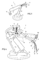
La figure 1 annexée à la présente description illustre très
schématiquement un exemple un robot de soudage 1 selon l'art connu muni
d'un faisceau de câble d'amenée de courant électrique.Figure 1 appended to this description illustrates very
schematically an example a
Le robot de soudage comprend habituellement un châssis fixé au sol
ou sur un support fixe 14. Il comprend également un bras articulé 10, constitué
sur la figure 1 de deux membres 11 et 12, et, à l'extrémité libre du membre 11,
un organe de soudage 13 à pinces. Il est naturellement prévu des organes de
motorisation (non représentés) mettant mouvement relatif les divers éléments
du bras et commandant la pince de soudage 13. On peut ainsi obtenir plusieurs
degrés de liberté de mouvement. Le nombre de degrés de liberté dépend du
type de robot utilisé et est adapté à l'application précise envisagée.The welding robot usually includes a chassis fixed to the ground
or on a
La fourniture de l'énergie nécessaire et éventuellement de signaux de
commande est réalisée de façon habituelle à l'aide d'un faisceau 2 de câbles,
trois dans l'exemple décrit sur la figure 1 : 20 à 22.Providing the necessary energy and possibly signaling
control is carried out in the usual way using a
Comme il vient d'être indiqué, le faisceau comprend également des conduites flexibles pour le transport de fluide.As just indicated, the bundle also includes flexible lines for fluid transport.
Notamment dans l'application préférée, mais pas exclusivement, les
membres, 11 et 12, du bras 10 sont animés de mouvements relatifs rapides et
répétés lors des processus de soudage. Il s'ensuit que les câbles, 20 à 22, du
faisceau 2 sont également constamment sollicités et subissent des contraintes
élevées : forces de traction et de torsion.Particularly in the preferred application, but not exclusively, the
limbs, 11 and 12, of
Il en résulte une durée de vie relativement faible.This results in a relatively short service life.
En outre, les câbles, 20 à 22, du faisceau 2 ne sont maintenus que par
leur base, points d'entrée dans le bras du robot 1.In addition, the cables, 20 to 22, of the
Cette caractéristique nuit à la fiabilité des attaches.This characteristic affects the reliability of the fasteners.
Elle ne permet pas non plus d'optimiser les trajectoires des membres du bras du robot.It also does not optimize the trajectories of the members of the robot arm.
L'invention vise à pallier les inconvénients des dispositifs de l'art connu, et dont certains viennent d'être rappelés.The invention aims to overcome the drawbacks of the devices of the art known, and some of which have just been recalled.
L'invention se fixe pour but un dispositif de maintien d'éléments de faisceau de transport d'énergie pour automate comprenant des parties mobiles alimentées par ces éléments répondant aux besoins qui viennent d'être évoquésThe invention sets itself the goal of a device for holding elements of energy transport bundle for a machine comprising moving parts powered by these elements meeting the needs that have just been evoked
Pour ce faire, selon une caractéristique importante, les éléments précités, câbles ou conduites flexibles, sont supportés par un bras de renvoi, mobile en rotation autour d'un arbre assujetti à une partie mobile de l'automate par un premier organe de fixation. L'arbre est coaxial à un ressort, de type boudin ou similaire, dont une des extrémité est solidaire de l'organe de fixation, l'autre étant solidaire du bras de renvoi et exerce une force de rappel quand celui-ci s'écarte d'une position que l'on appellera initiale ou de repos. To do this, according to an important characteristic, the elements mentioned above, flexible cables or conduits, are supported by a deflection arm, movable in rotation around a shaft subject to a movable part of the automaton by a first fixing member. The shaft is coaxial with a spring, of the type sausage or the like, one end of which is integral with the fixing member, the other being integral with the deflection arm and exerts a restoring force when this deviates from a position that will be called initial or rest.
Dans une variante préférée de l'invention, les éléments du faisceau sont en outre enfilés dans une gaine, avantageusement en plastique souple. La gaine accompagne le faisceau sur une longueur déterminée.In a preferred variant of the invention, the elements of the bundle are also threaded in a sheath, preferably made of flexible plastic. The sheath accompanies the beam over a determined length.
Enfin, toujours de façon préférentielle, l'extrémité de la gaine par laquelle sont introduits les éléments du faisceau est elle-même assujettie à l'automate par un second organe de fixation.Finally, still preferably, the end of the sheath by which are introduced the elements of the beam is itself subject to the automaton by a second fixing member.
Cette disposition permet un maintien et un guidage efficace de l'élément de faisceau dans la zone de sortie.This arrangement allows effective maintenance and guidance of the beam element in the exit area.
Elle présente plusieurs avantages et notamment les avantages suivants :
- l'amélioration de la maintenabilité des faisceaux ;
- l'amélioration de la durée de vie des faisceaux, en particulier en réduisant les contraintes précitées de traction et de torsion ; et
- la réduction de l'encombrement des faisceaux autour des zones d'axes des robots, car ceux-ci sont mieux dirigés, ce qui permet d'accroítre l'optimisation des trajectoires.
- improving the maintainability of beams;
- improving the service life of the beams, in particular by reducing the aforementioned tensile and torsional stresses; and
- reducing the size of the beams around the axis areas of the robots, because they are better directed, which allows to optimize the trajectories.
L'invention a donc pour objet principal un dispositif de maintien d'éléments de faisceau d'alimentation en énergie d'un automate comprenant au moins une partie mobile reliée au dit faisceau, caractérisé en ce qu'il comprend au moins un bras dit de renvoi, supportant au moins un élément dudit faisceau, en ce que une première extrémité dudit bras renvoi est mobile en rotation autour d'une première extrémité d'un arbre, suivant un premier axe, en ce que ledit arbre est assujetti, en une seconde extrémité, à un premier organe de fixation solidaire de ladite partie mobile, en ce que ledit arbre est associé à des moyens à ressort exerçant sur ledit bras de renvoi une force de rappel vers une position déterminée dans l'espace, dite de repos, par rapport au dit arbre, de manière à obtenir un maintien et un guidage dudit élément lors des déplacements dans l'espace de ladite partie mobile.The main object of the invention is therefore a holding device elements of the energy supply bundle of a PLC comprising at at least one movable part connected to said beam, characterized in that it comprises at least one so-called deflection arm, supporting at least one element of said beam, in that a first end of said deflection arm is movable in rotation around a first end of a tree, along a first axis, in that said shaft is subject, at a second end, to a first member of fixed attachment to said movable part, in that said shaft is associated with spring means exerting on said deflection arm a restoring force towards a determined position in space, called rest, relative to said tree, of so as to maintain and guide said element during displacements in the space of said movable part.
L'invention a encore pour objet l'application d'un tel dispositif à un robot de soudage dont le bras est alimenté par un faisceau de câbles d'amenée d'énergie électrique et de conduites flexibles véhiculant des fluides. The invention also relates to the application of such a device to a welding robot whose arm is supplied by a bundle of supply cables of electrical energy and flexible pipes carrying fluids.
L'invention va maintenant être décrite de façon plus détaillée en se référant aux dessins annexés, parmi lesquels :
- la figure 1 illustre très schématiquement un exemple de robot de soudage alimenté en énergie électrique par un faisceau de câbles selon l'art connu ;
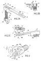
- les figures 2A à 2C illustrent schématiquement un dispositif de maintien de câbles électriques d'un faisceau selon un mode de réalisation préféré de l'invention ;
- la figure 3 illustre un second organe de maintien de câbles électriques d'un faisceau ; et
- la figure 4 illustre un robot de soudage muni d'un dispositif de maintien de faisceau selon un mode de réalisation préféré de l'invention.
- FIG. 1 very schematically illustrates an example of a welding robot supplied with electrical energy by a bundle of cables according to the prior art;
- FIGS. 2A to 2C schematically illustrate a device for holding electrical cables from a bundle according to a preferred embodiment of the invention;
- FIG. 3 illustrates a second member for holding electrical cables from a bundle; and
- FIG. 4 illustrates a welding robot provided with a beam holding device according to a preferred embodiment of the invention.
Dans ce qui suit, sans en limiter en quoi que ce soit la portée, on se placera ci-après dans le cadre de l'application préférée de l'invention, sauf mention contraire, c'est-à-dire dans le cas d'un robot de soudage pour l'industrie automobile.In what follows, without limiting its scope in any way, we will will place below in the context of the preferred application of the invention, except otherwise stated, i.e. in the case of a welding robot for automobile industry.
En soi, la configuration du robot de soudage est identique ou pour le moins très semblable à celle d'un robot de l'art connu. Les composants de ce robots ne nécessitent donc pas d'être re-décrits de façon détaillée.In itself, the configuration of the welding robot is identical or for the less very similar to that of a known art robot. The components of this robots therefore do not need to be described again in detail.
On va maintenant décrire, en se référant aux figures 2A à 4, un
exemple de réalisation de dispositif 3 de maintien d'éléments de faisceau, en
l'occurrence de câble d'alimentation d'énergie électrique, selon un mode de
réalisation préféré de l'invention, et un exemple de robot 7 muni d'un tel
dispositif 3.We will now describe, with reference to FIGS. 2A to 4, a
exemplary embodiment of a
Sur ces figures, les éléments identiques portent les mêmes références et ne seront re-décrits qu'en tant que de besoin.In these figures, identical elements have the same references and will only be re-described as necessary.
La figure 2A illustre le dispositif 3 en perspective.FIG. 2A illustrates the
Selon une caractéristique principale, le dispositif 3 comprend un bras
support 30, que l'on appellera de renvoi. De façon avantageuse, il est constitué
par un membre parallélépipédique rectangle 30 assujetti en une extrémité à un
bloc 31, également sensiblement parallélépipédique rectangle. La fixation est
réalisée par tous moyens appropriés, vis ou autre, sous la référence unique
301. Le bloc 31 est percé de part en part, cavité 310, de façon à y loger un
arbre 32, d'axe de symétrie Δ orthogonal au plan que forme le bras support 30.According to a main characteristic, the
Pour que ce dernier puisse se mouvoir en rotation libre autour de
l'arbre 32, on prévoit avantageusement un roulement à billes 36 logé dans la
cavité 310 ou tout organe de fonction similaire.So that the latter can move in free rotation around
the
Selon une autre caractéristique importante, l'arbre 32 est associé à
des moyens à ressort 35, avantageusement de type à boudin. Dans l'exemple
décrit, l'arbre 32 est coaxial à au ressort 35. L'arbre 32 et le ressort 35 sont
assujettis en leurs extrémités, que l'on dira arbitrairement inférieures, à un
organe de fixation 34, le ressort étant en outre fixé par un clip ou tout autre
organe 33. L'organe de fixation 34 est lui-même assujetti à l'automate, comme
il le sera montré en regard de la figure 4, par tout moyen approprié, vis ou
autre, 340 et 341.According to another important characteristic, the
La figure 2B est une figure de détail montrant le dispositif en coupe
partielle, de façon à mettre en évidence la coopération de l'arbre de rotation 32,
de l'extrémité correspondante du ressort 35 et du bloc 31 auquel est fixé le bras
de renvoi 30.Figure 2B is a detail figure showing the device in section
partial, so as to highlight the cooperation of the
De façon plus particulière, l'extrémité du ressort 35 se prolonge dans le
bloc 31 par un doigt 350More particularly, the end of the
De ce fait, si on se reporte de nouveau à la figure 2A, lorsque le bras
de renvoi est mis en rotation autour de l'axe Δ et s'éloigne (angle α) d'une
position que l'on appellera initiale ou de repos, symbolisée par un axe
longitudinale Δ', le ressort 32 va être soumis à des efforts de torsion. Il s'ensuit
que celui-ci, à son tour, exerce une force ou couple de rappel sur le bras de
renvoi 30, via le doigt 350 et le bloc 31, qui tend à le ramener à la position de
repos précitée, ce quelque soit le sens de l'angle α.Therefore, if we refer again to Figure 2A, when the arm
deflection is rotated around the axis Δ and moves away (angle α) by
position which will be called initial or rest, symbolized by an axis
longitudinal Δ ', the
Selon une autre caractéristique importante encore, le faisceau 2 est
rendu solidaire du bras de renvoi 30.According to yet another important characteristic, the
De façon préférentielle, l'assujettissement au bras de renvoi 30 n'est
pas rigide. Preferably, the subjection to the
La figure 2C illustre de façon plus particulière un exemple de
réalisation préféré de moyens d'attache 5 du faisceau 2 au bras de renvoi 30.FIG. 2C more particularly illustrates an example of
preferred embodiment of
Le bras de renvoi 30 est muni avantageusement d'un certain nombre
de trous répartis le long de son axe longitudinal Δ'. Ces trous permettent de
fixer sur sa paroi, que l'on appellera supérieure, de façon réglable, une platine
50 supportant l'extrémité dite inférieure d'un arbre de rotation 51 dont
l'extrémité dite supérieure supporte elle-même, rotation libre, une bague de
fixation 53 du faisceau.The
De façon avantageuse, celle-ci est composée de deux demi-coques,
530 et 531, pouvant s'ouvrir, de manière à y introduire le faisceau 2. On prévoit
également un organe de verrouillage/déverrouillage 532, de manière à
solidariser les deux demi-coquilles, 530 et 531, lorsque le faisceau 2 est inséré
entre celles-ci. Il peut s'agir d'un organe à boucle 532, de type levier, ou tout
autre organe approprié.Advantageously, it is composed of two half-shells,
530 and 531, which can be opened, so as to introduce the
Par ces dispositions, la bague de fixation 50 peut se mouvoir en
rotation autour de l'axe de symétrie Δ" de l'arbre 51.By these provisions, the fixing
De façon préférentielle également, les câbles composant le faisceau 2
ne sont pas enfilés nus dans les moyens d'attache 5. On les enfile au préalable
dans une gaine flexible 4, par exemple en plastique, du type "accordéon". Cette
gaine 4 accompagne les câbles du faisceau 2 sur un longueur déterminée ℓ, à
partir du bras de l'automate 7, comme il le sera montré ultérieurement par
référence plus particulière à la figure 4.Also preferably, the cables making up the
Toujours de façon préférentielle, à l'extrémité libre de la gaine 4,
comme illustré par la figure 3, on prévoit un organe de fixation 6 de cette
extrémité à l'automate 7.Still preferably, at the free end of the sheath 4,
as illustrated in Figure 3, there is provided a
De façon avantageuse, l'organe de fixation 6 comprend une bague 60,
de préférence double : deux réceptacles, 600 et 601 réunis par un organe de
verrouillage/déverrouillage 602, par exemple à vis. Cette bague 60 emprisonne
un organe, que l'on appellera "noix" 63, percé de part en part par des canaux,
630 à 632 dans l'exemple décrit. On enfile dans les canaux, 630 à 632, les
différents câbles, 20 à 22, du faisceau 2. Le matériau constituant la "noix" 63
est un matériau souple, par exemple du plastique, de façon à maintenir les
câbles, 20 à 22, sans les blesser.Advantageously, the fixing
La bague 60 comprend des moyens de fixation 61 à une zone
appropriée de l'automate 7.The
On va maintenant décrire un exemple d'automate muni dispositif de
maintien de faisceau 2 du type qui vient d'être décrit en regard des figures 2A à
3, conformément à un mode de réalisation préféré de l'invention.We will now describe an example of an automaton equipped with a
On a référencé sur la figure 4 que les composants nécessaires à la bonne compréhension de l'invention, l'automate, en soi pouvant être d'un type quelconque, notamment conforme à l'art connu.Reference has been made in FIG. 4 that the components necessary for the good understanding of the invention, the automaton per se being of a type any, in particular in accordance with known art.
Dans l'exemple décrit sur la figure 4, l'automate 7 consiste plus
particulièrement en un appareil appelé manipulateur. Le système complet
comprend en outre un appareil de commande (non représenté) d'où partent les
câbles composant le faisceau 2.In the example described in FIG. 4, the
Le manipulateur 7 comprend un bras articulé 70 comportant deux
séries de membres reliées entre eux, 71 et 72. L'extrémité libre du bras 72 est
munie d'un porte-outil 720 destiné, par exemple, à recevoir des pinces de
soudage (non représentées). L'ensemble repose sur un châssis fixe 74.The
Dans l'exemple décrit, le faisceau 2, dans sa gaine 4, entre dans le
bras 70 par l'extrémité du bras 72 proche d'une zone d'articulation 721 entre les
deux membres, 71 et 72.In the example described, the
Le dispositif 3 est disposé en partie supérieure du manipulateur 7, dans
une zone du membre 72 proche de l'articulation 721.The
On peut prévoir, en tant que de besoin, une platine de fixation 8,
solidaire du membre 72, sur laquelle le dispositif est assujetti via l'organe de
fixation 33-34.One can provide, as necessary, a fixing
Lorsque, notamment, le membre 72 se déplace dans l'espace, le
dispositif 3 accompagne ces déplacements et guide et soutient efficacement le
faisceau 2 dans sa gaine 4, l'une des extrémités de celle-ci étant prisonnière du
membre 72. When, in particular, the
Comme il a été décrit en regard de la figure 3, l'autre extrémité, dans
une variante de réalisation préférée est assujettie, grâce aux moyens de
fixation 6, à l'automate, de façon avantageuse à l'extrémité du membre 72.As described with reference to FIG. 3, the other end, in
a preferred embodiment is subject, thanks to the means of
On peut également prévoir des bagues de maintien intermédiaires 9,
enfilées à intervalles réguliers le long de la gaine 4, la longueur de cette
dernière étant égale à ℓ, à partir de l'entrée des câbles dans le membre 72.It is also possible to provide intermediate retaining rings 9,
strung at regular intervals along the sheath 4, the length of this
the latter being equal to ℓ, from the entry of the cables in the
La position exacte du dispositif 3 (et de son axe de rotation Δ) et la
longueur du bras de renvoi 30 sont déterminées en fonction de divers
paramètres qui dépendent de l'application envisagée, notamment des
dimensions des composants du bras 70 et du degré de rotation à obtenir, de
manière à ce que, quelles que soient les positions relatives des deux séries de
membres 71 et 72, on obtienne le maintien et le guidage désirés du faisceau.
De même, la raideur du ressort est déterminée en fonction des paramètres
géométriques et autres associés au faisceau 2 (propre raideur du faisceau, sa
masse, etc.).The exact position of the device 3 (and of its axis of rotation Δ) and the
length of the
A la lecture de ce qui précède, on constate aisément que l'invention atteint bien les buts qu'elle s'est fixés.On reading the above, it can easily be seen that the invention achieves the goals it has set for itself.
Il doit être clair cependant que l'invention n'est pas limitée aux seuls exemples de réalisations explicitement décrits, notamment en relation avec les figures 2A à 4.It should be clear, however, that the invention is not limited to only examples of achievements explicitly described, in particular in relation to Figures 2A to 4.
Enfin, bien que le dispositif ait été décrit de façon détaillée dans le cas spécifique d'un bras articulé pour robot de soudage pour l'industrie automobile, l'invention, comme il a été précédemment indiqué, n'est en aucun cas limité à cette application particulière.Finally, although the device has been described in detail in the case specific of an articulated arm for a welding robot for the automotive industry, the invention, as previously indicated, is in no way limited to this particular app.
Le dispositif selon l'invention peut trouver application pour tout automate comprenant des parties mobiles alimentées par des éléments de faisceau d'amenée d'énergie, tant électrique que fluidique, comme il a été rappelé.The device according to the invention can find application for any automaton comprising moving parts supplied by elements of energy supply beam, both electric and fluid, as it was recalled.
Claims (10)
Applications Claiming Priority (2)
| Application Number | Priority Date | Filing Date | Title |
|---|---|---|---|
| FR0110804 | 2001-08-14 | ||
| FR0110804A FR2828655B1 (en) | 2001-08-14 | 2001-08-14 | DEVICE FOR HOLDING ENERGY TRANSPORT BEAM ELEMENTS TO AN AUTOMATON AND ITS APPLICATION TO A WELDING ROBOT |
Publications (2)
| Publication Number | Publication Date |
|---|---|
| EP1284177A1 true EP1284177A1 (en) | 2003-02-19 |
| EP1284177B1 EP1284177B1 (en) | 2006-11-15 |
Family
ID=8866522
Family Applications (1)
| Application Number | Title | Priority Date | Filing Date |
|---|---|---|---|
| EP02291983A Expired - Lifetime EP1284177B1 (en) | 2001-08-14 | 2002-08-07 | Device for holding a bundle of energy supply cables on a welding robot |
Country Status (4)
| Country | Link |
|---|---|
| EP (1) | EP1284177B1 (en) |
| AT (1) | ATE345200T1 (en) |
| DE (1) | DE60216019D1 (en) |
| FR (1) | FR2828655B1 (en) |
Cited By (1)
| Publication number | Priority date | Publication date | Assignee | Title |
|---|---|---|---|---|
| DE102021127283A1 (en) | 2021-10-21 | 2023-04-27 | Murrplastik Systemtechnik Gmbh | Device for guiding cables |
Families Citing this family (1)
| Publication number | Priority date | Publication date | Assignee | Title |
|---|---|---|---|---|
| DE102022123623A1 (en) * | 2022-09-15 | 2024-03-21 | Dürr Systems Ag | Resetting device for resetting at least one line |
Citations (5)
| Publication number | Priority date | Publication date | Assignee | Title |
|---|---|---|---|---|
| US4705243A (en) * | 1983-10-19 | 1987-11-10 | Kuka Schweissanlangen | System of externally holding and guiding supply lines to moving implements of manipulators |
| DE9217659U1 (en) * | 1992-12-24 | 1994-04-07 | Kuka Schweissanlagen & Roboter | Cable routing for a supply line on a multi-axis robot |
| FR2724866A1 (en) * | 1994-09-27 | 1996-03-29 | Caty Polymeres Sa | Industrial robot universal superstructure for improved response |
| DE20010696U1 (en) * | 2000-06-15 | 2001-07-26 | Kuka Roboter Gmbh | Device for fixing cables of a cable routing hose |
| US20020007692A1 (en) * | 2000-07-14 | 2002-01-24 | Torbjorn Albertsson | Manipulator |
-
2001
- 2001-08-14 FR FR0110804A patent/FR2828655B1/en not_active Expired - Fee Related
-
2002
- 2002-08-07 DE DE60216019T patent/DE60216019D1/en not_active Expired - Lifetime
- 2002-08-07 AT AT02291983T patent/ATE345200T1/en not_active IP Right Cessation
- 2002-08-07 EP EP02291983A patent/EP1284177B1/en not_active Expired - Lifetime
Patent Citations (5)
| Publication number | Priority date | Publication date | Assignee | Title |
|---|---|---|---|---|
| US4705243A (en) * | 1983-10-19 | 1987-11-10 | Kuka Schweissanlangen | System of externally holding and guiding supply lines to moving implements of manipulators |
| DE9217659U1 (en) * | 1992-12-24 | 1994-04-07 | Kuka Schweissanlagen & Roboter | Cable routing for a supply line on a multi-axis robot |
| FR2724866A1 (en) * | 1994-09-27 | 1996-03-29 | Caty Polymeres Sa | Industrial robot universal superstructure for improved response |
| DE20010696U1 (en) * | 2000-06-15 | 2001-07-26 | Kuka Roboter Gmbh | Device for fixing cables of a cable routing hose |
| US20020007692A1 (en) * | 2000-07-14 | 2002-01-24 | Torbjorn Albertsson | Manipulator |
Cited By (1)
| Publication number | Priority date | Publication date | Assignee | Title |
|---|---|---|---|---|
| DE102021127283A1 (en) | 2021-10-21 | 2023-04-27 | Murrplastik Systemtechnik Gmbh | Device for guiding cables |
Also Published As
| Publication number | Publication date |
|---|---|
| EP1284177B1 (en) | 2006-11-15 |
| ATE345200T1 (en) | 2006-12-15 |
| FR2828655B1 (en) | 2003-11-07 |
| DE60216019D1 (en) | 2006-12-28 |
| FR2828655A1 (en) | 2003-02-21 |
Similar Documents
| Publication | Publication Date | Title |
|---|---|---|
| EP2476502B1 (en) | Sheet-metal clamp used in combination with a manipulator arm and having an offset balancing module | |
| BE898154A (en) | Manipuleur for positioning workpieces or other loads. | |
| EP0388293A1 (en) | Drive belt tensioning device | |
| FR2671752A1 (en) | CLAMP ACTUATOR SYSTEM FOR A FIXING FRAME SUPPORTED BY A CONVEYOR. | |
| CA1292030C (en) | Mechanical energy storage device | |
| EP1284177B1 (en) | Device for holding a bundle of energy supply cables on a welding robot | |
| FR2491380A1 (en) | MANIPULATOR ROBOT, IN PARTICULAR FOR THE AUTOMATIC POSITIONING OF MACHINING PARTS | |
| FR2670424A1 (en) | MANIPULATOR DEVICE FOR MOVING AN OBJECT, IN SPACE, PARALLEL TO HIMSELF. | |
| EP1304195A1 (en) | Holding device for a cable bundle supplying energy to an automaton and its use for a welding robot | |
| FR2574334A1 (en) | MANIPULATION SYSTEM FOR MOUNTING COMPONENTS | |
| EP0109405B1 (en) | Device for gripping articles for robot-type manipulator | |
| EP1072366A1 (en) | Conveyor apparatus | |
| FR2604138A1 (en) | Device for holding overhead cables driven in advancement in line at a pylon, and overhead cable transportation installation comprising such a device | |
| EP3546141A1 (en) | Device with cables for the application of equal forces on at least two points distant from one another | |
| FR2713728A1 (en) | Device for fast clamping of moving parts in a passenger compartment of vehicles. | |
| FR2564023A1 (en) | Tool-carrying gripper | |
| EP0190062B1 (en) | Adjustable support for the mirror in a following spotlight | |
| FR2581914A1 (en) | Component-gripping device for manipulating robot | |
| FR2610562A1 (en) | Articulated handling gripper with five degrees of freedom | |
| EP0093042A1 (en) | Self-adapting and vibration-damping clamping device | |
| FR2569638A1 (en) | Rear view mirror for a vehicle comprising particular articulation means | |
| FR2692514A1 (en) | Supple mechanical interface between robot grip and tool it holds - uses plates separated by pneumatic actuators and joined by swivel joint that allows limited three-axis movement. | |
| FR2678193A1 (en) | Robot for welding using a laser beam | |
| EP4149722A1 (en) | Device for carrying out interventions on an electrical transmission line assembly | |
| FR2548104A1 (en) | Device for electrically powering an armoured vehicle cupola |
Legal Events
| Date | Code | Title | Description |
|---|---|---|---|
| PUAI | Public reference made under article 153(3) epc to a published international application that has entered the european phase |
Free format text: ORIGINAL CODE: 0009012 |
|
| AK | Designated contracting states |
Designated state(s): AT BE BG CH CY CZ DE DK EE ES FI FR GB GR IE IT LI LU MC NL PT SE SK TR |
|
| AX | Request for extension of the european patent |
Extension state: AL LT LV MK RO SI |
|
| 17P | Request for examination filed |
Effective date: 20030527 |
|
| AKX | Designation fees paid |
Designated state(s): AT BE BG CH CY CZ DE DK EE ES FI FR GB GR IE IT LI LU MC NL PT SE SK TR |
|
| GRAP | Despatch of communication of intention to grant a patent |
Free format text: ORIGINAL CODE: EPIDOSNIGR1 |
|
| GRAS | Grant fee paid |
Free format text: ORIGINAL CODE: EPIDOSNIGR3 |
|
| GRAA | (expected) grant |
Free format text: ORIGINAL CODE: 0009210 |
|
| AK | Designated contracting states |
Kind code of ref document: B1 Designated state(s): AT BE BG CH CY CZ DE DK EE ES FI FR GB GR IE IT LI LU MC NL PT SE SK TR |
|
| PG25 | Lapsed in a contracting state [announced via postgrant information from national office to epo] |
Ref country code: IT Free format text: LAPSE BECAUSE OF FAILURE TO SUBMIT A TRANSLATION OF THE DESCRIPTION OR TO PAY THE FEE WITHIN THE PRESCRIBED TIME-LIMIT;WARNING: LAPSES OF ITALIAN PATENTS WITH EFFECTIVE DATE BEFORE 2007 MAY HAVE OCCURRED AT ANY TIME BEFORE 2007. THE CORRECT EFFECTIVE DATE MAY BE DIFFERENT FROM THE ONE RECORDED. Effective date: 20061115 Ref country code: FI Free format text: LAPSE BECAUSE OF FAILURE TO SUBMIT A TRANSLATION OF THE DESCRIPTION OR TO PAY THE FEE WITHIN THE PRESCRIBED TIME-LIMIT Effective date: 20061115 Ref country code: SK Free format text: LAPSE BECAUSE OF FAILURE TO SUBMIT A TRANSLATION OF THE DESCRIPTION OR TO PAY THE FEE WITHIN THE PRESCRIBED TIME-LIMIT Effective date: 20061115 Ref country code: NL Free format text: LAPSE BECAUSE OF FAILURE TO SUBMIT A TRANSLATION OF THE DESCRIPTION OR TO PAY THE FEE WITHIN THE PRESCRIBED TIME-LIMIT Effective date: 20061115 Ref country code: CZ Free format text: LAPSE BECAUSE OF FAILURE TO SUBMIT A TRANSLATION OF THE DESCRIPTION OR TO PAY THE FEE WITHIN THE PRESCRIBED TIME-LIMIT Effective date: 20061115 Ref country code: AT Free format text: LAPSE BECAUSE OF FAILURE TO SUBMIT A TRANSLATION OF THE DESCRIPTION OR TO PAY THE FEE WITHIN THE PRESCRIBED TIME-LIMIT Effective date: 20061115 Ref country code: IE Free format text: LAPSE BECAUSE OF FAILURE TO SUBMIT A TRANSLATION OF THE DESCRIPTION OR TO PAY THE FEE WITHIN THE PRESCRIBED TIME-LIMIT Effective date: 20061115 |
|
| REG | Reference to a national code |
Ref country code: GB Ref legal event code: FG4D Free format text: NOT ENGLISH |
|
| REG | Reference to a national code |
Ref country code: CH Ref legal event code: EP |
|
| REF | Corresponds to: |
Ref document number: 60216019 Country of ref document: DE Date of ref document: 20061228 Kind code of ref document: P |
|
| REG | Reference to a national code |
Ref country code: IE Ref legal event code: FG4D Free format text: LANGUAGE OF EP DOCUMENT: FRENCH |
|
| PG25 | Lapsed in a contracting state [announced via postgrant information from national office to epo] |
Ref country code: BG Free format text: LAPSE BECAUSE OF FAILURE TO SUBMIT A TRANSLATION OF THE DESCRIPTION OR TO PAY THE FEE WITHIN THE PRESCRIBED TIME-LIMIT Effective date: 20070215 Ref country code: DK Free format text: LAPSE BECAUSE OF FAILURE TO SUBMIT A TRANSLATION OF THE DESCRIPTION OR TO PAY THE FEE WITHIN THE PRESCRIBED TIME-LIMIT Effective date: 20070215 Ref country code: SE Free format text: LAPSE BECAUSE OF FAILURE TO SUBMIT A TRANSLATION OF THE DESCRIPTION OR TO PAY THE FEE WITHIN THE PRESCRIBED TIME-LIMIT Effective date: 20070215 |
|
| PG25 | Lapsed in a contracting state [announced via postgrant information from national office to epo] |
Ref country code: DE Free format text: LAPSE BECAUSE OF FAILURE TO SUBMIT A TRANSLATION OF THE DESCRIPTION OR TO PAY THE FEE WITHIN THE PRESCRIBED TIME-LIMIT Effective date: 20070216 |
|
| PG25 | Lapsed in a contracting state [announced via postgrant information from national office to epo] |
Ref country code: ES Free format text: LAPSE BECAUSE OF FAILURE TO SUBMIT A TRANSLATION OF THE DESCRIPTION OR TO PAY THE FEE WITHIN THE PRESCRIBED TIME-LIMIT Effective date: 20070226 |
|
| PG25 | Lapsed in a contracting state [announced via postgrant information from national office to epo] |
Ref country code: PT Free format text: LAPSE BECAUSE OF FAILURE TO SUBMIT A TRANSLATION OF THE DESCRIPTION OR TO PAY THE FEE WITHIN THE PRESCRIBED TIME-LIMIT Effective date: 20070416 |
|
| NLV1 | Nl: lapsed or annulled due to failure to fulfill the requirements of art. 29p and 29m of the patents act | ||
| GBV | Gb: ep patent (uk) treated as always having been void in accordance with gb section 77(7)/1977 [no translation filed] |
Effective date: 20061115 |
|
| REG | Reference to a national code |
Ref country code: IE Ref legal event code: FD4D |
|
| PLBE | No opposition filed within time limit |
Free format text: ORIGINAL CODE: 0009261 |
|
| STAA | Information on the status of an ep patent application or granted ep patent |
Free format text: STATUS: NO OPPOSITION FILED WITHIN TIME LIMIT |
|
| 26N | No opposition filed |
Effective date: 20070817 |
|
| PG25 | Lapsed in a contracting state [announced via postgrant information from national office to epo] |
Ref country code: GB Free format text: LAPSE BECAUSE OF FAILURE TO SUBMIT A TRANSLATION OF THE DESCRIPTION OR TO PAY THE FEE WITHIN THE PRESCRIBED TIME-LIMIT Effective date: 20061115 |
|
| BERE | Be: lapsed |
Owner name: CIMLEC INDUSTRIE Effective date: 20070831 |
|
| REG | Reference to a national code |
Ref country code: CH Ref legal event code: PL |
|
| PG25 | Lapsed in a contracting state [announced via postgrant information from national office to epo] |
Ref country code: GR Free format text: LAPSE BECAUSE OF FAILURE TO SUBMIT A TRANSLATION OF THE DESCRIPTION OR TO PAY THE FEE WITHIN THE PRESCRIBED TIME-LIMIT Effective date: 20070216 Ref country code: CH Free format text: LAPSE BECAUSE OF NON-PAYMENT OF DUE FEES Effective date: 20070831 Ref country code: LI Free format text: LAPSE BECAUSE OF NON-PAYMENT OF DUE FEES Effective date: 20070831 Ref country code: MC Free format text: LAPSE BECAUSE OF NON-PAYMENT OF DUE FEES Effective date: 20070831 |
|
| REG | Reference to a national code |
Ref country code: FR Ref legal event code: ST Effective date: 20080430 |
|
| PG25 | Lapsed in a contracting state [announced via postgrant information from national office to epo] |
Ref country code: BE Free format text: LAPSE BECAUSE OF NON-PAYMENT OF DUE FEES Effective date: 20070831 |
|
| PG25 | Lapsed in a contracting state [announced via postgrant information from national office to epo] |
Ref country code: FR Free format text: LAPSE BECAUSE OF NON-PAYMENT OF DUE FEES Effective date: 20070831 |
|
| PG25 | Lapsed in a contracting state [announced via postgrant information from national office to epo] |
Ref country code: EE Free format text: LAPSE BECAUSE OF FAILURE TO SUBMIT A TRANSLATION OF THE DESCRIPTION OR TO PAY THE FEE WITHIN THE PRESCRIBED TIME-LIMIT Effective date: 20061115 |
|
| PG25 | Lapsed in a contracting state [announced via postgrant information from national office to epo] |
Ref country code: LU Free format text: LAPSE BECAUSE OF NON-PAYMENT OF DUE FEES Effective date: 20070807 Ref country code: CY Free format text: LAPSE BECAUSE OF FAILURE TO SUBMIT A TRANSLATION OF THE DESCRIPTION OR TO PAY THE FEE WITHIN THE PRESCRIBED TIME-LIMIT Effective date: 20061115 |
|
| PG25 | Lapsed in a contracting state [announced via postgrant information from national office to epo] |
Ref country code: TR Free format text: LAPSE BECAUSE OF FAILURE TO SUBMIT A TRANSLATION OF THE DESCRIPTION OR TO PAY THE FEE WITHIN THE PRESCRIBED TIME-LIMIT Effective date: 20061115 |