EP1283586A1 - Permanent magnet synchronous linear motor - Google Patents
Permanent magnet synchronous linear motor Download PDFInfo
- Publication number
- EP1283586A1 EP1283586A1 EP01904526A EP01904526A EP1283586A1 EP 1283586 A1 EP1283586 A1 EP 1283586A1 EP 01904526 A EP01904526 A EP 01904526A EP 01904526 A EP01904526 A EP 01904526A EP 1283586 A1 EP1283586 A1 EP 1283586A1
- Authority
- EP
- European Patent Office
- Prior art keywords
- armature
- teeth
- linear motor
- length
- permanent magnets
- Prior art date
- Legal status (The legal status is an assumption and is not a legal conclusion. Google has not performed a legal analysis and makes no representation as to the accuracy of the status listed.)
- Granted
Links
Images


Classifications
-
- H—ELECTRICITY
- H02—GENERATION; CONVERSION OR DISTRIBUTION OF ELECTRIC POWER
- H02K—DYNAMO-ELECTRIC MACHINES
- H02K41/00—Propulsion systems in which a rigid body is moved along a path due to dynamo-electric interaction between the body and a magnetic field travelling along the path
- H02K41/02—Linear motors; Sectional motors
- H02K41/03—Synchronous motors; Motors moving step by step; Reluctance motors
-
- H—ELECTRICITY
- H02—GENERATION; CONVERSION OR DISTRIBUTION OF ELECTRIC POWER
- H02K—DYNAMO-ELECTRIC MACHINES
- H02K41/00—Propulsion systems in which a rigid body is moved along a path due to dynamo-electric interaction between the body and a magnetic field travelling along the path
- H02K41/02—Linear motors; Sectional motors
- H02K41/03—Synchronous motors; Motors moving step by step; Reluctance motors
- H02K41/031—Synchronous motors; Motors moving step by step; Reluctance motors of the permanent magnet type
Definitions
- This invention relates to a permanent magnet synchronous linear motor that has a reduced cogging thrust and that is superior in performance.
- a permanent magnet synchronous linear motor that is used for a feed mechanism of a machine tool or for a positioning device of a semiconductor manufacturing apparatus and that includes permanent magnets constituting a field pole and an armature facing the pole face of the permanent magnets through an air gap and in which an armature winding is wound in a slot of an armature core.
- a cogging thrust is generated due to an edge effect at both ends of the armature core when the armature is moved in the longitudinal direction of the magnet array of the permanent magnets due to an electromagnetic effect with the permanent magnets in a state where an electric current is not passed through the armature winding of such a structured linear motor.
- a linear motor that has auxiliary teeth at both ends of the armature core has been proposed as a conventional technique described as follows.
- FIG. 5 is a side sectional view of a permanent magnet synchronous linear motor that shows a first conventional technique that uses the 8-pole and 9-slot gap-opposed type (see JP,7-053427,Y2 for example).
- 1 is a flat field yoke
- 2 is a plurality of permanent magnets disposed on the field yoke 1 so as to alternate the polarity thereof
- 10 is an armature facing the pole face of the permanent magnet 2 through an air gap
- 11 is an armature core in which an electromagnetic steel plate is pectinately cut and in which an armature-core disc that has main teeth 11b forming slots 11a and a yoke portion 11c by which main teeth 11b are connected is placed and fixed thereto.
- 12 is an armature winding wound and contained in the slot 11a.
- 13 are auxiliary teeth provided at both ends of the armature core 11, and the length Ht of the main teeth 11b is equal to the length Hd of the auxiliary teeth 13.
- the permanent magnets 2 provided on the field yoke 1 serve as a stator
- the armature 10 serves as a movable part and runs in the longitudinal direction of the field yoke 1.
- JP,60-30195,B can be mentioned as a second conventional technique.
- the distance between the centers of the auxiliary teeth is specified as mentioned above as a countermeasure for which an edge effect at the ends of the armature core is removed, but the intention to improve performance in accordance with the usage of the linear motor conversely narrows design freedom, and therefore a cogging thrust cannot be reduced, and, disadvantageously, difficulties in improving the performance of the linear motor cannot be eliminated.
- the distance between the centers of the auxiliary teeth which is specified by the conventional techniques, is calculated in consideration of a primary component in which a change occurs in the ratio of 1 cycle to 1 magnetic-pole pitch. Therefore, a great reducing effect is brought about on the primary component, but, if a secondary component or a high-order component is contained in a cogging waveform, a reducing effect on the high-order component is small, and a situation occurs in which cogging cannot be reduced.
- the present invention has been made to solve the problems, and it is an object of the present invention to provide a high-performance permanent magnet synchronous linear motor that has a reduced cogging thrust.
- a permanent magnet synchronous linear motor comprises a field yoke having a plurality of permanent magnets which constitute fieldpoles so that the polarity thereof is alternated and which are arranged linearly and an armature facing an array of the permanent magnets through a magnetic air gap
- the invention of Claim 2 is characterized in that, in the permanent magnet synchronous linear motor according to Claim 1, the width Bd of the auxiliary teeth along the longitudinal direction of the array of the permanent magnets is set to be narrower than the width Bt of the main teeth along the longitudinal direction of the array of the permanent magnets.
- the invention of Claim 3 is characterized in that, in the permanent magnet synchronous linear motor according to Claim 1 or Claim 2, the ratio Hd/Ht of the length Hd of the auxiliary teeth to the length Ht of the main teeth is set to be 0.5 ⁇ Hd/Ht ⁇ 1.
- the invention of Claim 4 is characterized in that, in the permanent magnet synchronous linear motor according to any one of Claims 1 through Claim 3, the armature core is made up of a plurality of divided cores, and is formed such that a convex engagement part is provided on a side face of a yoke portion that constitutes the divided cores, and a concave engagement part is provided on an opposite side face thereof, and thereafter adjoining parts of the engagement parts are fitted and coupled with each other.
- a permanent magnet synchronous linear motor comprises a field yoke having a plurality of permanent magnets which constitute field poles so that the polarity thereof is alternated and which are arranged linearly and an armature facing the array of the permanent magnets through a magnetic air gap
- the armature comprises an armature core having main teeth and slots, an armature winding wound in the slots of the armature core, and auxiliary teeth provided at both ends of the armature core and in which the center-to-center distance ⁇ p of the auxiliary teeth and the pitch ⁇ m of the field poles satisfy a relationship ⁇ p ⁇ (2n-1) ⁇ ⁇ m /2 (n is a positive integer) and in which the field pole and the armature are relatively moved under the condition that one of the field pole and the armature is caused to serve as a stationary element and the other one is caused to serve as a movable element, wherein the length of the auxiliary teeth results in a relationship
- the invention of Claim 6 is characterized in that, in the permanent magnet synchronous linear motor according to Claim 5, the ratio Hd/Ht of the length Hd of the auxiliary teeth to the length Ht of the main teeth is set to be 0.5 ⁇ Hd/Ht ⁇ 1.
- the invention of Claim 7 is characterized in that, in the permanent magnet synchronous linear motor according to Claim 5 or Claim 6, the armature core is made up of a plurality of divided cores, and is formed such that a convex engagement part is provided on a side face of a yoke portion that constitutes the divided cores, and a concave engagement part is provided on an opposite side face thereof, and thereafter adjoining parts of the engagement parts are fitted and coupled with each other.
- a permanent magnet synchronous linear motor comprises a field yoke having a plurality of permanent magnets which constitute field poles so that the polarity thereof is alternated and which are arranged linearly and an armature facing the array of the permanent magnets through a magnetic air gap
- the armature comprises an armature core having main teeth and slots, an armature winding wound in the slots of the armature core, and auxiliary teeth provided at both ends of the armature core, and in which the field pole and the armature are relatively moved under the condition that one of the field pole and the armature is caused to serve as a stationary element and the other one is caused to serve as a movable element
- the center-to-center distance ⁇ p of the auxiliary teeth and the pitch ⁇ m of the field poles satisfy a relationship (2n-1) ⁇ m /8 ⁇ ⁇ p ⁇ (2n-1) ⁇ m /2 (n is a positive integer), and wherein the length of
- the invention of Claim 9 is characterized in that, in the permanent magnet synchronous linear motor according to Claim 8, the width Bd of the auxiliary teeth along the longitudinal direction of the array of the permanent magnets is set to be narrower than the width Bt of the main teeth along the longitudinal direction of the array of the permanent magnets.
- the invention of Claim 10 is characterized in that, in the permanent magnet synchronous linear motor according to Claim 9, the armature core is made up of a plurality of divided cores, and is formed such that a convex engagement part is provided on a side face of a yoke portion that constitutes the divided cores, and a concave engagement part is provided on an opposite side face thereof, and thereafter adjoining parts of the engagement parts are fitted and coupled with each other.
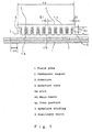
- FIG. 1 is a side sectional view of a permanent magnet synchronous linear motor showing the embodiment of the present invention, the linear motor being common in describing the relationship between main teeth and auxiliary teeth in the First through Third Embodiments.
- FIG. 2 shows an analytical result obtained by calculating a cogging thrust according to a numerical analysis in which the center-to-center distance ⁇ p of the auxiliary teeth and the length of the auxiliary teeth are used as parameters.
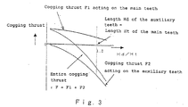
- FIG. 3 schematically shows the relationship between the ratio of the length of the auxiliary teeth to the length of the main teeth of an armature and a cogging thrust.
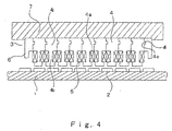
- FIG. 4 is a side sectional view of a permanent magnet synchronous linear motor showing a Fourth Embodiment of the present invention, the linear motor having divided cores.
- FIG. 5 is a side sectional view of a permanent magnet synchronous linear motor showing a first conventional technique.
- FIG. 1 is a side sectional view of a permanent magnet synchronous linear motor showing the embodiments of the present invention, the linear motor being common in describing the relationship between main teeth and auxiliary teeth in the First through Third Embodiments.
- the linear motor is the 8-pole and 9-slot gap-opposed type as in the conventional technique.
- 3 is an armature
- 4 is an armature core
- 4a is a slot
- 4b are main teeth
- 4c is a yoke portion
- 5 is an armature winding
- 6 are auxiliary teeth.
- the linear motor has a stationary element structured by permanent magnets 2 serving as field poles and a movable element structured by the armature 3 having the auxiliary teeth 6 at both ends of the armature core 4 that has the slots 4a and the main teeth 4b and in which the armature winding 5 is wound.
- the linear motor basically has the same structure as that of the conventional technique.
- a cogging thrust was calculated according to a numerical analysis using the finite element method on the supposition that the distance between the centers of the auxiliary teeth 6 is ⁇ p , the distance between the centers of the auxiliary teeth 6 shown in the conventional technique of FIG. 4 is ⁇ po , and the center-to-center distance ⁇ p of the auxiliary teeth 6 and the length Hd of the auxiliary teeth 6 are used as parameters.
- the length of the auxiliary teeth 6 in the direction orthogonal to the array of the permanent magnets 2 is represented as Hd
- the length of the main teeth 4b in the direction orthogonal to the array of the permanent magnets 2 is represented as Ht.
- FIG. 2 shows an analytical result obtained by calculating a cogging thrust according to a numerical analysis in which the center-to-center distance ⁇ p of the auxiliary teeth 6 and the length Hd of the auxiliary teeth 6 are used as parameters.
- the vertical axis represents a cogging thrust
- the horizontal axis represents the ratio ⁇ p / ⁇ po of the center-to-center distance ⁇ p of the auxiliary teeth 6 shown in FIG.1 to center-to-center distance ⁇ po of the auxiliary teeth 6 shown in FIG. 4 and represents the ratio Hd/Ht of the length Hd of the auxiliary teeth 6 to the length Ht of the main teeth 4b.
- the contour line equal in value to the cogging thrust is shown by connecting each calculation point like a lattice.
- FIG. 2 is shown by giving positive and negative signs to the cogging thrust, in consideration of the direction of the cogging thrust.
- FIG. 3 schematically shows the relationship between the ratio of the length of the auxiliary teeth 6 to the length of the main teeth 4b of an armature and a cogging thrust.
- the horizontal axis represents the ratio of the length of the auxiliary teeth 6 to the length of the main teeth 4b of an armature, and the vertical axis represents a cogging thrust. As in FIG. 2, positive and negative signs are given to the cogging thrust in consideration of the direction of the cogging thrust in FIG. 3.
- the cogging thrust F2 acting on the auxiliary teeth 6 and the thrust F1 acting on the armature 3 change according to the length of the auxiliary teeth 6.
- the optimum value of the length of the auxiliary teeth 6 where a cogging thrust reaches zero depends on the distance between the centers of the auxiliary teeth 6, the field-pole pitch, the length of the armature core 4, the width of the auxiliary teeth 6, etc. Referring to the optimum value, if the ratio Hd/Ht of the length Hd of the auxiliary teeth to the length Ht of the main teeth is set to be 0.5 ⁇ Hd/Ht ⁇ 1 from an analytical result of FIG. 3, the cogging thrust can be reduced to almost zero.
- width Bd of the auxiliary teeth 6 along the longitudinal direction of the array of the permanent magnets 2 is set to be narrower than the width Bt of the main teeth 4b along the longitudinal direction of the array of the permanent magnets under the aforementioned condition, it was verified that this width relationship is effective at further reducing the cogging thrust.
- the length of the auxiliary teeth 6 is set to be 0 ⁇ Hd ⁇ Ht where Hd is the length of the auxiliary teeth 6 in the direction orthogonal to the array of the permanent magnets 2 and Ht is the length of the main teeth 4b in the direction orthogonal to the array of the permanent magnets 2, under the condition that the relationship between the center-to-center distance ⁇ p of the auxiliary teeth 6 and the pitch ⁇ m of the field poles is set to be ⁇ p ⁇ (2n-1) x ⁇ m /2 (n is a positive integer).
- the ratio Hd/Ht of the length Hd of the auxiliary teeth 6 to the length Ht of the main teeth 4b is set to be 0.5 ⁇ Hd/Ht ⁇ 1.
- the cogging thrust can be reduced to almost zero as in the First Embodiment, and a high-performance permanent magnet synchronous linear motor that has a reduced cogging thrust can be provided.
- the cogging waveform of the linear motor has high-order components including or exceeding the secondary component with respect to the pole pitch besides the primary component. Its amplitude becomes larger proportionately with a decrease in order. Therefore, for cogging reduction, the primary component and the secondary component are especially required to be reduced.
- the center-to-center distance of the auxiliary teeth 6 by which the secondary component is removed is as follows.
- FL Fo sin[(2x/ ⁇ m )2 ⁇ ]
- FR Fo sin[(2x/ ⁇ m )2 ⁇ + (2 ⁇ p / ⁇ m) 2 ⁇ ]
- FL is a force acting on the left auxiliary teeth 6
- FR is a force acting on the right auxiliary teeth 6
- Fo is the amplitude of the secondary component
- x is the position of the armature core 4.
- the primary and secondary components can be simultaneously minimized by adjusting the length of the auxiliary teeth 6 though the center-to-center distance of the auxiliary teeth 6 by which the primary component is minimized is different from that of the auxiliary teeth 6 by which the secondary component is minimized.
- the length of the auxiliary teeth 6 has a greater influence on the primary component, and the primary component can be reduced by appropriately setting the length of the auxiliary teeth 6 even when the center-to-center distance of the auxiliary teeth 6 is arbitrary. In this situation, the magnitude of the secondary component also changes according to the length of the auxiliary teeth 6. According to an analytical result brought about by the finite element method, it was ascertained that a position where the secondary component is simultaneously minimized exists in the range of (2n-1) ⁇ m /8 ⁇ ⁇ p (2n-1) ⁇ m /2
- the center-to-center distance of the auxiliary teeth 6 is (2n-1) ⁇ m /8 ⁇ ⁇ p (2n-1) ⁇ m /2. Accordingly, the optimum center-to-center distance of the auxiliary teeth 6 can be calculated by, for example, a numerical analysis or experiment according to the finite element method.
- the primary and secondary components of a cogging waveform can be simultaneously reduced by setting the relationship between the field-pole pitch ⁇ m and the center-to-center distance ⁇ p of the auxiliary teeth as mentioned above, and therefore, as in the First and Second Embodiments, the cogging thrust can be reduced to almost zero, and a high-performance permanent magnet synchronous linear motor can be provided.
- FIG. 4 is a side sectional view of a permanent magnet synchronous linear motor having divided cores.
- an armature 3 of this linear motor is constructed such that an armature core 4 is divided into a plurality of core blocks, a convex engagement part 4d is then provided on one of the side faces of a yoke portion 4c that constitutes the divided core blocks whereas a concave engagement part 3e is provided on the other side face thereof, an armature winding 5 is then wound in the normal winding manner and is contained in a slot 4a of the core block, the engagement parts 4d and 4e of adjoining parts of the block cores are then fitted and united with each other, and, lastly, the united block cores are fixed to the undersurface of a movable element 7.
- the length of the armature can be freely increased or decreased in accordance with the specifications of the linear motor in the Fourth Embodiment, design freedom can be increased, and a cogging thrust can be reduced by combining the Fourth Embodiment with the structural features of the First through Third Embodiments when a demand to lengthen the stroke of the linear motor is made.
- teeth have been formed to be open slots in the embodiments, semi-open slots are permissible as shown in, for example, FIG. 4, and a cogging thrust can be reduced by appropriately setting the auxiliary teeth.
- linear motor has been described with reference to the gap-opposed type, it is permissible to dispose two-array field poles on both sides of the armature through a magnetic air gap so as to replace it with one of a magnetic-flux penetration type.
- the material of the auxiliary teeth is allowed to differ from that of the armature part, and may be appropriately selected.
- the present invention can have an effect by which the impedance unbalance between armature windings is restricted.
- the permanent magnet synchronous linear motor of the present invention is useful for a carrier system of an FA apparatus, such as a table feeder of a construction machine Or a stepper-driving mechanism of a semiconductor-manufacturing apparatus.
Landscapes
- Engineering & Computer Science (AREA)
- Physics & Mathematics (AREA)
- Chemical & Material Sciences (AREA)
- Combustion & Propulsion (AREA)
- Electromagnetism (AREA)
- Power Engineering (AREA)
- Linear Motors (AREA)
- Iron Core Of Rotating Electric Machines (AREA)
Abstract
Description
Claims (10)
- A permanent magnet synchronous linear motor comprising:a field yoke having a plurality of permanent magnets which constitute field poles so that a polarity thereof is alternated and which are arranged linearly, and an armature facing an array of the permanent magnets through a magnetic air gap;the armature comprising an armature core having main teeth and slots, an armature winding wound in the slot of the armature core, and auxiliary teeth provided at both ends of the armature core;a center-to-center distance τp of the auxiliary teeth and a pitch τm of the field pole satisfying a relationship of τp = (2n-1) x τm/2 (n is a positive integer);the field pole and the armature being relatively moved under the condition that one of the field pole and the armature is caused to serve as a stationary element and the other one is caused to serve as a movable element;the linear motor characterized in that the length of the auxiliary teeth is set to be in the range of 0 < Hd < Ht where Hd is the length of the auxiliary teeth in a direction orthogonal to the array of the permanent magnets and Ht is the length of the main teeth in the direction orthogonal to the array of the permanent magnets.
- The permanent magnet synchronous linear motor of Claim 1, characterized in that the width Bd of the auxiliary teeth along a longitudinal direction of the array of the permanent magnets is set to be narrower than the width Bt of the main teeth along the longitudinal direction of the array of the permanent magnets.
- The permanent magnet synchronous linear motor of Claim 1 or Claim 2, characterized in that a ratio Hd/Ht of the length Hd of the auxiliary teeth to the length Ht of the main teeth is set to be 0.5 ≤ Hd/Ht < 1.
- The permanent magnet synchronous linear motor of any one of Claims 1 through 3, characterized in that the armature core is made up of a plurality of divided cores, and is formed such that a convex engagement part is provided on a side face of a yoke portion that constitutes the divided cores whereas a concave engagement part is provided on an opposite side face thereof, and adjoining parts of the engagement parts are fitted and united with each other.
- A permanent magnet synchronous linear motor comprising:a field yoke having a plurality of permanent magnets which constitute field poles so that a polarity thereof is alternated and which are arranged linearly, and an armature facing an array of the permanent magnets through a magnetic air gap;the armature comprising an armature core having main teeth and slots, an armature winding wound in the slot of the armature core, and auxiliary teeth provided at both ends of the armature core;a center-to-center distance τp of the auxiliary teeth and a pitch τm of the field pole satisfying a relationship of τp ≠ (2n-1) × τm/2 (n is a positive integer);the field pole and the armature being relatively moved under the condition that one of the field pole and the armature is caused to serve as a stationary element and the other one is caused to serve as a movable element;the linear motor characterized in that the length of the auxiliary teeth is set to be in the range of 0 < Hd ≤ Ht where Hd is the length of the auxiliary teeth in a direction orthogonal to the array of the permanent magnets and Ht is the length of the main teeth in the direction orthogonal to the array of the permanent magnets.
- The permanent magnet synchronous linear motor of Claim 5, characterized in that a ratio Hd/Ht of the length Hd of the auxiliary teeth to the length Ht of the main teeth is set to be 0.5 ≤ Hd/Ht ≤ 1.
- The permanent magnet synchronous linear motor of Claim 5 or Claim 6, characterized in that the armature core is made up of a plurality of divided cores, and is formed such that a convex engagement part is provided on a side face of a yoke portion that constitutes the divided cores whereas a concave engagement part is provided on an opposite side face thereof, and adjoining parts of the engagement parts are fitted and united with each other.
- A permanent magnet synchronous linear motor comprising:a field yoke having a plurality of permanent magnets which constitute field poles so that a polarity thereof is alternated and which are arranged linearly, and an armature facing an array of the permanent magnets through a magnetic air gap;the armature comprising an armature core having main teeth and slots, an armature winding wound in the slot of the armature core, and auxiliary teeth provided at both ends of the armature core;the field pole and the armature being relatively moved under the condition that one of the field pole and the armature is caused to serve as a stationary element and the other one is caused to serve as a movable element;the linear motor characterized in that a center-to-center distance τp of the auxiliary teeth and a pitch τm of the field pole satisfying a relationship of (2n-1) τm/8 ≤ τp ≤ (2n-1) τm/2 (n is a positive integer), andthe length of the auxiliary teeth is set to be in the range of 0 < Hd ≤ Ht where Hd is the length of the auxiliary teeth in a direction orthogonal to the array of the permanent magnets and Ht is the length of the main teeth in the direction orthogonal to the array of the permanent magnets.
- The permanent magnet synchronous linear motor of Claim 8, characterized in that the width Bd of the auxiliary teeth along a longitudinal direction of the array of the permanent magnets is set to be narrower than the width Bt of the main teeth along the longitudinal direction of the array of the permanent magnets.
- The permanent magnet synchronous, linear motor of Claim 8 or Claim 9, characterized in that the armature core is made up of a plurality of divided cores, and is formed such that a convex engagement part is provided on a side face of a yoke portion that constitutes the divided cores whereas a concave engagement part is provided on an opposite side face thereof, and adjoining parts of the engagement parts are fitted and united with each other.
Applications Claiming Priority (3)
| Application Number | Priority Date | Filing Date | Title |
|---|---|---|---|
| JP2000118022 | 2000-04-19 | ||
| JP2000118022 | 2000-04-19 | ||
| PCT/JP2001/001146 WO2001080408A1 (en) | 2000-04-19 | 2001-02-16 | Permanent magnet synchronous linear motor |
Publications (3)
| Publication Number | Publication Date |
|---|---|
| EP1283586A1 true EP1283586A1 (en) | 2003-02-12 |
| EP1283586A4 EP1283586A4 (en) | 2006-12-27 |
| EP1283586B1 EP1283586B1 (en) | 2013-05-01 |
Family
ID=18629237
Family Applications (1)
| Application Number | Title | Priority Date | Filing Date |
|---|---|---|---|
| EP01904526.9A Expired - Lifetime EP1283586B1 (en) | 2000-04-19 | 2001-02-16 | Permanent magnet synchronous linear motor |
Country Status (7)
| Country | Link |
|---|---|
| US (1) | US6831379B2 (en) |
| EP (1) | EP1283586B1 (en) |
| JP (1) | JP4103066B2 (en) |
| KR (1) | KR100720753B1 (en) |
| CN (1) | CN1265535C (en) |
| TW (1) | TW506182B (en) |
| WO (1) | WO2001080408A1 (en) |
Cited By (12)
| Publication number | Priority date | Publication date | Assignee | Title |
|---|---|---|---|---|
| US6917136B2 (en) * | 2001-10-01 | 2005-07-12 | Magnemotion, Inc. | Synchronous machine design and manufacturing |
| US6983701B2 (en) | 2001-10-01 | 2006-01-10 | Magnemotion, Inc. | Suspending, guiding and propelling vehicles using magnetic forces |
| EP1617546A3 (en) * | 2004-07-16 | 2006-04-05 | Shin-Etsu Chemical Co., Ltd. | Linear motor for use in machine tool |
| WO2006082134A1 (en) * | 2005-01-31 | 2006-08-10 | Siemens Aktiengesellschaft | Linear motor with force ripple compensation |
| EP1617545A3 (en) * | 2004-07-16 | 2006-12-27 | Shin-Etsu Chemical Co., Ltd. | Linear motor for use in machine tool |
| WO2008015147A1 (en) * | 2006-07-31 | 2008-02-07 | Siemens Aktiengesellschaft | Linear motor with a three-dimensional tooth structure |
| US7926644B2 (en) | 2004-05-07 | 2011-04-19 | Magnemotion, Inc. | Three-dimensional motion using single-pathway based actuators |
| CN103023268A (en) * | 2013-01-16 | 2013-04-03 | 哈尔滨泰富电气有限公司 | Forced-air-cooling trilaterally-working tri-phase linear asynchronous motor |
| US9346371B2 (en) | 2009-01-23 | 2016-05-24 | Magnemotion, Inc. | Transport system powered by short block linear synchronous motors |
| US9771000B2 (en) | 2009-01-23 | 2017-09-26 | Magnemotion, Inc. | Short block linear synchronous motors and switching mechanisms |
| US9802507B2 (en) | 2013-09-21 | 2017-10-31 | Magnemotion, Inc. | Linear motor transport for packaging and other uses |
| CN107493003A (en) * | 2017-09-22 | 2017-12-19 | 南京航空航天大学 | A kind of bilateral 60 ° of permanent magnetic linear synchronous motors of side set of unit motor moduleization |
Families Citing this family (49)
| Publication number | Priority date | Publication date | Assignee | Title |
|---|---|---|---|---|
| US6587781B2 (en) * | 2000-08-28 | 2003-07-01 | Estimotion, Inc. | Method and system for modeling and processing vehicular traffic data and information and applying thereof |
| US7362012B2 (en) * | 2001-04-09 | 2008-04-22 | Bei Sensors And Systems Company, Inc. | Ironcore linear brushless DC motor with reduced detent force |
| DE10133654A1 (en) * | 2001-07-11 | 2003-02-06 | Siemens Ag | synchronous machine |
| JP3870413B2 (en) * | 2002-08-20 | 2007-01-17 | 株式会社安川電機 | Coreless linear motor |
| JP2004187488A (en) * | 2002-11-19 | 2004-07-02 | Fanuc Ltd | Electric motor |
| JP4102708B2 (en) * | 2003-05-27 | 2008-06-18 | オークマ株式会社 | Motor using permanent magnet |
| JP4089597B2 (en) * | 2003-11-18 | 2008-05-28 | 株式会社日立製作所 | Linear motor and XY stage |
| JP4574224B2 (en) * | 2004-05-12 | 2010-11-04 | 山洋電気株式会社 | Linear motor |
| KR101248357B1 (en) * | 2005-08-31 | 2013-04-01 | 티에치케이 가부시끼가이샤 | Micro actuator |
| JP2008005665A (en) * | 2006-06-26 | 2008-01-10 | Hitachi Ltd | Cylindrical linear motor and vehicle using the same |
| DE102006035674A1 (en) * | 2006-07-31 | 2008-02-07 | Siemens Ag | Linear motor with force ripple compensation |
| DE102006035675A1 (en) * | 2006-07-31 | 2008-02-14 | Siemens Ag | Linear motor with force ripple compensation |
| DE102006035678A1 (en) * | 2006-07-31 | 2008-02-14 | Siemens Ag | Linear motor with force ripple compensation |
| EP1921735A3 (en) * | 2006-11-09 | 2015-03-18 | Alois Jenny | Iron-containing linear motor with reduced cogging and high power density |
| WO2008133017A1 (en) * | 2007-04-24 | 2008-11-06 | Kabushiki Kaisha Yaskawa Denki | Linear motor armature and linear motor |
| KR100892217B1 (en) * | 2007-06-11 | 2009-04-07 | 삼익티에이치케이 주식회사 | Linear motor |
| CN101803161B (en) * | 2007-09-14 | 2012-11-07 | Thk株式会社 | Linear motor and linear motor cogging reduction method |
| EP2091138A1 (en) * | 2008-02-18 | 2009-08-19 | Siemens Aktiengesellschaft | Primary part and linear electrical machine with force oscillation compensation |
| EP2091137B1 (en) * | 2008-02-18 | 2014-06-25 | Siemens Aktiengesellschaft | Primary part and linear electrical machine with compensation of force ripples |
| ATE544228T1 (en) * | 2008-10-31 | 2012-02-15 | Bosch Gmbh Robert | METHOD AND DEVICE FOR CONTROLLING A LINEAR MOTION SYSTEM |
| CN102549883A (en) * | 2009-10-08 | 2012-07-04 | 三菱电机株式会社 | Fan motor and air conditioner equipped with the fan motor |
| JP5041017B2 (en) * | 2010-03-11 | 2012-10-03 | 株式会社安川電機 | Linear motor |
| JP5015290B2 (en) * | 2010-06-16 | 2012-08-29 | Thk株式会社 | Linear motor |
| JP5436671B2 (en) * | 2010-07-06 | 2014-03-05 | 三菱電機株式会社 | Linear motor armature and linear motor |
| CN102185444B (en) * | 2011-05-18 | 2012-12-05 | 哈尔滨工业大学 | High dynamic linear permanent magnet synchronous motor with double-armature structure |
| US20130033125A1 (en) * | 2011-08-03 | 2013-02-07 | Kabushiki Kaisha Yaskawa Denki | Linear motor armature and linear motor |
| JP5418558B2 (en) * | 2011-08-23 | 2014-02-19 | 株式会社安川電機 | Linear motor stator and linear motor |
| CN102290961B (en) * | 2011-08-25 | 2013-02-13 | 哈尔滨工业大学 | Flux reverse planar motor |
| CN102403872B (en) * | 2011-11-04 | 2013-05-08 | 哈尔滨工业大学 | Positioning force compensating type linear permanent magnet synchronous motor |
| CN102931803B (en) * | 2012-10-10 | 2015-01-14 | 中国科学院宁波材料技术与工程研究所 | Permanent magnet synchronous linear motor for suppressing magnetic resistance |
| KR101420254B1 (en) * | 2012-11-07 | 2014-07-18 | 한국전기연구원 | Modular Electric Machine having Cooling Structure |
| WO2016005568A1 (en) | 2014-07-11 | 2016-01-14 | Asml Netherlands B.V. | Actuator, positioning device, lithographic apparatus, and method for manufacturing an actuator |
| CN104767350B (en) * | 2015-04-29 | 2018-11-02 | 哈尔滨工业大学 | Modularization cylinder type multi-phase permanent linear motor based on single two-layer hybrid winding |
| DK3326276T3 (en) * | 2015-07-20 | 2021-07-05 | Motx Ltd | LINEAR CROSS-FLUX MOTOR |
| CN105119463A (en) * | 2015-07-22 | 2015-12-02 | 北京顿一科技有限公司 | Novel core-including linear motor, motor servo system and core preparation method |
| TWI552487B (en) * | 2015-08-03 | 2016-10-01 | 直得科技股份有限公司 | Core-type linear motor |
| KR102098513B1 (en) * | 2015-11-27 | 2020-04-07 | 가부시키가이샤 야스카와덴키 | Linear motor |
| CN105811738B (en) * | 2016-04-15 | 2018-02-02 | 东南大学 | A kind of full superconduction primary field excitation linear generator of direct-drive type wave-activated power generation |
| RU2658301C2 (en) * | 2016-09-06 | 2018-06-20 | Олег Анатольевич Рокачевский | Synchronous linear electric motor |
| RU2658296C2 (en) * | 2016-09-13 | 2018-06-20 | Олег Анатольевич Рокачевский | Linear electric motor |
| CN107147222A (en) * | 2017-05-26 | 2017-09-08 | 东莞市川恩智能装备有限公司 | A kind of split type linear electric motors iron core |
| TWI638503B (en) * | 2017-09-05 | 2018-10-11 | 大銀微系統股份有限公司 | The laminations of liner motor |
| CN107493004A (en) * | 2017-09-22 | 2017-12-19 | 南京航空航天大学 | A kind of modularization cylindrical permanent linear synchronous motor |
| RU2679002C1 (en) * | 2018-01-17 | 2019-02-05 | Олег Анатольевич Рокачевский | Synchronous motor |
| CN108683319B (en) * | 2018-06-01 | 2020-12-11 | 哈尔滨理工大学 | Low-speed high-thrust-density double-layer fractional-slot winding cylindrical linear motor |
| CN109104065B (en) * | 2018-09-25 | 2024-11-29 | 珠海格力电器股份有限公司 | Mover assembly and linear motor |
| FR3100473B1 (en) * | 2019-09-10 | 2021-07-30 | Sidel Participations | Stretching device and winding unit of such a stretching device |
| CN218041162U (en) * | 2022-06-30 | 2022-12-13 | 瑞声光电科技(常州)有限公司 | direct drive system |
| WO2024100907A1 (en) * | 2022-11-10 | 2024-05-16 | Wolongモ-タ-制御技術株式会社 | Linear motor |
Family Cites Families (16)
| Publication number | Priority date | Publication date | Assignee | Title |
|---|---|---|---|---|
| SU394892A1 (en) * | 1970-10-08 | 1973-08-22 | LINEAR INDUCTOR OF THE INDUCTION MACHINE | |
| DE3246064A1 (en) * | 1980-06-12 | 1984-06-14 | Papst-Motoren GmbH & Co KG, 7742 St Georgen | DC linear motor |
| JPS61124258A (en) * | 1984-11-19 | 1986-06-12 | Hitachi Kiden Kogyo Ltd | linear induction motor |
| JPS61112582A (en) * | 1985-05-30 | 1986-05-30 | Fujitsu Ltd | Induction type stop holding device |
| US4912746A (en) * | 1987-08-15 | 1990-03-27 | Shinko Denki Kabushiki Kaisha | Linear DC brushless motor |
| JPH03127259A (en) | 1989-10-13 | 1991-05-30 | Naomasa Nomura | Transformation of personal computer/word processor document into voice |
| JPH04281359A (en) * | 1991-03-05 | 1992-10-06 | Fuji Electric Co Ltd | Linear synchronous machine |
| JP3670026B2 (en) | 1993-06-10 | 2005-07-13 | 日本曹達株式会社 | Host compound and inclusion compound |
| US5910691A (en) * | 1995-03-20 | 1999-06-08 | Wavre; Nicolas | Permanent-magnet linear synchronous motor |
| JPH0937540A (en) * | 1995-07-14 | 1997-02-07 | Shinko Electric Co Ltd | Linear induction synchronous motor |
| KR19990006160A (en) * | 1997-06-30 | 1999-01-25 | 김영환 | Avalanche Photodiode and Manufacturing Method Thereof |
| JP3127259B2 (en) * | 1997-09-08 | 2001-01-22 | 福井県 | Linear motor and device using the same |
| JP3360606B2 (en) * | 1998-03-10 | 2002-12-24 | 株式会社安川電機 | Linear motor |
| JP3495621B2 (en) * | 1998-12-09 | 2004-02-09 | 株式会社タムラ製作所 | Linear motor |
| AU2324200A (en) * | 1999-02-04 | 2000-08-25 | Nikon Corporation | Flat motor device and its driving method, stage device and its driving method, exposure apparatus and exposure method, and device and its manufacturing method |
| JP2001008432A (en) * | 1999-06-22 | 2001-01-12 | Sankyo Seiki Mfg Co Ltd | Linear motor |
-
2001
- 2001-02-16 WO PCT/JP2001/001146 patent/WO2001080408A1/en not_active Ceased
- 2001-02-16 EP EP01904526.9A patent/EP1283586B1/en not_active Expired - Lifetime
- 2001-02-16 JP JP2001549270A patent/JP4103066B2/en not_active Expired - Lifetime
- 2001-02-16 KR KR1020027013888A patent/KR100720753B1/en not_active Expired - Fee Related
- 2001-02-16 CN CNB018081754A patent/CN1265535C/en not_active Expired - Lifetime
- 2001-02-19 TW TW090103845A patent/TW506182B/en not_active IP Right Cessation
- 2001-02-26 US US10/257,936 patent/US6831379B2/en not_active Expired - Lifetime
Cited By (19)
| Publication number | Priority date | Publication date | Assignee | Title |
|---|---|---|---|---|
| US7448327B2 (en) | 2001-10-01 | 2008-11-11 | Magnemotion, Inc. | Suspending, guiding and propelling vehicles using magnetic forces |
| US6983701B2 (en) | 2001-10-01 | 2006-01-10 | Magnemotion, Inc. | Suspending, guiding and propelling vehicles using magnetic forces |
| US6917136B2 (en) * | 2001-10-01 | 2005-07-12 | Magnemotion, Inc. | Synchronous machine design and manufacturing |
| US7538469B2 (en) | 2001-10-01 | 2009-05-26 | Magnemotion, Inc. | Synchronous machine design and manufacturing |
| US7926644B2 (en) | 2004-05-07 | 2011-04-19 | Magnemotion, Inc. | Three-dimensional motion using single-pathway based actuators |
| EP1617546A3 (en) * | 2004-07-16 | 2006-04-05 | Shin-Etsu Chemical Co., Ltd. | Linear motor for use in machine tool |
| EP1617545A3 (en) * | 2004-07-16 | 2006-12-27 | Shin-Etsu Chemical Co., Ltd. | Linear motor for use in machine tool |
| DE102005004380A1 (en) * | 2005-01-31 | 2006-08-10 | Siemens Ag | Linear motor with force ripple compensation |
| WO2006082134A1 (en) * | 2005-01-31 | 2006-08-10 | Siemens Aktiengesellschaft | Linear motor with force ripple compensation |
| DE102005004380B4 (en) * | 2005-01-31 | 2012-02-02 | Siemens Ag | Linear motor with force ripple compensation |
| WO2008015147A1 (en) * | 2006-07-31 | 2008-02-07 | Siemens Aktiengesellschaft | Linear motor with a three-dimensional tooth structure |
| US9346371B2 (en) | 2009-01-23 | 2016-05-24 | Magnemotion, Inc. | Transport system powered by short block linear synchronous motors |
| US9771000B2 (en) | 2009-01-23 | 2017-09-26 | Magnemotion, Inc. | Short block linear synchronous motors and switching mechanisms |
| US10112777B2 (en) | 2009-01-23 | 2018-10-30 | Magnemotion, Inc. | Transport system powered by short block linear synchronous motors |
| CN103023268A (en) * | 2013-01-16 | 2013-04-03 | 哈尔滨泰富电气有限公司 | Forced-air-cooling trilaterally-working tri-phase linear asynchronous motor |
| CN103023268B (en) * | 2013-01-16 | 2015-07-01 | 西安泰富西玛电机有限公司 | Forced-air-cooling trilaterally-working tri-phase linear asynchronous motor |
| US9802507B2 (en) | 2013-09-21 | 2017-10-31 | Magnemotion, Inc. | Linear motor transport for packaging and other uses |
| CN107493003A (en) * | 2017-09-22 | 2017-12-19 | 南京航空航天大学 | A kind of bilateral 60 ° of permanent magnetic linear synchronous motors of side set of unit motor moduleization |
| CN107493003B (en) * | 2017-09-22 | 2020-04-21 | 南京航空航天大学 | A unit motor modularized bilateral staggered tooth 60° permanent magnet synchronous linear motor |
Also Published As
| Publication number | Publication date |
|---|---|
| TW506182B (en) | 2002-10-11 |
| US20030098620A1 (en) | 2003-05-29 |
| CN1265535C (en) | 2006-07-19 |
| KR20030066321A (en) | 2003-08-09 |
| WO2001080408A1 (en) | 2001-10-25 |
| CN1430805A (en) | 2003-07-16 |
| EP1283586B1 (en) | 2013-05-01 |
| EP1283586A4 (en) | 2006-12-27 |
| JP4103066B2 (en) | 2008-06-18 |
| US6831379B2 (en) | 2004-12-14 |
| KR100720753B1 (en) | 2007-05-22 |
Similar Documents
| Publication | Publication Date | Title |
|---|---|---|
| US6831379B2 (en) | Permanent magnet synchronous linear motor | |
| EP1511164B1 (en) | Linear motor with reduced cogging force | |
| JP5574173B2 (en) | Permanent magnet type synchronous linear motor and table feeding device using the same | |
| JPWO2001080408A1 (en) | Permanent magnet synchronous linear motor | |
| JP2010130871A (en) | Linear motor | |
| JP4458238B2 (en) | Permanent magnet synchronous linear motor | |
| US8653713B2 (en) | Magnetic circuit structure | |
| JP3916048B2 (en) | Linear motor | |
| EP2819283B1 (en) | Linear motor | |
| JP2002238241A (en) | Linear motor | |
| JP2004364374A (en) | Linear motor | |
| JPH11206100A (en) | Linear motor | |
| JP2004297977A (en) | Linear motor | |
| JPH11313475A (en) | Linear motor | |
| JP4110335B2 (en) | Linear motor | |
| JP3944766B2 (en) | Permanent magnet synchronous linear motor | |
| US11955864B2 (en) | Linear motor | |
| JP2002119040A (en) | Linear motor | |
| JP2002034230A (en) | Armature of linear motor | |
| JP2002095232A (en) | Armature structure of linear motor | |
| JP2001045735A (en) | Movement structure of linear motor | |
| KR100931848B1 (en) | Stator of permanent magnet excitation lateral flux motor with E type mover iron core | |
| JP2002374665A (en) | Linear motor | |
| JP2004215414A (en) | Linear motor | |
| JP2007209175A (en) | Three-phase linear motor |
Legal Events
| Date | Code | Title | Description |
|---|---|---|---|
| PUAI | Public reference made under article 153(3) epc to a published international application that has entered the european phase |
Free format text: ORIGINAL CODE: 0009012 |
|
| 17P | Request for examination filed |
Effective date: 20021018 |
|
| AK | Designated contracting states |
Designated state(s): AT BE CH CY DE DK ES FI FR GB GR IE IT LI LU MC NL PT SE TR |
|
| RBV | Designated contracting states (corrected) |
Designated state(s): AT BE CH CY DE FR GB LI SE |
|
| A4 | Supplementary search report drawn up and despatched |
Effective date: 20061123 |
|
| 17Q | First examination report despatched |
Effective date: 20090223 |
|
| GRAP | Despatch of communication of intention to grant a patent |
Free format text: ORIGINAL CODE: EPIDOSNIGR1 |
|
| GRAS | Grant fee paid |
Free format text: ORIGINAL CODE: EPIDOSNIGR3 |
|
| GRAP | Despatch of communication of intention to grant a patent |
Free format text: ORIGINAL CODE: EPIDOSNIGR1 |
|
| GRAA | (expected) grant |
Free format text: ORIGINAL CODE: 0009210 |
|
| RBV | Designated contracting states (corrected) |
Designated state(s): DE FR GB SE |
|
| AK | Designated contracting states |
Kind code of ref document: B1 Designated state(s): DE FR GB SE |
|
| REG | Reference to a national code |
Ref country code: GB Ref legal event code: FG4D |
|
| REG | Reference to a national code |
Ref country code: DE Ref legal event code: R096 Ref document number: 60147945 Country of ref document: DE Effective date: 20130627 |
|
| PG25 | Lapsed in a contracting state [announced via postgrant information from national office to epo] |
Ref country code: SE Free format text: LAPSE BECAUSE OF FAILURE TO SUBMIT A TRANSLATION OF THE DESCRIPTION OR TO PAY THE FEE WITHIN THE PRESCRIBED TIME-LIMIT Effective date: 20130501 |
|
| PLBE | No opposition filed within time limit |
Free format text: ORIGINAL CODE: 0009261 |
|
| STAA | Information on the status of an ep patent application or granted ep patent |
Free format text: STATUS: NO OPPOSITION FILED WITHIN TIME LIMIT |
|
| 26N | No opposition filed |
Effective date: 20140204 |
|
| REG | Reference to a national code |
Ref country code: DE Ref legal event code: R097 Ref document number: 60147945 Country of ref document: DE Effective date: 20140204 |
|
| GBPC | Gb: european patent ceased through non-payment of renewal fee |
Effective date: 20140216 |
|
| REG | Reference to a national code |
Ref country code: FR Ref legal event code: ST Effective date: 20141031 |
|
| PG25 | Lapsed in a contracting state [announced via postgrant information from national office to epo] |
Ref country code: FR Free format text: LAPSE BECAUSE OF NON-PAYMENT OF DUE FEES Effective date: 20140228 Ref country code: GB Free format text: LAPSE BECAUSE OF NON-PAYMENT OF DUE FEES Effective date: 20140216 |
|
| PGFP | Annual fee paid to national office [announced via postgrant information from national office to epo] |
Ref country code: DE Payment date: 20180206 Year of fee payment: 18 |
|
| REG | Reference to a national code |
Ref country code: DE Ref legal event code: R119 Ref document number: 60147945 Country of ref document: DE |
|
| PG25 | Lapsed in a contracting state [announced via postgrant information from national office to epo] |
Ref country code: DE Free format text: LAPSE BECAUSE OF NON-PAYMENT OF DUE FEES Effective date: 20190903 |