CN102290961B - Flux reverse planar motor - Google Patents
Flux reverse planar motor Download PDFInfo
- Publication number
- CN102290961B CN102290961B CN 201110244432 CN201110244432A CN102290961B CN 102290961 B CN102290961 B CN 102290961B CN 201110244432 CN201110244432 CN 201110244432 CN 201110244432 A CN201110244432 A CN 201110244432A CN 102290961 B CN102290961 B CN 102290961B
- Authority
- CN
- China
- Prior art keywords
- tooth
- elementary
- primary
- air gap
- along
- Prior art date
- Legal status (The legal status is an assumption and is not a legal conclusion. Google has not performed a legal analysis and makes no representation as to the accuracy of the status listed.)
- Expired - Fee Related
Links
Images


Landscapes
- Linear Motors (AREA)
Abstract
磁通反向平面电机,属于电机技术领域。它解决了现有平面电机中存在的结构复杂、运动范围小、绕组利用率低的问题。本发明的初级铁心的初级齿和次级铁心的次级齿都是矩阵型排布的,将每个初级齿的端面分成2n×2n个单元格,对角相邻的单元格中固定有平行充磁的永磁体,且充磁方向垂直于初级齿表面;或者,沿X和Y向每相邻两个单元格之间嵌入一块永磁体,位于同一单元格周围的永磁体对该单元格进行充磁使其产生垂直初级齿表面的磁场,每个初级齿上的多个该种单元格仅对角相邻。或者,将每个初级齿的端面分成m×m个单元格,对角相邻的单元格中依次相间固定有永磁体和导磁块;所有永磁体的充磁方向相同。本发明为动初级或动次级结构。
A magnetic flux reverse plane motor belongs to the technical field of motors. It solves the problems of complex structure, small motion range and low winding utilization rate existing in the existing planar motor. The primary teeth of the primary iron core of the present invention and the secondary teeth of the secondary iron core are arranged in a matrix, and the end face of each primary tooth is divided into 2n×2n unit cells, and the diagonally adjacent unit cells are fixed with parallel A magnetized permanent magnet, and the magnetization direction is perpendicular to the surface of the primary tooth; or, along the X and Y directions, a permanent magnet is embedded between every two adjacent cells, and the permanent magnets located around the same cell Magnetization makes it generate a magnetic field perpendicular to the surface of the primary tooth, and multiple cells of this type on each primary tooth are only diagonally adjacent. Alternatively, the end face of each primary tooth is divided into m×m cells, and the diagonally adjacent cells are sequentially fixed with permanent magnets and magnetic conductive blocks; all permanent magnets have the same magnetization direction. The present invention is a moving primary or moving secondary structure.
Description
技术领域 technical field
本发明涉平面电机,属于电机领域。具体涉及到一种高推力密度平面电机。The invention relates to a planar motor and belongs to the field of motors. In particular, it relates to a planar motor with high thrust density.
背景技术 Background technique
现代精密、超精密加工装备对高响应、高速度、高精度的平面驱动、直线旋转驱动装置有着迫切的需求,如机械加工、电子产品生产、机械装卸、机械加工、制造自动化仪表设备甚至机器人驱动等。通常这些装置由旋转式电动机产生动力驱动,再由皮带、滚珠丝杆等机械装置将电动机所产生的旋转动力转换为直线运动。由于机械装置结构复杂,传动精度和速度都受到限制,且需经常调校,具有成本高、可靠性差、体积大、维护复杂的缺点。Modern precision and ultra-precision processing equipment has an urgent need for high-response, high-speed, high-precision planar drive and linear rotary drive devices, such as machining, electronic product production, mechanical loading and unloading, machining, manufacturing automation instrumentation equipment, and even robot drives wait. Usually these devices are powered by a rotary motor, and then the rotary power generated by the motor is converted into linear motion by mechanical devices such as belts and ball screws. Due to the complex structure of the mechanical device, the transmission accuracy and speed are limited, and frequent adjustments are required, which have the disadvantages of high cost, poor reliability, large volume, and complicated maintenance.
现有的平面驱动电机避免了上述采用电动机和机械装置配合实现平面运动系统所具有的缺点,但仍存在绕组的利用率低、推力密度低、系统效率低以及控制难度大等问题。Existing planar drive motors avoid the above-mentioned shortcomings of using motors and mechanical devices to realize planar motion systems, but there are still problems such as low utilization of windings, low thrust density, low system efficiency, and difficult control.
最初的平面驱动装置是由两台直接驱动的直线电机来实现的,采用层叠式驱动结构,这种结构增加了传动系统的复杂性,从本质上没有摆脱低维运动机构叠加形成高维运动机构的模式。对于底层的直线电机,要承载上层直线电机及其相关机械部件的总质量,从而严重影响了定位和控制精确度。而直接利用电磁能产生平面运动的平面电机,具有出力密度高、低热耗、高速度、高精度和高可靠性的特点,因省去了从旋转运动到直线运动再到平面运动的中间转换装置,可把控制对象同电机做成一体化结构,具有反应快、灵敏度高、随动性好及结构简单等优点。根据平面电机电磁推力的产生原理,可以将平面电机分为变磁阻型、同步型和感应型。其中,同步型平面电机具有结构简单、推力大、效率高和响应速度快等良好的综合性能,在二维平面驱动装置、特别是精密二维平面驱动装置中具有广阔的应用前景。The original planar driving device was realized by two directly driven linear motors, and a stacked driving structure was adopted. This structure increased the complexity of the transmission system, and essentially did not get rid of the superposition of low-dimensional motion mechanisms to form high-dimensional motion mechanisms. mode. For the bottom linear motor, the total mass of the upper linear motor and its related mechanical parts has to be carried, which seriously affects the positioning and control accuracy. The planar motor that directly uses electromagnetic energy to generate planar motion has the characteristics of high output density, low heat consumption, high speed, high precision and high reliability, because the intermediate conversion device from rotary motion to linear motion to planar motion is omitted. , the control object and the motor can be made into an integrated structure, which has the advantages of fast response, high sensitivity, good follow-up and simple structure. According to the generation principle of the electromagnetic thrust of the planar motor, the planar motor can be divided into variable reluctance type, synchronous type and induction type. Among them, the synchronous planar motor has good comprehensive performance such as simple structure, large thrust, high efficiency and fast response speed, and has broad application prospects in two-dimensional planar drive devices, especially precision two-dimensional planar drive devices.
图18和图19所示为现有的一种永磁同步平面电机结构。该电机中包括定子和动子两大部件,它的工作原理类似于三相旋转永磁同步电机,定子包含铁心和4个相互垂直放置的推力绕组,每个绕组有独立的3个相,X向推力绕组用于驱动动子沿X方向运动,Y向推力绕组用于驱动动子沿Y方向运动。动子包含动子平台和4个永磁体阵列,永磁体阵列排列在动子平台的下表面,通过控制相应的三相绕组电流,动子平台就可以在平面上做定位运动。Figure 18 and Figure 19 show the structure of a conventional permanent magnet synchronous planar motor. The motor includes two parts, the stator and the mover. Its working principle is similar to that of a three-phase rotating permanent magnet synchronous motor. The stator contains an iron core and 4 thrust windings placed perpendicular to each other. Each winding has 3 independent phases. X The thrust winding is used to drive the mover to move in the X direction, and the Y-direction thrust winding is used to drive the mover to move in the Y direction. The mover includes a mover platform and 4 permanent magnet arrays. The permanent magnet arrays are arranged on the lower surface of the mover platform. By controlling the corresponding three-phase winding current, the mover platform can perform positioning movement on the plane.
该永磁同步平面电机能够实现平面的定位运动,但存在电机结构复杂、平面运动的范围小、绕组的利用率低、推力密度低、系统效率低等问题。The permanent magnet synchronous planar motor can realize planar positioning movement, but there are problems such as complex motor structure, small planar movement range, low utilization rate of windings, low thrust density, and low system efficiency.
发明内容 Contents of the invention
为了解决现有平面电机中存在的结构复杂、运动范围小、绕组利用率低的问题,本发明设计了磁通反向平面电机。In order to solve the problems of complex structure, small motion range and low utilization rate of windings existing in the existing planar motors, the present invention designs a magnetic flux reversal planar motor.
本发明所述的第一种磁通反向平面电机由初级、次级和气隙构成,初级由若干个初级单元构成,每个初级单元包括初级单元铁心、初级绕组和永磁体;The first magnetic flux reversal planar motor according to the present invention is composed of a primary, a secondary and an air gap, the primary is composed of several primary units, and each primary unit includes a primary unit core, a primary winding and a permanent magnet;
次级包括次级铁心,在次级铁心的气隙侧沿X向和沿Y向开有相互垂直的槽,使得次级铁心的气隙侧表面形成矩阵型排布的次级齿,沿X向或沿Y向相邻的次级齿的中心之间的距离为次级齿的齿距τp;The secondary includes a secondary iron core. On the air gap side of the secondary iron core, there are slots perpendicular to each other along the X direction and along the Y direction, so that the surface of the air gap side of the secondary iron core forms secondary teeth arranged in a matrix. The distance between the centers of adjacent secondary teeth in the Y direction or along the Y direction is the tooth pitch τ p of the secondary teeth;
初级单元铁心为平板形,在其面向气隙侧沿X向和沿Y向开有相互垂直的槽,使得所述初级单元铁心的气隙侧表面形成矩阵型排布的初级齿,每个初级齿上绕有线圈,所有初级齿上的线圈组成该初级单元的初级绕组,The primary unit core is in the shape of a flat plate, and slots perpendicular to each other are formed on the side facing the air gap along the X direction and along the Y direction, so that the air gap side surface of the primary unit core forms primary teeth arranged in a matrix, and each primary Coils are wound on the teeth, and the coils on all primary teeth form the primary winding of the primary unit,
每个初级齿的面向气隙的齿表面均匀分成2n×2n个单元格,沿X向或沿Y向相邻两个单元格的中心距为τm,其中,n为自然数;在对角相邻的单元格中固定有一块永磁体,并且位于每个初级齿的面相气隙侧的表面上的所有永磁体平行不相邻、垂直也不相邻;每块永磁体为平行充磁,并且充磁方向垂直于初级齿表面;The tooth surface facing the air gap of each primary tooth is evenly divided into 2n×2n cells, and the distance between the centers of two adjacent cells along the X direction or along the Y direction is τ m , where n is a natural number; in the diagonal phase A permanent magnet is fixed in the adjacent unit cell, and all the permanent magnets on the surface of the air gap side of each primary tooth are parallel and non-adjacent, vertical and non-adjacent; each permanent magnet is magnetized in parallel, and The magnetization direction is perpendicular to the primary tooth surface;
位于所有初级齿的面向气隙侧齿表面的所有永磁体中,位于同一行或列的永磁体的充磁方向相同,位于相邻行或相邻列的永磁体的充磁方向相反;Among all the permanent magnets located on the tooth surface facing the air gap side of all primary teeth, the permanent magnets located in the same row or column have the same magnetization direction, and the permanent magnets located in adjacent rows or adjacent columns have opposite magnetization directions;
参数τm与τp之间满足关系2τm=τp。The relationship 2τ m =τ p is satisfied between the parameters τ m and τ p .
本发明提供的第二种磁通反向平面电机由初级、次级和气隙构成,初级由一个或多个初级单元构成,每个初级单元包括初级单元铁心、初级绕组和永磁体;The second magnetic flux reversal planar motor provided by the present invention is composed of a primary, a secondary and an air gap, the primary is composed of one or more primary units, and each primary unit includes a primary unit core, a primary winding and a permanent magnet;
次级包括次级铁心,在次级铁心的气隙侧沿X向和沿Y向开有多个相互垂直的槽,使得次级铁心的气隙侧表面形成矩阵型排布的次级齿,沿X向或沿Y向相邻的次级齿的中心之间的距离为次级齿的齿距τp;The secondary includes a secondary iron core, on the air gap side of the secondary iron core, there are a plurality of mutually perpendicular slots along the X direction and along the Y direction, so that the surface of the air gap side of the secondary iron core forms secondary teeth arranged in a matrix, The distance between the centers of adjacent secondary teeth along the X direction or along the Y direction is the tooth pitch τ p of the secondary teeth;
初级单元铁心为平板形,在其面向气隙侧沿X向和沿Y向开有相互垂直的槽,使得所述初级单元铁心的气隙侧表面形成矩阵型排布的次级初级齿,每个初级齿上绕有线圈,所有初级齿上的线圈组成该初级单元的初级绕组,The primary unit core is in the shape of a flat plate, and slots perpendicular to each other are formed along the X direction and along the Y direction on the side facing the air gap, so that the air gap side surface of the primary unit core forms secondary primary teeth arranged in a matrix, each Coils are wound on each primary tooth, and the coils on all primary teeth form the primary winding of the primary unit,
每个初级齿的面向气隙的齿表面均匀分成2n×2n个单元格,其中,n为自然数;所述单元格为边长是d1的正方形,沿X向每相邻的两个单元格之间嵌入一块永磁体,所述永磁体沿电机动子运动方向充磁,沿Y向每相邻的两个单元格之间嵌入一块永磁体,所述永磁体沿电机动子运动方向充磁,所述永磁体为平板形永磁体,该永磁体在气隙侧端面为矩形,该矩形长d1、宽d2,该初级齿内的极距τm=d1+d2;位于同一个的单元格周围的永磁体对该单元格进行充磁,使其产生垂直初级齿表面的磁场,定义该种单元格为充磁单元格,位于同一初级齿上的多个充磁单元格对角相邻、且平行不相邻、垂直也不相邻,对角相邻的充磁单元格的磁场方向相反,并且位于同一行或列的充磁单元格的磁场方向相同;The tooth surface facing the air gap of each primary tooth is evenly divided into 2n×2n cells, where n is a natural number; the cell is a square with side length d1, between every two adjacent cells along the X direction A permanent magnet is embedded between them, and the permanent magnet is magnetized along the moving direction of the motor mover. A permanent magnet is embedded between each two adjacent cells along the Y direction, and the permanent magnet is magnetized along the moving direction of the motor mover. The permanent magnet is a flat permanent magnet, and the end surface of the permanent magnet on the side of the air gap is a rectangle, the rectangle has a length d1 and a width d2, and the pole pitch τ m in the primary tooth = d1+d2; it is located around the same unit cell The permanent magnet magnetizes the cell so that it generates a magnetic field perpendicular to the surface of the primary tooth, and defines this type of cell as a magnetized cell, and multiple magnetized cells located on the same primary tooth are diagonally adjacent, and Parallel and non-adjacent, vertical and non-adjacent, the magnetic field directions of diagonally adjacent magnetized cells are opposite, and the magnetic field directions of magnetized cells located in the same row or column are the same;
参数τm与τp之间满足关系2τm=τp。The relationship 2τ m =τ p is satisfied between the parameters τ m and τ p .
本发明提供的第三种磁通反向平面电机由初级、次级和气隙构成,初级由若干个初级单元构成,每个初级单元包括初级单元铁心、初级绕组、永磁体和导磁块;The third magnetic flux reversal planar motor provided by the present invention is composed of a primary, a secondary and an air gap. The primary is composed of several primary units, and each primary unit includes a primary unit core, a primary winding, a permanent magnet and a magnetic block;
次级包括次级铁心,在次级铁心的气隙侧沿X向和沿Y向开有相互垂直的槽,使得次级铁心的气隙侧表面形成矩阵型排布的次级齿,沿X向或沿Y向相邻的次级齿的中心之间的距离为次级齿的齿距τp;The secondary includes a secondary iron core. On the air gap side of the secondary iron core, there are slots perpendicular to each other along the X direction and along the Y direction, so that the surface of the air gap side of the secondary iron core forms secondary teeth arranged in a matrix. The distance between the centers of adjacent secondary teeth in the Y direction or along the Y direction is the tooth pitch τ p of the secondary teeth;
初级单元铁心为平板形,在其面向气隙侧沿X向和沿Y向开有相互垂直的槽,使得所述初级单元铁心的气隙侧表面形成矩阵型排布的初级齿,每个初级齿上绕有线圈,所有初级齿上的线圈组成该初级单元的初级绕组;The primary unit core is in the shape of a flat plate, and slots perpendicular to each other are formed on the side facing the air gap along the X direction and along the Y direction, so that the air gap side surface of the primary unit core forms primary teeth arranged in a matrix, and each primary Coils are wound on the teeth, and the coils on all primary teeth form the primary winding of the primary unit;
每个初级齿的面向气隙的齿表面均匀分成m×m个单元格,沿X向或沿Y向相邻两个单元格的中心距为1/2τm,其中,m为大于1的自然数;在对角相邻的单元格中分别固定有一块永磁体和一块导磁块,并且位于每个初级齿的面相气隙侧的表面上的所有永磁体平行不相邻、垂直也不相邻,所有导磁块平行不相邻、垂直也不相邻,导磁块与永磁体平行不相邻、垂直也不相邻;每块永磁体为平行充磁,并且充磁方向垂直于初级齿表面;位于初级齿上的所有永磁体的充磁方向相同;The tooth surface facing the air gap of each primary tooth is evenly divided into m×m cells, and the distance between the centers of two adjacent cells along the X direction or along the Y direction is 1/2τ m , where m is a natural number greater than 1 ;A permanent magnet and a magnetic block are respectively fixed in the diagonally adjacent cells, and all the permanent magnets located on the surface of the air gap side of each primary tooth are not adjacent in parallel or vertically , all the magnetic blocks are not adjacent to each other in parallel, nor are they adjacent to each other vertically, and the magnetic blocks are not adjacent to each other in parallel or perpendicular to the permanent magnets; each permanent magnet is magnetized in parallel, and the magnetization direction is perpendicular to the primary teeth surface; all permanent magnets located on the primary teeth are magnetized in the same direction;
参数τm与τp之间满足关系τm=τp。The parameter τ m and τ p satisfy the relationship τ m =τ p .
本发明设计了一种全新的电枢结构,并且取消了次级永磁体,而在初级上增加了永磁体,初级的永磁体在电枢绕组未通电时,产生偏置磁场,当电枢绕组通电时,电枢绕组所产生的磁场与永磁体产生的磁场相互叠加,驱动动子与定子产生相对运动。本发明所述的平面电机不但结构简单、行程范围没有限制,还具有绕组的利用率高、电机的推力密度高、损耗低的优点。The present invention designs a brand-new armature structure, and cancels the secondary permanent magnet, and increases the permanent magnet on the primary, and the primary permanent magnet generates a bias magnetic field when the armature winding is not energized, and when the armature winding When energized, the magnetic field generated by the armature winding and the permanent magnet are superimposed on each other, driving the mover and the stator to generate relative motion. The planar motor described in the present invention not only has a simple structure and unlimited travel range, but also has the advantages of high winding utilization, high thrust density of the motor and low loss.
本发明所述的平面电机既可为动初级结构,也可为动次级结构。The plane motor described in the present invention can be either a moving primary structure or a moving secondary structure.
附图说明 Description of drawings
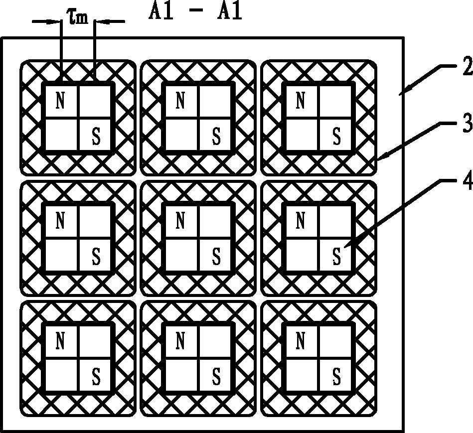
图1是具体实施方式一所述的一种磁通反向平面电机、当n=1时的结构示意图,图2是图1的A1-A1剖面图,图3是当n=2时,具体实施方式一所述的磁通反向平面电机中的一个初级齿1气隙侧的仰视图,图4是图1的B1-B1剖面图,图5是具体实施方式二所述的一种磁通凡平面电机、当n=1时的结构示意图,图6是图5的A2-A2剖面图,图7是当n=2时,具体实施方式二所述的磁通反向平面电机中的一个初级齿1气隙侧的仰视图,图9是具体实施方式三所述的磁通反向平面电机、当m=2时的结构示意图,图8是图9的C-C剖面图,图10是图8的D-D剖面图,图12是具体实施方式三所述的磁通反向平面电机、当m=3时的结构示意图,图11是图12的E-E剖面图,图13是图11的F-F剖面图,图14是具体实施方式三所述的磁通反向平面电机、当m=4时、一个初级齿1的气隙侧仰视图,图15是具体实施方式四所述的磁通反向平面电机的结构示意图,图16是图15的G-G剖面图,图17是具体实施方式四所述的磁通反向平面电机的结构示意图。图18和图19是现有平面电机的结构示意图。Fig. 1 is a kind of magnetic flux reversal planar motor described in
具体实施方式 Detailed ways
具体实施方式一、本实施方式所述的磁通反向平面电机由初级、次级和气隙构成,初级由一个或多个初级单元构成,每个初级单元包括初级单元铁心、初级绕组3和永磁体4;DETAILED DESCRIPTION OF THE
次级包括次级铁心5,在次级铁心5的气隙侧沿X向和沿Y向开有多个相互垂直的槽,使得次级铁心5的气隙侧表面形成矩阵型排布的次级齿,沿X向或沿Y向相邻的次级齿的中心之间的距离为次级齿的齿距τp;The secondary includes a
初级单元铁心2为平板形,在其面向气隙侧沿X向和沿Y向开有相互垂直的槽,使得所述初级单元铁心2的气隙侧表面形成矩阵型排布的初级齿1,每个初级齿1上绕有线圈,所有初级齿1上的线圈组成该初级单元的初级绕组3,The
每个初级齿1的面向气隙的齿表面均匀分成2n×2n个单元格,沿X向或沿Y向相邻两个单元格的中心距为τm,其中,n为自然数;在对角相邻的单元格中固定有一块永磁体4,并且位于每个初级齿1的面相气隙侧的表面上的所有永磁体4平行不相邻、垂直也不相邻;每块永磁体4为平行充磁,并且充磁方向垂直于初级齿1表面;The tooth surface facing the air gap of each
位于所有初级齿1的面向气隙侧齿表面的所有永磁体4中,位于同一行或列的永磁体4的充磁方向相同,位于相邻行或相邻列的永磁体4的充磁方向相反;Among all the
参数τm与τp之间满足关系2τm=τp。The relationship 2τ m =τ p is satisfied between the parameters τ m and τ p .
本实施方式中,次级铁心5上,气隙侧沿X向和沿Y向开有的槽数没有限定,因此,次级铁心5的大小,可以根据实际需要制作。In this embodiment, the number of slots on the
当本实施方式所述的平面电机为动初级结构时,次级铁心5的大小就是初级的运动范围,因此根据实际需要确定初级铁心的尺寸。When the planar motor described in this embodiment has a moving primary structure, the size of the
当本实施方式所述的平面电机为动次级结构时,初级将包括多个初级单元,根据次级的运动范围需求,将多个初级单元成矩阵型排列,进而扩大次级的运动范围。When the planar motor described in this embodiment has a moving secondary structure, the primary will include multiple primary units, and according to the motion range requirements of the secondary, the multiple primary units are arranged in a matrix to expand the secondary motion range.
当n=1时,本实施方式所述的平面电机的结构参见图1、2和3所示,将每个齿的面向气隙的齿表面均匀分成2×2个单元格;在第一行第一列的单元格内固定一块永磁体4,第二行第二列的单元格中固定一块永磁体4,所述两块永磁体4的充磁方向相反,沿X向或沿Y向每相邻两块永磁体4的中心距为τm,与沿X向和沿Y向次级齿的齿距τp之间满足关系2τm=τp。When n=1, the structure of the planar motor described in this embodiment is shown in Figures 1, 2 and 3, and the tooth surface facing the air gap of each tooth is evenly divided into 2×2 cells; in the first row A
本实施方式中的永磁体4的外形与单元格的形状相同。The shape of the
当n=2时,本实施方式所述的平面电机中的初级齿1的气隙侧仰视图参见图3所示,该初级齿1的表面均匀分成4×4个单元格,在第一行的第一列、第三列单元格内分别固定一块永磁体4,在第二行的第二列、第四列内分别嵌入一块永磁体4,在第三行的第一列、第三列单元格内分别固定一块永磁体4,在第四行的第二列、第四列内分别嵌入一块永磁体4,位于第一行和第三行的所有永磁体4的充磁方向相同,在第二行和第四行的所有永磁体4的充磁方向相同,并且与第一行的永磁体4的充磁方向相反。When n=2, the bottom view of the air gap side of the
具体实施方式二、本实施方式所述的磁通反向平面电机由初级、次级和气隙构成,初级由一个或多个初级单元构成,每个初级单元包括初级单元铁心、初级绕组3和永磁体4;
次级包括次级铁心5,在次级铁心5的气隙侧沿X向和沿Y向开有多个相互垂直的槽,使得次级铁心5的气隙侧表面形成矩阵型排布的次级齿,沿X向或沿Y向相邻的次级齿的中心之间的距离为次级齿的齿距τp;The secondary includes a
初级单元铁心2为平板形,在其面向气隙侧沿X向和沿Y向开有相互垂直的槽,使得所述初级单元铁心2的气隙侧表面形成矩阵型排布的次级初级齿1,每个初级齿1上绕有线圈,所有初级齿1上的线圈组成该初级单元的初级绕组3,The
每个初级齿1的面向气隙的齿表面均匀分成2n×2n个单元格,其中,n为自然数;所述单元格为边长是d1的正方形,沿X向每相邻的两个单元格之间嵌入一块永磁体4,所述永磁体4沿电机动子运动方向充磁,沿Y向每相邻的两个单元格之间嵌入一块永磁体4,所述永磁体4沿电机动子运动方向充磁,所述永磁体4为平板形永磁体4,该永磁体4在气隙侧端面为矩形,该矩形长d1、宽d2,该初级齿1内的极距τm=d1+d2;位于同一个的单元格周围的永磁体4对该单元格进行充磁,使其产生垂直初级齿1表面的磁场,定义该种单元格为充磁单元格41,位于同一初级齿1上的多个充磁单元格41对角相邻、且平行不相邻、垂直也不相邻,对角相邻的充磁单元格41的磁场方向相反,并且位于同一行或列的充磁单元格41的磁场方向相同;The tooth surface facing the air gap of each primary tooth 1 is evenly divided into 2n×2n cells, where n is a natural number; the cells are squares whose side length is d1, and every two adjacent cells along the X direction A permanent magnet 4 is embedded between them, and the permanent magnet 4 is magnetized along the moving direction of the motor mover, and a permanent magnet 4 is embedded between each adjacent two cells along the Y direction, and the permanent magnet 4 is magnetized along the motor mover Magnetization in the direction of motion, the permanent magnet 4 is a flat permanent magnet 4, the permanent magnet 4 is a rectangle on the side of the air gap, the rectangle has a length of d1 and a width of d2, and the pole pitch τ m in the primary tooth 1 = d1+ d2; The permanent magnet 4 located around the same cell magnetizes the cell so that it generates a magnetic field perpendicular to the surface of the primary tooth 1, defining this type of cell as a magnetized cell 41 located on the same primary tooth 1 A plurality of magnetized unit cells 41 are diagonally adjacent, not adjacent in parallel, nor vertically adjacent, the magnetic field directions of the diagonally adjacent magnetized unit cells 41 are opposite, and the magnetized units located in the same row or column The magnetic field direction of grid 41 is the same;
参数τm与τp之间满足关系2τm=τp。The relationship 2τ m =τ p is satisfied between the parameters τ m and τ p .
本实施方式中,次级铁心5上,气隙侧沿X向和沿Y向开有的槽数没有限定,因此,次级铁心5的大小,可以根据实际需要制作。In this embodiment, the number of slots on the
当本实施方式所述的平面电机为动初级结构时,次级铁心5的大小就是初级的运动范围,因此根据实际需要确定初级铁心的尺寸。When the planar motor described in this embodiment has a moving primary structure, the size of the
当本实施方式所述的平面电机为动次级结构时,初级将包括多个初级单元,根据次级的运动范围需求,将多个初级单元成矩阵型排列,进而扩大次级的运动范围。When the planar motor described in this embodiment has a moving secondary structure, the primary will include multiple primary units, and according to the motion range requirements of the secondary, the multiple primary units are arranged in a matrix to expand the secondary motion range.
当n=1时,本实施方式所述的平面电机的结构参见图5和6所示,将每个齿的面向气隙的齿表面均匀分成2×2个单元格;在第一行的两个单元格之间嵌入一块永磁体4,第二行的两个单元格之间嵌入一块永磁体4,第一列的两个单元格之间嵌入一块永磁体4,第二列的两个单元格之间嵌入一块永磁体4,其中,第一行第一列的单元格和第二行第二列的单元格是充磁单元格41,位于第一行第一列的充磁单元格41周围的永磁体4给该单元格充磁,使该单元格产生的磁场方向为垂直初级齿1表面并背离气隙侧,的充磁方向均是背向该单元格;位于第二行第二列的充磁单元格41周围的永磁体4给该单元格充磁,使该单元格产生的磁场方向为垂直与初级齿1表面,并指向气隙侧。When n=1, the structure of the planar motor described in this embodiment is shown in Figures 5 and 6, and the tooth surface facing the air gap of each tooth is evenly divided into 2×2 unit cells; A
当n=2时,本实施方式所述的平面电机中的初级齿1的气隙侧仰视图参见图7所示,该初级齿1的表面均匀分成4×4个单元格,其中,位于位于第一行的第一列和第三列单元格、位于第二行的第二列和第四列的单元格、位于第三行的第一列和第三列的单元格、位于第四行的第二列和第四列的单元格为充磁单元格41,其中是,位于第一行的第一列单元格周围的永磁体4为该单元格充磁,使该单元格覆盖下得初级齿1部分产生垂直于初级齿1表面的磁场,并且该磁场的方向为背向气隙侧,产生磁场方向与该单元格的磁场相同的还有位于第一行第三列单元格、位于第三行的第一列和第三列的单元格;位于第二行第二列的单元格周围的永磁体4为该单元格覆盖下得初级齿1部分充磁,使该单元格覆盖下得初级齿1部分产生垂直于初级齿1表面的磁场,并且该磁场方向为指向气隙侧,与该单元格产生的磁场方向相同的还有位于第二行第四列、位于第四行第二列和第四列的单元格。When n=2, the bottom view of the air gap side of the
具体实施方式三、本实施方式所述的磁通反向平面电机由初级、次级和气隙构成,初级由若干个初级单元构成,每个初级单元包括初级单元铁心、初级绕组3、永磁体4和导磁块6;Specific Embodiment Three. The magnetic flux reversal planar motor described in this embodiment is composed of a primary, a secondary and an air gap. The primary is composed of several primary units, and each primary unit includes a primary unit core, a primary winding 3, and a
次级包括次级铁心5,在次级铁心5的气隙侧沿X向和沿Y向开有相互垂直的槽,使得次级铁心5的气隙侧表面形成矩阵型排布的次级齿,沿X向或沿Y向相邻的次级齿的中心之间的距离为次级齿的齿距τp;The secondary includes a
初级单元铁心2为平板形,在其面向气隙侧沿X向和沿Y向开有相互垂直的槽,使得所述初级单元铁心2的气隙侧表面形成矩阵型排布的初级齿1,每个初级齿1上绕有线圈,所有初级齿1上的线圈组成该初级单元的初级绕组3;The
每个初级齿1的面向气隙的齿表面均匀分成m×m个单元格,沿X向或沿Y向相邻两个单元格的中心距为1/2τm,其中,m为大于1的自然数;在对角相邻的单元格中分别固定有一块永磁体4和一块导磁块6,并且位于每个初级齿1的面相气隙侧的表面上的所有永磁体4平行不相邻、垂直也不相邻,所有导磁块6平行不相邻、垂直也不相邻,导磁块6与永磁体4平行不相邻、垂直也不相邻;每块永磁体4为平行充磁,并且充磁方向垂直于初级齿1表面;位于初级齿1上的所有永磁体4的充磁方向相同;The tooth surface facing the air gap of each
参数τm与τp之间满足关系τm=τp。The parameter τ m and τ p satisfy the relationship τ m =τ p .
本实施方式中,次级铁心5上,气隙侧沿X向和沿Y向开有的槽数没有限定,因此,次级铁心5的大小,可以根据实际需要制作。In this embodiment, the number of slots on the
当本实施方式所述的平面电机为动初级结构时,次级铁心5的大小就是初级的运动范围,因此根据实际需要确定初级铁心的尺寸。When the planar motor described in this embodiment has a moving primary structure, the size of the
当本实施方式所述的平面电机为动次级结构时,初级将包括多个初级单元,根据次级的运动范围需求,将多个初级单元成矩阵型排列,进而扩大次级的运动范围。When the planar motor described in this embodiment has a moving secondary structure, the primary will include multiple primary units, and according to the motion range requirements of the secondary, the multiple primary units are arranged in a matrix to expand the secondary motion range.
本实施方式中的永磁体4的外形与单元格的形状相同,所述导磁块6的外形与永磁体4的外形相同。当m=2时,本实施方式所述的磁通反向平面电机的结构参见图8、9和10所示,每个初级齿1的面向气隙的齿表面均匀分成2×2个单元格;在第一行第一列的单元格内固定一块永磁体4,在第二行第二列的单元格内固定一块导磁块6,所述导磁块6可以与初级铁心为一体结构。The shape of the
当m=3时,本实施方式所述的磁通反向平面电机的结构参见图11、12和13所示,每个初级齿1的面向气隙的齿表面均匀分成3×3个单元格;在第一行的第一列和第三列的单元格内分别固定一块永磁体4,在第二行第二列的单元格内固定一块导磁块6,在第三行的第一列和第三列的单元格内分别固定一块永磁体4,所有永磁体4的充磁方向均相同,位于同一行的两块永磁体4的中心之间的距离为τm。When m=3, the structure of the magnetic flux reversal planar motor described in this embodiment is shown in Figures 11, 12 and 13, and the tooth surface facing the air gap of each
具体实施方式四、本实施方式是对具体实施方式一或所述的磁通反向平面电机的进一步限定,本实施方式所述的磁通反向平面电机的初级由多个初级单元组成,多个初级单元成矩阵型紧密排列,多个初级单元的铁心固定连接形成初级铁心,在所述初级铁心的每行初级齿1的两侧分别有一个端部齿,在每列的初级齿1的两侧分别有一个端部齿。
本实施方式在级铁心单元上增加了端部齿,所述端部齿用于给位于边缘的初级齿1提供磁通的路径,使每个初级齿1所形成的磁场都能够均匀分布。In this embodiment, end teeth are added to the primary core unit, and the end teeth are used to provide a magnetic flux path for the
所述的端部齿中,位于每行两端的端部齿的X向宽度小于初级齿1的X向宽度,位于每列两端的端部齿的Y向宽度小于初级齿1的Y向宽度。参见图15、16和17所示。Among the end teeth, the X-direction width of the end teeth located at both ends of each row is smaller than the X-direction width of the
Claims (9)
Priority Applications (1)
| Application Number | Priority Date | Filing Date | Title |
|---|---|---|---|
| CN 201110244432 CN102290961B (en) | 2011-08-25 | 2011-08-25 | Flux reverse planar motor |
Applications Claiming Priority (1)
| Application Number | Priority Date | Filing Date | Title |
|---|---|---|---|
| CN 201110244432 CN102290961B (en) | 2011-08-25 | 2011-08-25 | Flux reverse planar motor |
Publications (2)
| Publication Number | Publication Date |
|---|---|
| CN102290961A CN102290961A (en) | 2011-12-21 |
| CN102290961B true CN102290961B (en) | 2013-02-13 |
Family
ID=45337129
Family Applications (1)
| Application Number | Title | Priority Date | Filing Date |
|---|---|---|---|
| CN 201110244432 Expired - Fee Related CN102290961B (en) | 2011-08-25 | 2011-08-25 | Flux reverse planar motor |
Country Status (1)
| Country | Link |
|---|---|
| CN (1) | CN102290961B (en) |
Families Citing this family (1)
| Publication number | Priority date | Publication date | Assignee | Title |
|---|---|---|---|---|
| CN109921598B (en) * | 2019-03-22 | 2021-02-02 | 哈尔滨工业大学 | Magnetic flux reverse plane motor |
Citations (1)
| Publication number | Priority date | Publication date | Assignee | Title |
|---|---|---|---|---|
| CN101764497A (en) * | 2010-02-11 | 2010-06-30 | 哈尔滨工业大学 | Two-sided permanent magnet synchronous linear motor with integrated winding structure |
Family Cites Families (1)
| Publication number | Priority date | Publication date | Assignee | Title |
|---|---|---|---|---|
| WO2001080408A1 (en) * | 2000-04-19 | 2001-10-25 | Kabushiki Kaisha Yaskawa Denki | Permanent magnet synchronous linear motor |
-
2011
- 2011-08-25 CN CN 201110244432 patent/CN102290961B/en not_active Expired - Fee Related
Patent Citations (1)
| Publication number | Priority date | Publication date | Assignee | Title |
|---|---|---|---|---|
| CN101764497A (en) * | 2010-02-11 | 2010-06-30 | 哈尔滨工业大学 | Two-sided permanent magnet synchronous linear motor with integrated winding structure |
Also Published As
| Publication number | Publication date |
|---|---|
| CN102290961A (en) | 2011-12-21 |
Similar Documents
| Publication | Publication Date | Title |
|---|---|---|
| CN102594220B (en) | Magnetic suspension planar motor with superconductor excitation structure | |
| CN101610054B (en) | Planar motor adopting three-dimensional permanent magnet array | |
| CN102497083B (en) | Concentric permanent magnet synchronous planar motor with winding structure | |
| CN101710779A (en) | Long stroke synchronous planar motor with integrated winding structure | |
| CN209088784U (en) | A kind of ironless linear motors | |
| CN101741289B (en) | Short stroke multiple freedom degree magnetic levitation planar motor | |
| CN105356720B (en) | A kind of dual permanent-magnet transverse flux linear magneto | |
| CN102185443B (en) | Limited stroke high-dynamic plane motor | |
| CN101752983B (en) | Long-travel high-accuracy multiple-degree-of-freedom planar motor | |
| CN101610022B (en) | Planar motor adopting groove-type coil | |
| CN102299607B (en) | Transverse magnetic flux linear reluctance motor with offset permanent magnet | |
| CN101599677B (en) | Recombination current driven nine-phase plane motor, linear-rotating motor and driver thereof | |
| CN102290960A (en) | Cylindrical linear reluctance motor with permanent magnet offset structure | |
| CN101741212B (en) | Transverse flux permanent-magnet planar motor | |
| CN102255471B (en) | Linear switch magnetic flux permanent magnet motor with low location force and high thrust | |
| CN101800460B (en) | Short-stroke direct current planar motor integrating winding structure | |
| CN102739122B (en) | Magnetic suspension flat motor with primary structure on both sides | |
| CN102223052B (en) | Multi-DOF (degree of freedom) short-stroke planar motor | |
| CN108270337A (en) | A kind of switching magnetic-resistance two-dimensional surface motor | |
| CN102290961A (en) | Flux reverse planar motor | |
| CN109842264B (en) | A bilateral flat permanent magnet linear motor | |
| CN1284293C (en) | Permanent magnet magnetic resistance straight line motor | |
| CN202076918U (en) | Low positioning force high thrust linear switch magnetic flux permanent magnet motor | |
| CN109921598B (en) | Magnetic flux reverse plane motor | |
| CN101615826B (en) | Permanent magnet array of two-freedom motor with high power density |
Legal Events
| Date | Code | Title | Description |
|---|---|---|---|
| C06 | Publication | ||
| PB01 | Publication | ||
| C10 | Entry into substantive examination | ||
| SE01 | Entry into force of request for substantive examination | ||
| C14 | Grant of patent or utility model | ||
| GR01 | Patent grant | ||
| CF01 | Termination of patent right due to non-payment of annual fee |
Granted publication date: 20130213 |
|
| CF01 | Termination of patent right due to non-payment of annual fee |