EP1283354A2 - Fuel injection system - Google Patents
Fuel injection system Download PDFInfo
- Publication number
- EP1283354A2 EP1283354A2 EP02016623A EP02016623A EP1283354A2 EP 1283354 A2 EP1283354 A2 EP 1283354A2 EP 02016623 A EP02016623 A EP 02016623A EP 02016623 A EP02016623 A EP 02016623A EP 1283354 A2 EP1283354 A2 EP 1283354A2
- Authority
- EP
- European Patent Office
- Prior art keywords
- fuel
- solenoid valve
- fuel injection
- injector
- return
- Prior art date
- Legal status (The legal status is an assumption and is not a legal conclusion. Google has not performed a legal analysis and makes no representation as to the accuracy of the status listed.)
- Withdrawn
Links
Images

Classifications
-
- F—MECHANICAL ENGINEERING; LIGHTING; HEATING; WEAPONS; BLASTING
- F02—COMBUSTION ENGINES; HOT-GAS OR COMBUSTION-PRODUCT ENGINE PLANTS
- F02M—SUPPLYING COMBUSTION ENGINES IN GENERAL WITH COMBUSTIBLE MIXTURES OR CONSTITUENTS THEREOF
- F02M61/00—Fuel-injectors not provided for in groups F02M39/00 - F02M57/00 or F02M67/00
- F02M61/16—Details not provided for in, or of interest apart from, the apparatus of groups F02M61/02 - F02M61/14
- F02M61/168—Assembling; Disassembling; Manufacturing; Adjusting
-
- F—MECHANICAL ENGINEERING; LIGHTING; HEATING; WEAPONS; BLASTING
- F02—COMBUSTION ENGINES; HOT-GAS OR COMBUSTION-PRODUCT ENGINE PLANTS
- F02M—SUPPLYING COMBUSTION ENGINES IN GENERAL WITH COMBUSTIBLE MIXTURES OR CONSTITUENTS THEREOF
- F02M47/00—Fuel-injection apparatus operated cyclically with fuel-injection valves actuated by fluid pressure
- F02M47/02—Fuel-injection apparatus operated cyclically with fuel-injection valves actuated by fluid pressure of accumulator-injector type, i.e. having fuel pressure of accumulator tending to open, and fuel pressure in other chamber tending to close, injection valves and having means for periodically releasing that closing pressure
- F02M47/027—Electrically actuated valves draining the chamber to release the closing pressure
-
- F—MECHANICAL ENGINEERING; LIGHTING; HEATING; WEAPONS; BLASTING
- F02—COMBUSTION ENGINES; HOT-GAS OR COMBUSTION-PRODUCT ENGINE PLANTS
- F02M—SUPPLYING COMBUSTION ENGINES IN GENERAL WITH COMBUSTIBLE MIXTURES OR CONSTITUENTS THEREOF
- F02M55/00—Fuel-injection apparatus characterised by their fuel conduits or their venting means; Arrangements of conduits between fuel tank and pump F02M37/00
- F02M55/002—Arrangement of leakage or drain conduits in or from injectors
-
- F—MECHANICAL ENGINEERING; LIGHTING; HEATING; WEAPONS; BLASTING
- F02—COMBUSTION ENGINES; HOT-GAS OR COMBUSTION-PRODUCT ENGINE PLANTS
- F02M—SUPPLYING COMBUSTION ENGINES IN GENERAL WITH COMBUSTIBLE MIXTURES OR CONSTITUENTS THEREOF
- F02M55/00—Fuel-injection apparatus characterised by their fuel conduits or their venting means; Arrangements of conduits between fuel tank and pump F02M37/00
- F02M55/004—Joints; Sealings
- F02M55/005—Joints; Sealings for high pressure conduits, e.g. connected to pump outlet or to injector inlet
-
- F—MECHANICAL ENGINEERING; LIGHTING; HEATING; WEAPONS; BLASTING
- F02—COMBUSTION ENGINES; HOT-GAS OR COMBUSTION-PRODUCT ENGINE PLANTS
- F02M—SUPPLYING COMBUSTION ENGINES IN GENERAL WITH COMBUSTIBLE MIXTURES OR CONSTITUENTS THEREOF
- F02M55/00—Fuel-injection apparatus characterised by their fuel conduits or their venting means; Arrangements of conduits between fuel tank and pump F02M37/00
- F02M55/007—Venting means
-
- F—MECHANICAL ENGINEERING; LIGHTING; HEATING; WEAPONS; BLASTING
- F02—COMBUSTION ENGINES; HOT-GAS OR COMBUSTION-PRODUCT ENGINE PLANTS
- F02M—SUPPLYING COMBUSTION ENGINES IN GENERAL WITH COMBUSTIBLE MIXTURES OR CONSTITUENTS THEREOF
- F02M2547/00—Special features for fuel-injection valves actuated by fluid pressure
- F02M2547/003—Valve inserts containing control chamber and valve piston
Definitions
- the invention relates to a fuel injection device with an injector and a solenoid valve to control the injection process.
- a solenoid valve to control the injection process.
- Solenoid valve control solenoid
- the installation space i.e. 90 ° to the injector, flanged to the injector housing.
- Venting the armature space of the solenoid valve presents problems.
- Known fuel injection device is proposed on a End of the solenoid valve facing away from the injector provided. This can lead to installation space problems. Finds an insufficient one Venting, d. H. formation of air bubbles in the anchor space occurs a lack of damping in the absence of fuel. The anchor tilts in such cases to vibrations.
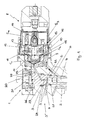
- FIG. 1 shows the structure of part of a fuel injection device 1 is visible.
- the general structure of such a fuel injection device 1 is known and is described, for example, in EP 0 907 018 A2. Therefore, Fig. 1 shows only the upper part.
- a pressure line 2 in a housing 3 of an injector 3 'of the fuel injection device 1 leads to high-pressure fuel to a nozzle space, not shown in FIG. 1.
- a push rod 4 bears against a nozzle needle, also not shown, in such a way that it can be moved from an open position to a closed position or vice versa.
- the movement of the nozzle needle is controlled via the pressure ratio in a control space 5 to the nozzle space, since the control space 5 in a valve piece 6 is also filled with fuel under high pressure via a pressure line 7 .
- the control room 5 can be relieved of pressure to carry out the fuel injection by continuously connecting the control room 5 to a return bore, which is connected to a fuel tank, by means of a solenoid valve 8 arranged at a 90 ° angle to the push rod.
- the solenoid valve 8 closes an opening in a valve plate 9 via a pressurizable ball 10 .
- the solenoid valve 8 which is known in its functional design, further comprises an armature guide 11 , an armature pin 12 , an armature plate 13 , a valve spring 14 and an armature plate spring 15 . If the anchor bolt 15 is pulled back when the solenoid valve 8 flows against it (open valve position), the pressure relief of the control room 5 is initiated. This results in the bold or dotted flow guidance within the solenoid valve 8. Air bubble formation in an armature space 16 of the solenoid valve 8 is avoided because the flow guidance entrains air bubbles and leads out of the solenoid valve 8 to the outside.
- a leakage line 17 for returning fuel from a pressure rod chamber when the nozzle needle is open is connected to a lower flow channel 18 , so that a leakage quantity from the pressure rod region and a control quantity of fuel from the control region are combined at this point.
- the air bubbles are first forced into an upper flow channel 19 and then into the return bore and thus out of the solenoid valve 8. Fuel is diverted in the solenoid valve 8 and led out again. A flow guidance over flow channels is formed, which avoids a backflow.
- the input channel is divided into two flow paths S 1 and S 2 in order to lead fuel up to the valve spring 14, preferably to unite there, then again in opposite directions on two further flow paths S 3 and Lead out S 4 in the direction of the inlet channel (valve plate 9) and feed it to the fuel tank again (fuel return indicated by dots).
- the arrangement of the seals 20, 21, 23, 25 takes into account the pressures applied to the seals 20, 21, 23, 25.
- Hard metallic seals are proposed for high pressures. Teflon® seals are suggested for seals that are exposed to lower pressures or that have less of a leakage effect.
- the control room 5 is limited at the top by a hard seal.
- the seal 23 is pressed upward by the pressure acting on the seal 23, as a result of which the control space 5 is kept as minimal as possible. Via the support ring 24 and the shape of the space around the seal 23, the seal 23 is brought into a defined axial position. Since the pressure difference between the ring channel 22 and the control room 5 is smaller than the pressure difference between the control room 5 and the housing 3, the use of the sealing material Teflon® is justified.
- a radial fixation between the housing 3 and the valve piece 6 is carried out by means of a metallic pin 26 according to FIG. 2 .
- a semicircular bore 27, 28 is provided, in the space between which the pin 26 is pressed and thus provides a clear assignment.
- the arrangement of the fixation on a large diameter makes the assignment insensitive to tolerances.
- the lugs 30 protrude into the housing 3 and thus prevent the disk 27 from rotating when a locking screw 31 is tightened. A rotation of the valve piece 6 when tightening the screw plug 29 is thus excluded.
Abstract
Description
Die Erfindung betrifft eine Kraftstoffeinspritzeinrichtung mit einem Injektor und mit einem Magnetventil zur Steuerung des Einspritzvorgangs. Vorzugsweise ist das Magnetventil (Stellmagnet) aus durch den Bauraum bedingten Gründen quer, d.h. 90° zum Injektor, am Injektorgehäuse angeflanscht.The invention relates to a fuel injection device with an injector and a solenoid valve to control the injection process. Preferably that is Solenoid valve (control solenoid) for reasons related to the installation space, i.e. 90 ° to the injector, flanged to the injector housing.
Eine derartige Kraftstoffeinspritzeinrichtung ist beispielsweise durch die EP 0 907 018 A2 bekannt geworden.Such a fuel injection device is described, for example, by EP 0 907 018 A2 became known.
Probleme bereitet die Entlüftung des Ankerraums des Magnetventils. Bei der bekannten Kraftstoffeinspritzeinrichtung wird vorgeschlagen, an einem dem Injektor abgewandten Ende des Magnetventils einen Kraftstoffrücklauf vorzusehen. Dies kann zu Bauraumproblemen führen. Findet eine unzureichende Entlüftung, d. h. eine Bildung von Luftblasen im Ankerraum statt, kommt es zu einer mangelnden Dämpfung bei fehlendem Kraftstoff. Der Anker neigt in derartigen Fällen zu Schwingungen.Venting the armature space of the solenoid valve presents problems. In the Known fuel injection device is proposed on a End of the solenoid valve facing away from the injector provided. This can lead to installation space problems. Finds an insufficient one Venting, d. H. formation of air bubbles in the anchor space occurs a lack of damping in the absence of fuel. The anchor tilts in such cases to vibrations.
Zur Vermeidung dieser Probleme wird eine Kraftstoffeinspritzung gemäß Patentanspruch 1 vorgeschlagen. Durch die Strömungsführung im Magnetventil wird innerhalb der Randbedingungen eine Entlüftung des Ankerraums des Magnetventils, d. h. ein möglichst vollständig nur mit Kraftstoff gefüllter Ankerraum, gewährleistet. Damit verbunden ist eine ausreichende Ankerdämpfung und demzufolge eine gute Injektordynamik und insbesondere eine Realisierung eines geringen Abstands zwischen der Vor- und Haupteinspritzung. Als Folge davon reduziert sich überdies die Rücklaufmenge. To avoid these problems, fuel injection is performed according to Claim 1 proposed. Through the flow in the solenoid valve If the anchor space is vented within the boundary conditions Solenoid valve, d. H. one that is as completely filled with fuel as possible Anchor room, guaranteed. Adequate anchor damping is associated with this and consequently good injector dynamics and in particular a realization a small distance between the pre and main injection. As a result this also reduces the return volume.
Ein Ausführungsbeispiel der Erfindung wird anhand schematischer Darstellungen näher erläutert. Es zeigt:
- Fig. 1
- einen Teil einer Kraftstoffeinspritzeinrichtung mit einem Magnetventil zur Steuerung der Kraftstoffeinspritzung im Längsschnitt;
- Fig. 2
- einen vergrößerten Ausschnitt eines Querschnitts entlang der Linie II-II in Fig. 1;
- Fig. 3
- einen vergrößerten Ausschnitt eines Querschnitts entlang der Linie III-III in Fig. 1.
- Fig. 1
- part of a fuel injection device with a solenoid valve for controlling the fuel injection in longitudinal section;
- Fig. 2
- an enlarged section of a cross section along the line II-II in Fig. 1;
- Fig. 3
- an enlarged section of a cross section along the line III-III in Fig. 1st
Aus der Fig. 1 ist der Aufbau eines Teils einer Kraftstoffeinspritzeinrichtung 1
ersichtlich. Der allgemeine Aufbau einer derartigen Kraftstoffeinspritzeinrichtung 1
ist bekannt und beispielsweise in der EP 0 907 018 A2 beschrieben. Daher zeigt
Fig. 1 nur den oberen Teil. Eine Druckleitung 2 in einem Gehäuse 3 eines Injektors
3' der Kraftstoffeinspritzeinrichtung 1 führt unter Hochdruck stehenden Kraftstoff
zu einem in der Fig. 1 nicht dargestellten Düsenraum. Eine Druckstange 4 liegt an
einer ebenfalls nicht dargestellten Düsennadel derart an, dass diese von einer
Offenstellung in eine Schließstellung bzw. umgekehrt bewegt werden kann. Die
Bewegung der Düsennadel wird über das Druckverhältnis in einem Kontrollraum 5
zu dem Düsenraum gesteuert, da der Kontrollraum 5 in einem Ventilstück 6 über
eine Druckleitung 7 ebenfalls mit unter Hochdruck stehendem Kraftstoff befüllt
wird. Der Kontrollraum 5 kann zur Durchführung der Kraftstoffeinspritzung
druckentlastet werden, indem der Kontrollraum 5 mit Hilfe eines unter einem 90°
Winkel zur Druckstange angeordneten Magnetventils 8 an eine Rücklaufbohrung
durchgängig angeschlossen wird, die mit einem Kraftstofftank in Verbindung
steht. Das Magnetventil 8 verschließt eine Öffnung in einer Ventilplatte 9 über
eine druckbeaufschlagbare Kugel 10. Das in seinem funktionalen Aufbau bekannte
Magnetventil 8 umfasst weiterhin eine Ankerführung 11, einen Ankerbolzen 12,
eine Ankerplatte 13, eine Ventilfeder 14 und eine Ankerplattenfeder 15. Wird der
Ankerbolzen 15 bei Anströmung des Magnetventils 8 zurückgezogen (geöffnete
Ventilstellung), so wird die Druckentlastung des Kontrollraum 5 eingeleitet. Dabei
kommt es zu der fett bzw. gepunktet eingezeichneten Strömungsführung
innerhalb des Magnetventils 8. Eine Luftblasenbildung in einem Ankerraum 16 des
Magnetventils 8 wird vermieden, weil die Strömungsführung Luftblasen mitreißt
und aus dem Magnetventil 8 nach außen führt. Eine Leckageleitung 17 zur
Rückführung von Kraftstoff aus einem Druckstangenraum bei Offenstellung der
Düsennadel ist mit einem unteren Strömungskanal 18 verbunden, so dass an
dieser Stelle eine Vereinigung einer Leckagemenge aus dem Druckstangenbereich
und einer Steuermenge an Kraftstoff aus dem Kontrollbereich stattfindet. Die
Luftblasen werden zunächst in einen oberen Strömungskanal 19 und anschließend
in die Rücklaufbohrung und somit aus dem Magnetventil 8 gedrängt. Kraftstoff
wird im Magnetventil 8 umgeleitet und wieder heraus geführt. Es wird eine
Strömungsführung über Strömungskanäle ausgebildet, die einen Rückstau
vermeidet. Nach dem Eintritt von Kraftstoff aus dem Kontrollraum 5 in das
Magnetventil 8 wird der Eingangskanal in zwei Strömungspfade S 1 und S 2
aufgeteilt, um Kraftstoff bis zur Ventilfeder 14 zu führen, dort vorzugsweise zu
vereinigen, anschließend wieder gegenläufig auf zwei weiteren Strömungspfaden
S 3 und S 4 in Richtung Eingangskanal (Ventilplatte 9) herauszuführen und dem
Kraftstofftank erneut zuzuführen (Kraftstoffrückführung gepunktet angedeutet).From Fig. 1 shows the structure of part of a fuel injection device 1 is visible. The general structure of such a fuel injection device 1 is known and is described, for example, in EP 0 907 018 A2. Therefore, Fig. 1 shows only the upper part. A
Zur Abdichtung der Anordnung werden eine harte metallische Dichtung 20 zur
Abdichtung zwischen dem Gehäuse 3 und dem Ventilstück 6, eine
Hochdruckdichtung 21 aus Teflon® zur Abdichtung zwischen dem
Druckstangenraum und einem Ringkanal 22, eine Hochdruckabdichtung 23 aus
Teflon® im Zusammenwirken mit einem Stützring 24 zur Abdichtung zwischen
dem Kontrollraum 5 und dem Ringkanal 22 und schließlich eine harte metallische
Hochdruckdichtung 25 zur Abdichtung zwischen dem Kontrollraum 5 und dem
Magnetventil 8 verwendet. Die Anordnung der Dichtungen 20, 21, 23, 25
berücksichtigt die an den Dichtungen 20, 21, 23, 25 anliegenden Drücke. Für
große Drücke werden harte metallische Dichtungen vorgeschlagen. Bei
Dichtungen, die kleineren Drücken ausgesetzt sind oder bei denen eine geringere
Auswirkung einer Undichtheit auftritt, werden Teflon® dichtungen vorgeschlagen.
Der Kontrollraum 5 ist nach oben durch eine harte Abdichtung begrenzt. Die
Dichtung 23 wird durch den auf die Dichtung 23 wirkenden Druck nach oben
gedrückt, wodurch der Kontrollraum 5 möglichst minimal gehalten wird. Über den
Stützring 24 und die Formgebung des Raumes um die Dichtung 23 wird die
Dichtung 23 in eine definierte axiale Lage gebracht. Da die Druckdifferenz
zwischen Ringkanal 22 und Kontrollraum 5 kleiner ist als die Druckdifferenz
zwischen Kontrollraum 5 und Gehäuse 3 rechtfertigt sich die Verwendung des
Dichtmaterials Teflon®.To seal the arrangement, a hard
Um eine gezielte radiale Montage des Ventilstücks 6 zu gewährleisten, da sich die
Verbindungsbohrungen treffen müssen, wird mittels eines metallischen Stiftes 26
gemäß Fig. 2 eine radiale Fixierung zwischen dem Gehäuse 3 und dem Ventilstück
6 vorgenommen. Sowohl im Gehäuse 3 als auch im Ventilstück 6 ist eine
halbkreisförmige Bohrung 27, 28 vorgesehen, in deren Zwischenraum der Stift 26
eingedrückt wird und so eine klare Zuordnung vorgibt. Durch die Anordnung der
Fixierung auf großem Durchmesser ist die Zuordnung toleranzunempfindlich. Über
dem Verbindungsstück 6 liegt eine Scheibe 29 mit zwei Nasen 30 gemäß Fig. 3,
von denen in dem Ausschnitt der Fig. 3 nur eine dargestellt ist. Die Nasen 30
ragen in das Gehäuse 3 hinein und verhindern somit ein Verdrehen der Scheibe 27
beim Anziehen einer Verschlussschraube 31. Ein Verdrehen des Ventilstücks 6
beim Anziehen der Verschlussschraube 29 ist damit ausgeschlossen. In order to ensure a targeted radial assembly of the
- 11
- KraftstoffeinspritzeinrichtungFuel injection system
- 22
- Druckleitungpressure line
- 33
- Gehäusecasing
- 3'3 '
- Injektorinjector
- 44
- Druckstangepushrod
- 55
- Kontrollraumcontrol room
- 66
- Ventilstückvalve piece
- 77
- Druckleitungpressure line
- 88th
- Magnetventilmagnetic valve
- 99
- Ventilplattevalve plate
- 1010
- KugelBullet
- 1111
- Ankerführungarmature guide
- 1 21 2
- Ankerbolzenanchor bolts
- 1313
- Ankerplatteanchor plate
- 1414
- Ventilfedervalve spring
- 1 51 5
- AnkerplattenfederAnchor plate spring
- 1616
- Ankerraumarmature space
- 1717
- Leckageleitungleakage line
- 1818
- Unterer StrömungskanalLower flow channel
- 1919
- Oberer StrömungskanalUpper flow channel
- 2020
- Dichtungpoetry
- 2121
- Dichtungpoetry
- 2222
- Ringkanalannular channel
- 2323
- Dichtungpoetry
- 2424
- Stützringsupport ring
- 2525
- Dichtungpoetry
- 2626
- Stiftpen
- 2727
- Bohrungdrilling
- 2828
- Bohrungdrilling
- 2929
- Scheibe disc
- 3030
- Nasenose
- 3131
- VerschlussschraubeScrew
- S1 S 1
- Strömungspfadflow path
- S2 S 2
- Strömungspfadflow path
- S3 S 3
- Strömungspfadflow path
- S4 S 4
- Strömungspfadflow path
Claims (5)
Applications Claiming Priority (2)
| Application Number | Priority Date | Filing Date | Title |
|---|---|---|---|
| DE2001139680 DE10139680A1 (en) | 2001-08-11 | 2001-08-11 | Fuel injection system |
| DE10139680 | 2001-08-11 |
Publications (2)
| Publication Number | Publication Date |
|---|---|
| EP1283354A2 true EP1283354A2 (en) | 2003-02-12 |
| EP1283354A3 EP1283354A3 (en) | 2003-11-26 |
Family
ID=7695277
Family Applications (1)
| Application Number | Title | Priority Date | Filing Date |
|---|---|---|---|
| EP02016623A Withdrawn EP1283354A3 (en) | 2001-08-11 | 2002-07-25 | Fuel injection system |
Country Status (3)
| Country | Link |
|---|---|
| EP (1) | EP1283354A3 (en) |
| JP (1) | JP2003113762A (en) |
| DE (1) | DE10139680A1 (en) |
Citations (1)
| Publication number | Priority date | Publication date | Assignee | Title |
|---|---|---|---|---|
| EP0907018A2 (en) | 1997-10-02 | 1999-04-07 | ELASIS SISTEMA RICERCA FIAT NEL MEZZOGIORNO Società Consortile per Azioni | Electromagnetic fuel injector for internal combustion engines |
Family Cites Families (6)
| Publication number | Priority date | Publication date | Assignee | Title |
|---|---|---|---|---|
| US4605166A (en) * | 1985-02-21 | 1986-08-12 | Stanadyne, Inc. | Accumulator injector |
| DE59310268D1 (en) * | 1992-12-23 | 2002-04-11 | Ganser Hydromag Ag Zuerich | Fuel injector |
| DE19616812B4 (en) * | 1995-04-27 | 2004-09-30 | Nippon Soken, Inc., Nishio | Fuel injector |
| JP3446432B2 (en) * | 1995-12-05 | 2003-09-16 | 株式会社デンソー | Fuel injection device |
| EP0844385B1 (en) * | 1996-11-21 | 2003-03-05 | Denso Corporation | Accumulator fuel injection apparatus for internal combustion engine |
| DE19917190A1 (en) * | 1999-04-16 | 2000-10-26 | Mtu Friedrichshafen Gmbh | Fuel injector for internal combustion engine; has high pressure channel to supply fuel and nozzle needle in guide bore and has high pressure space behind guide bore to receive overflowing fuel |
-
2001
- 2001-08-11 DE DE2001139680 patent/DE10139680A1/en not_active Withdrawn
-
2002
- 2002-07-25 EP EP02016623A patent/EP1283354A3/en not_active Withdrawn
- 2002-08-08 JP JP2002231879A patent/JP2003113762A/en not_active Abandoned
Patent Citations (1)
| Publication number | Priority date | Publication date | Assignee | Title |
|---|---|---|---|---|
| EP0907018A2 (en) | 1997-10-02 | 1999-04-07 | ELASIS SISTEMA RICERCA FIAT NEL MEZZOGIORNO Società Consortile per Azioni | Electromagnetic fuel injector for internal combustion engines |
Also Published As
| Publication number | Publication date |
|---|---|
| EP1283354A3 (en) | 2003-11-26 |
| JP2003113762A (en) | 2003-04-18 |
| DE10139680A1 (en) | 2003-02-27 |
Similar Documents
| Publication | Publication Date | Title |
|---|---|---|
| DE602005000662T2 (en) | Injection valve of an internal combustion engine | |
| EP0302068B1 (en) | Check valve | |
| DE4442085C2 (en) | Electromagnetically operated proportional pressure control valve | |
| DE3102642A1 (en) | ELECTROMAGNETIC FUEL INJECTION VALVE | |
| EP1700058B1 (en) | Valve for controlling a fluid | |
| EP0615064B1 (en) | Injection valve control system for internal combustion engines | |
| DE10016242A1 (en) | Pressure control valve with integrated safety function e.g. for motor vehicle | |
| EP1407134B1 (en) | High-pressure fuel device | |
| DE2439842A1 (en) | THROTTLE VALVE | |
| EP1043496B1 (en) | Injector for fuel injection in an internal combustion engine | |
| EP1283354A2 (en) | Fuel injection system | |
| EP4174358A1 (en) | Pressure vessel having multiple lateral outflow apertures | |
| DE19937677C2 (en) | Injector with improved sealing surface arrangement | |
| DE202021105982U1 (en) | pressure vessel | |
| EP4288654A1 (en) | Injector for blowing a gas into a combustion chamber or into an intake manifold of a motor vehicle | |
| DE10216622B3 (en) | One-piece control module for a fuel injector | |
| EP1961949B1 (en) | Injector with additional servo-valve | |
| DE102005023179B3 (en) | Injection valve for common rail fuel injection system has drain chamber connected to leakage drilling via restrictor which creates back-pressure to reduce flow of fuel via sealing gaps into drain chamber | |
| DE10050599B4 (en) | Injection valve with a pump piston | |
| DE1193325B (en) | Adjustable injection valve | |
| DE102004010759A1 (en) | Common rail injector | |
| DE10121340A1 (en) | Common rail injector for internal combustion engine fuel injection system has casing and intermediate plate bounding control chamber implemented in one piece with inlet and outlet choke | |
| DE19960065B4 (en) | Steam forming valve in straight form | |
| DE3117018A1 (en) | FUEL INJECTION NOZZLE | |
| DE102016221543A1 (en) | Fuel injection valve for injecting a gaseous and / or liquid fuel |
Legal Events
| Date | Code | Title | Description |
|---|---|---|---|
| PUAI | Public reference made under article 153(3) epc to a published international application that has entered the european phase |
Free format text: ORIGINAL CODE: 0009012 |
|
| AK | Designated contracting states |
Designated state(s): AT BE BG CH CY CZ DE DK EE ES FI FR GB GR IE IT LI LU MC NL PT SE SK TR |
|
| AX | Request for extension of the european patent |
Extension state: AL LT LV MK RO SI |
|
| PUAL | Search report despatched |
Free format text: ORIGINAL CODE: 0009013 |
|
| AK | Designated contracting states |
Kind code of ref document: A3 Designated state(s): AT BE BG CH CY CZ DE DK EE ES FI FR GB GR IE IT LI LU MC NL PT SE SK TR |
|
| AX | Request for extension of the european patent |
Extension state: AL LT LV MK RO SI |
|
| 17P | Request for examination filed |
Effective date: 20040526 |
|
| AKX | Designation fees paid |
Designated state(s): DE FR GB IT |
|
| 17Q | First examination report despatched |
Effective date: 20040917 |
|
| STAA | Information on the status of an ep patent application or granted ep patent |
Free format text: STATUS: THE APPLICATION IS DEEMED TO BE WITHDRAWN |
|
| 18D | Application deemed to be withdrawn |
Effective date: 20041218 |