EP1283081A2 - Umformung, insbesondere zur Innenhochdruckformung - Google Patents
Umformung, insbesondere zur Innenhochdruckformung Download PDFInfo
- Publication number
- EP1283081A2 EP1283081A2 EP02015272A EP02015272A EP1283081A2 EP 1283081 A2 EP1283081 A2 EP 1283081A2 EP 02015272 A EP02015272 A EP 02015272A EP 02015272 A EP02015272 A EP 02015272A EP 1283081 A2 EP1283081 A2 EP 1283081A2
- Authority
- EP
- European Patent Office
- Prior art keywords
- pressure
- forming
- forming tool
- tool
- workpiece
- Prior art date
- Legal status (The legal status is an assumption and is not a legal conclusion. Google has not performed a legal analysis and makes no representation as to the accuracy of the status listed.)
- Withdrawn
Links
Images

Classifications
-
- B—PERFORMING OPERATIONS; TRANSPORTING
- B21—MECHANICAL METAL-WORKING WITHOUT ESSENTIALLY REMOVING MATERIAL; PUNCHING METAL
- B21D—WORKING OR PROCESSING OF SHEET METAL OR METAL TUBES, RODS OR PROFILES WITHOUT ESSENTIALLY REMOVING MATERIAL; PUNCHING METAL
- B21D26/00—Shaping without cutting otherwise than using rigid devices or tools or yieldable or resilient pads, i.e. applying fluid pressure or magnetic forces
- B21D26/02—Shaping without cutting otherwise than using rigid devices or tools or yieldable or resilient pads, i.e. applying fluid pressure or magnetic forces by applying fluid pressure
- B21D26/033—Deforming tubular bodies
- B21D26/047—Mould construction
-
- B—PERFORMING OPERATIONS; TRANSPORTING
- B21—MECHANICAL METAL-WORKING WITHOUT ESSENTIALLY REMOVING MATERIAL; PUNCHING METAL
- B21D—WORKING OR PROCESSING OF SHEET METAL OR METAL TUBES, RODS OR PROFILES WITHOUT ESSENTIALLY REMOVING MATERIAL; PUNCHING METAL
- B21D26/00—Shaping without cutting otherwise than using rigid devices or tools or yieldable or resilient pads, i.e. applying fluid pressure or magnetic forces
- B21D26/02—Shaping without cutting otherwise than using rigid devices or tools or yieldable or resilient pads, i.e. applying fluid pressure or magnetic forces by applying fluid pressure
- B21D26/021—Deforming sheet bodies
- B21D26/025—Means for controlling the clamping or opening of the moulds
-
- B—PERFORMING OPERATIONS; TRANSPORTING
- B21—MECHANICAL METAL-WORKING WITHOUT ESSENTIALLY REMOVING MATERIAL; PUNCHING METAL
- B21D—WORKING OR PROCESSING OF SHEET METAL OR METAL TUBES, RODS OR PROFILES WITHOUT ESSENTIALLY REMOVING MATERIAL; PUNCHING METAL
- B21D26/00—Shaping without cutting otherwise than using rigid devices or tools or yieldable or resilient pads, i.e. applying fluid pressure or magnetic forces
- B21D26/02—Shaping without cutting otherwise than using rigid devices or tools or yieldable or resilient pads, i.e. applying fluid pressure or magnetic forces by applying fluid pressure
- B21D26/021—Deforming sheet bodies
- B21D26/031—Mould construction
-
- B—PERFORMING OPERATIONS; TRANSPORTING
- B21—MECHANICAL METAL-WORKING WITHOUT ESSENTIALLY REMOVING MATERIAL; PUNCHING METAL
- B21D—WORKING OR PROCESSING OF SHEET METAL OR METAL TUBES, RODS OR PROFILES WITHOUT ESSENTIALLY REMOVING MATERIAL; PUNCHING METAL
- B21D26/00—Shaping without cutting otherwise than using rigid devices or tools or yieldable or resilient pads, i.e. applying fluid pressure or magnetic forces
- B21D26/02—Shaping without cutting otherwise than using rigid devices or tools or yieldable or resilient pads, i.e. applying fluid pressure or magnetic forces by applying fluid pressure
- B21D26/033—Deforming tubular bodies
- B21D26/039—Means for controlling the clamping or opening of the moulds
Definitions
- the present invention relates to a forming device according to the preamble of claim 1.
- DE 197 15 593 C2 discloses an internal high-pressure forming device for Forming of hollow workpiece blanks.
- the shaping device has a die system into which the workpiece blank to be formed is introduced becomes.
- a forming liquid line is connected to the die system, via which pressure is applied to the workpiece blank from the inside the tool, i.e. recorded by the matrix system must become.
- the internal pressure is deformed Workpiece blank according to the inner contour of the die system, whereby the air trapped between the workpiece blank and the die escapes from the die system via a vent hole.
- the object of the invention is therefore to provide a forming device with that even small numbers of workpieces can be produced economically.
- the basic principle of the invention is that of the inside of the forming tool acting pressure forces, i.e. the "forming pressure” at least partially compensated by “counter or stabilizing pressure”, that acts on the tool from the outside.
- the forming tool is arranged in a "pressure chamber".
- the Forming tool or a "cavity" in the forming tool introduced workpiece blank is via a pressure medium line with a Pressure medium connection connected via which the forming pressure is applied becomes.
- To apply a "back pressure” from the outside to the Forming tool is provided so that the pressure chamber has a “pressure input” has, which also via the pressure medium connection of the Forming tool can be acted upon.
- the pressure medium connection of the Forming tool via a control valve with the pressure inlet of the pressure chamber connected.
- the control valve enables precise control of the counter- or external forces acting on the forming tool "Compensation pressure".
- a ventilation line is provided, which is led out of the forming tool and the one Venting the between the tool blank and the forming tool trapped air to the atmosphere.
- a further control valve through which the pressure prevailing between the tool and the workpiece blank is.
- An electronic control device is used to control the control valves provided that applied to the workpiece blank from the inside Forming pressure between the workpiece blank and the forming tool prevailing pressure as well as the prevailing in the pressure room counter- or compensation pressure acting on the forming tool from the outside regulates.
- the control device preferably controls the Control valves so that by the above pressures mechanical stress on the forming tool is minimal.
- the pressure chamber has an opening or closing device, e.g. B. a cover through which the forming tool is introduced into the pressure chamber can be.
- the pressure room thus represents a "basic machine” that is independent from the forming tool. That is, depending on the application different forming tools are placed in the printing room.
- the pressure space limited by an outer container and a "lid" can be arranged sunk in the ground, for example. This has the The advantage that the pressure chamber is stabilized by the external pressure of the soil becomes.
- the pressure chamber can also be an above-ground one Be machine component, which is designed accordingly massive.
- the outer geometry of the forming tool can be used for better pressure absorption be matched to the workpiece geometry. For example thanks to a spherical outer geometry, significantly better pressure introduction can be achieved than by a cuboid tool geometry.
- the above-mentioned pressure levels can be adjusted by the respective control valves Process can be optimally adapted. Determine the pressure levels on the one hand, the forming process directly, on the other hand, through a targeted control of the pressure levels of the tool to be controlled.
- a major advantage is that through appropriate Regulation of the pressure levels the tool can be designed weaker can. For example, a small one at the beginning of the forming process Counter or external pressure can be set to the load of the To minimize the "outer shell" of the forming tool.
- the forming device according to the invention is for different workpiece materials usable, such as steel, light metal, concrete based on plastic etc.
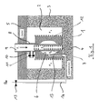
- Figure 1 shows a forming tool 1, which is set up in a pressure chamber 2, which is delimited by walls 3, a bottom 4 and a "cover 5".
- the forming tool 1 has in its interior a recess 6, the contour of which corresponds to that of a workpiece to be produced.
- the workpiece is produced from a workpiece blank 7, which here is a tube inserted into the recess 6.
- the forming tool 1 or the interior of the workpiece blank 7 are via a pressure medium line 8 through the cover 5 from the Pressure chamber 2 is led out with a pressure medium connection 9 in connection.
- a branch line 10 branches off from the pressure medium line 8, in which a first pressure control valve 11 is arranged.
- the interior of the workpiece blank 7 can thus be subjected to the forming pressure p i via the pressure medium connection 9.
- pressure control valve 11 By opening the pressure control valve 11, pressure medium can reach the pressure chamber 2 from the pressure medium connection 9.
- the "back pressure” or “compensation pressure” p a prevailing in the pressure chamber 2 presses against the forming tool 1 from the outside, which is represented by arrows 12.
- a spur line 13 leads down to the bottom 4 of the pressure chamber 2.
- the vent line 14 is connected to ambient pressure p ⁇ via a second control valve 15.
- a forming pressure p i is applied to the inside of the workpiece via the pressure medium connection 9.
- the workpiece blank 7 gradually deforms in accordance with the inner contour of the recess 6.
- the air trapped between the workpiece blank 7 and the recess 6 can escape via the ventilation line 14 when the control valve 15 is open.
- the pressure p 0 in the recess 6 can thus be regulated by the control valve 15.
- the pressure chamber 2 can be pressurized via the spur line 10 and the first control valve 11.
- the compensation pressure p a prevailing in the pressure chamber 2 presses against the tool from the outside, as a result of which the internal pressure prevailing in the tool is at least partially compensated.
- the compensation pressure p a p ie the forming pressure by the mechanical stress generated i of the forming tool 1 is reduced.
- the forming tool 1 can less here massive and therefore more cost-effective.
- Another A significant advantage of the invention is that the pressure chamber 2 is tool-independent. That is, different can in the pressure room 1 Tools set up and to the vent line 14 and the Pressure medium connection 9 are connected.
- FIG. 2 shows an embodiment in which, in contrast to FIG. 1, the pressure medium connection 9 or the pressure medium line 8 is additionally connected to the ventilation line 14 via a connecting line 16 and a pressure control valve 17.
- the "system” can also be subjected to constant pressure first and the pressure for forming can be released. This results in an additional possibility to regulate the "system".
Landscapes
- Physics & Mathematics (AREA)
- Fluid Mechanics (AREA)
- Engineering & Computer Science (AREA)
- Mechanical Engineering (AREA)
- Shaping Metal By Deep-Drawing, Or The Like (AREA)
- Moulds For Moulding Plastics Or The Like (AREA)
Abstract
Description
- Fig. 1
- ein erstes Ausführungsbeispiel gemäß der Erfindung; und
- Fig 2
- ein zweites Ausführungsbeispiel gemäß der Erfindung.
Claims (14)
- Umformvorrichtung mit einem Umformwerkzeug, in das ein zu verformendes Werkstück einbringbar ist, wobei das Umformwerkzeug einen Druckmittelanschluss zum Aufbringen eines Umformdrucks auf das Werkstück aufweist, dadurch gekennzeichnet, dass
das Umformwerkzeug (1) in einem Druckraum (2) angeordnet ist, und dass eine Einrichtung (9-11) zum Erzeugen eines in dem Druckraum (2) herrschenden, von außen auf das Umfomwerkzeug (1) wirkenden Stabilisierungsdrucks (pa ) vorgesehen ist. - Umformvorrichtung nach Anspruch 1, dadurch gekennzeichnet, dass der Druckraum (2) einen Druckeingang (10) aufweist, welcher mit dem Druckmittelanschluss (9) des Umformwerkzeugs (1) in Druckverbindung bringbar ist, zum zumindest teilweisen kompensieren des auf das Umformwerkzeug (1) wirkenden Innendrucks.
- Umformvorrichtung nach Anspruch 2, dadurch gekennzeichnet, dass der Druckeingang (10) mit dem Druckmittelanschluss (9) über eine erste Druckregeleinrichtung (11) verbunden ist, zum Regeln des im Druckraum (2) herrschenden auf das Umformwerkzeug (1) wirkenden Stabilisierungsdrucks (pa).
- Umformvorrichtung nach einem der Ansprüche 1 bis 3, dadurch gekennzeichnet, dass das Umformwerkzeug (1) eine Ausnehmung (6) aufweist, deren Form der herzustellenden Außenform des Werkstücks (7) entspricht und dass das Umformwerkzeug (1) einen Druckentlastungsanschluss (13) aufweist, über den Entlüftungsdruck (p0) aus der Ausnehmung (6) abgelassen werden kann.
- Umformvorrichtung nach Anspruch 4, dadurch gekennzeichnet, dass der Druckentlastungsanschluss (13) über eine Entlüftungsleitung (14) und einen zweiten Druckregler (15) zur Atmosphäre (p∞) hin entlüftbar ist, wobei der zweite Druckregler (15) zur Regelung des während des Umformvorganges zwischen dem Werkstück (7) und dem Umformwerkzeug (1) herrschenden Drucks (p0) vorgesehen ist.
- Umformvorrichtung nach einem der Ansprüche 1 bis 5, dadurch gekennzeichnet, dass eine Regeleinrichtung (11, 15) vorgesehen ist, zur Regelung des Umformdrucks (pi), des Stabilisierungsdrucks (pa) und des Entlüftungsdrucks (p0), in Abhängigkeit vom Verformungszustand des Werkstücks (7).
- Umformvorrichtung nach einem der Ansprüche 1 bis 6, dadurch gekennzeichnet, dass der Stabilisierungsdruck (pa) und der Entlüftungsdruck (p0) so geregelt werden, dass die mechanische Belastung des Umformwerkzeugs (1) minimal ist.
- Umformvorrichtung nach einem der Ansprüche 1 bis 7, dadurch gekennzeichnet, dass der Druckmittelanschluss (9) außerhalb des Druckraums (2) angeordnet ist und über eine Druckmittelleitung (8) mit einem im zu verformenden Werkstück (7) vorgesehenen Hohlraum verbunden ist.
- Umformvorrichtung nach einem der Ansprüche 1 bis 8, dadurch gekennzeichnet, dass der Druckraum (2) eine Öffnungs/Verschließeinrichtung (5) aufweist, zum Einbringen bzw. Herausnehmen des Umformwerkzeugs (1).
- Umformvorrichtung nach einem der Ansprüche 8 oder 9, dadurch gekennzeichnet, dass die Druckmittelleitung (8) durch die Öffnungs/Verschließeinrichtung (5) aus dem Druckraum (2) herausgeführt ist.
- Umformvorrichtung nach einem der Ansprüche 1 bis 10, dadurch gekennzeichnet, dass der Druckraum (2) im Erdreich versenkt ist.
- Umformvorrichtung nach einem der Ansprüche 1 bis 11, dadurch gekennzeichnet, dass das Umformwerkzeug (1) eine gerundete Außenform hat.
- Umformvorrichtung nach einem der Ansprüche 1 bis 12, dadurch gekennzeichnet, dass das Umformwerkzeug (1) eine kugelförmige Außengeometrie hat.
- Umformvorrichtung nach einem der Ansprüche 5 bis 13, dadurch gekennzeichnet, dass der Druckmittelanschluß (9) über eine Verbindungsleitung (16) und ein Druckregelventil (17) mit der Entlüftungsleitung (14) verbunden ist.
Applications Claiming Priority (2)
| Application Number | Priority Date | Filing Date | Title |
|---|---|---|---|
| DE2001139135 DE10139135A1 (de) | 2001-08-09 | 2001-08-09 | Umformvorrichtung, insbesondere zur Innenhochdruckumformung |
| DE10139135 | 2001-08-09 |
Publications (2)
| Publication Number | Publication Date |
|---|---|
| EP1283081A2 true EP1283081A2 (de) | 2003-02-12 |
| EP1283081A3 EP1283081A3 (de) | 2003-11-05 |
Family
ID=7694906
Family Applications (1)
| Application Number | Title | Priority Date | Filing Date |
|---|---|---|---|
| EP02015272A Withdrawn EP1283081A3 (de) | 2001-08-09 | 2002-07-09 | Umformung, insbesondere zur Innenhochdruckformung |
Country Status (2)
| Country | Link |
|---|---|
| EP (1) | EP1283081A3 (de) |
| DE (1) | DE10139135A1 (de) |
Cited By (1)
| Publication number | Priority date | Publication date | Assignee | Title |
|---|---|---|---|---|
| CN102049442A (zh) * | 2010-10-28 | 2011-05-11 | 北京航空航天大学 | 一种发动机中用密封环成型方法及模具装置 |
Families Citing this family (2)
| Publication number | Priority date | Publication date | Assignee | Title |
|---|---|---|---|---|
| DE10356534B3 (de) * | 2003-12-04 | 2004-09-09 | Daimlerchrysler Ag | Umformwerkzeug |
| DE102009056405A1 (de) | 2009-12-01 | 2011-06-09 | Daimler Ag | Umformeinrichtung |
Family Cites Families (7)
| Publication number | Priority date | Publication date | Assignee | Title |
|---|---|---|---|---|
| JPS6096333A (ja) * | 1983-10-28 | 1985-05-29 | Hitachi Ltd | 円筒容器の保持方法 |
| US5419171A (en) * | 1993-10-14 | 1995-05-30 | The Boeing Company | Isostatic bulge forming |
| DE19513444C2 (de) * | 1995-04-13 | 1999-12-23 | Konrad Schnupp | Vorrichtung zum hydromechanischen Umformen |
| DE19516064C2 (de) * | 1995-05-04 | 1998-01-29 | Rasselstein Ag | Verfahren zur Herstellung eines Blechbehälters mit im wesentlichen bauchiger Form |
| GB9621831D0 (en) * | 1996-10-19 | 1996-12-11 | Metal Box Plc | Reshaping of containers |
| DE19705244A1 (de) * | 1997-02-12 | 1998-08-13 | Huber & Bauer Gmbh | Umformvorrichtung |
| DE19712128A1 (de) * | 1997-03-22 | 1998-09-24 | Wdb Ringwalztechnik Gmbh | Verfahren zum Zusammenhalt zweier geteilter Werkzeuge oder Gesenke, die mit Innendruck beaufschlagt werden und Vorrichtung zur Durchführung des Verfahrens |
-
2001
- 2001-08-09 DE DE2001139135 patent/DE10139135A1/de not_active Withdrawn
-
2002
- 2002-07-09 EP EP02015272A patent/EP1283081A3/de not_active Withdrawn
Cited By (2)
| Publication number | Priority date | Publication date | Assignee | Title |
|---|---|---|---|---|
| CN102049442A (zh) * | 2010-10-28 | 2011-05-11 | 北京航空航天大学 | 一种发动机中用密封环成型方法及模具装置 |
| CN102049442B (zh) * | 2010-10-28 | 2014-10-29 | 北京航空航天大学 | 一种发动机中用密封环成型方法及模具装置 |
Also Published As
| Publication number | Publication date |
|---|---|
| EP1283081A3 (de) | 2003-11-05 |
| DE10139135A1 (de) | 2003-02-20 |
Similar Documents
| Publication | Publication Date | Title |
|---|---|---|
| EP0523215B1 (de) | Verfahren zum hydrostatischen umformen von hohlkörpern aus kaltumformbarem metall und vorrichtung zur durchführung des verfahrens | |
| EP2694230B1 (de) | Radialpresse | |
| EP3415247A1 (de) | Verfahren und vorrichtung zum umformen | |
| EP0879657A2 (de) | Verfahren und Vorrichtung zum Herstellen eines Hohlkörpers | |
| DE19924310B4 (de) | Hydraulische Antriebseinrichtung für ein Fügewerkzeug | |
| DE19717953A1 (de) | Verfahren zum hydromechanischen Stülpziehen von Metallblechen | |
| DE10248329A1 (de) | Verfahren und Vorrichtung zum wirkmedienbasierten Umformen eines Bauteilrohling | |
| DE10237233B4 (de) | Spanneinrichtung einer Feinbearbeitungsvorrichtung und Verfahren zum verformungsangepassten Feinbearbeiten eines Werkstücks unter Einsatz der Spanneinrichtung | |
| DE102016204209B4 (de) | Einsetzvorrichtung und Verfahren zum Einsetzen eines Rondenrings in einen Außenring einer Ronde | |
| EP1283081A2 (de) | Umformung, insbesondere zur Innenhochdruckformung | |
| DE4218497A1 (de) | Vorrichtung und verfahren zum woelben von behaelterboeden | |
| DE3938944A1 (de) | Druckregler fuer den kraftstoff-kreislauf des zufuhrsystemes eines verbrennungsmotors | |
| DE10027079A1 (de) | Verfahren und Vorrichtung zum Umformen eines plattenförmigen Werkstücks | |
| DE10048005B4 (de) | Vorrichtung zum Verbinden mindestens zweier flächiger, übereinander liegender Bauteile | |
| DE102014101616B4 (de) | Hydraulisches Ziehkissen einer Ziehpresse und Verfahren zum Betreiben des hydraulischen Ziehkissens | |
| DE19751408C2 (de) | Verfahren und Vorrichtung zur Herstellung eines Integralgehäuses für Hydrolenkung | |
| DE102022100748B3 (de) | Selbstsichernde, fluidische Klemmvorrichtung | |
| DE3114485A1 (de) | "verfahren und vorrichtung zum kalibrieren rohrfoermiger gegenstaende" | |
| DE102005036419B4 (de) | Vorrichtung zur Herstellung ausgebauchter Hohlprofile, insbesondere von Gasgeneratorgehäusen für Airbageinrichtungen | |
| DE102006052696B4 (de) | Verfahren und Vorrichtung zum Umformen von Halbzeugen | |
| DE10344941B4 (de) | Vorrichtung zum Steuern einer Werkstückhaltekraft einer Presse zum Tiefziehen von Werkstücken | |
| DE102024208384B3 (de) | Verfahren zum Aufweiten und Anlegen eines Rollbalgs an ein Anschlussteil einer Luftfeder und Vorrichtung zum Durchführen solch eines Verfahrens | |
| DE10016804B4 (de) | Verfahren und Vorrichtung zum Herstellen von Bauteilen aus einer tiefziehbaren Platine | |
| DE102005055452B4 (de) | Verfahren und Vorrichtung zum Hochdruckumformen | |
| DE10030792C2 (de) | Mehrstufenpresse, insbesondere Quertransportpresse, mit hydraulischer Schließvorrichtung |
Legal Events
| Date | Code | Title | Description |
|---|---|---|---|
| PUAI | Public reference made under article 153(3) epc to a published international application that has entered the european phase |
Free format text: ORIGINAL CODE: 0009012 |
|
| AK | Designated contracting states |
Designated state(s): AT BE BG CH CY CZ DE DK EE ES FI FR GB GR IE IT LI LU MC NL PT SE SK TR |
|
| AX | Request for extension of the european patent |
Extension state: AL LT LV MK RO SI |
|
| PUAL | Search report despatched |
Free format text: ORIGINAL CODE: 0009013 |
|
| AK | Designated contracting states |
Kind code of ref document: A3 Designated state(s): AT BE BG CH CY CZ DE DK EE ES FI FR GB GR IE IT LI LU MC NL PT SE SK TR |
|
| AX | Request for extension of the european patent |
Extension state: AL LT LV MK RO SI |
|
| AKX | Designation fees paid | ||
| REG | Reference to a national code |
Ref country code: DE Ref legal event code: 8566 |
|
| STAA | Information on the status of an ep patent application or granted ep patent |
Free format text: STATUS: THE APPLICATION IS DEEMED TO BE WITHDRAWN |
|
| 18D | Application deemed to be withdrawn |
Effective date: 20040506 |