EP1282885B1 - Systeme de comptage d'etres vivants - Google Patents
Systeme de comptage d'etres vivants Download PDFInfo
- Publication number
- EP1282885B1 EP1282885B1 EP01921484A EP01921484A EP1282885B1 EP 1282885 B1 EP1282885 B1 EP 1282885B1 EP 01921484 A EP01921484 A EP 01921484A EP 01921484 A EP01921484 A EP 01921484A EP 1282885 B1 EP1282885 B1 EP 1282885B1
- Authority
- EP
- European Patent Office
- Prior art keywords
- task
- cells
- living beings
- cell
- counting
- Prior art date
- Legal status (The legal status is an assumption and is not a legal conclusion. Google has not performed a legal analysis and makes no representation as to the accuracy of the status listed.)
- Expired - Lifetime
Links
Images






Classifications
-
- G—PHYSICS
- G06—COMPUTING OR CALCULATING; COUNTING
- G06M—COUNTING MECHANISMS; COUNTING OF OBJECTS NOT OTHERWISE PROVIDED FOR
- G06M1/00—Design features of general application
- G06M1/08—Design features of general application for actuating the drive
- G06M1/10—Design features of general application for actuating the drive by electric or magnetic means
- G06M1/101—Design features of general application for actuating the drive by electric or magnetic means by electro-optical means
-
- G—PHYSICS
- G07—CHECKING-DEVICES
- G07C—TIME OR ATTENDANCE REGISTERS; REGISTERING OR INDICATING THE WORKING OF MACHINES; GENERATING RANDOM NUMBERS; VOTING OR LOTTERY APPARATUS; ARRANGEMENTS, SYSTEMS OR APPARATUS FOR CHECKING NOT PROVIDED FOR ELSEWHERE
- G07C9/00—Individual registration on entry or exit
-
- G—PHYSICS
- G08—SIGNALLING
- G08B—SIGNALLING SYSTEMS, e.g. PERSONAL CALLING SYSTEMS; ORDER TELEGRAPHS; ALARM SYSTEMS
- G08B13/00—Burglar, theft or intruder alarms
- G08B13/16—Actuation by interference with mechanical vibrations in air or other fluid
- G08B13/1609—Actuation by interference with mechanical vibrations in air or other fluid using active vibration detection systems
- G08B13/1645—Actuation by interference with mechanical vibrations in air or other fluid using active vibration detection systems using ultrasonic detection means and other detection means, e.g. microwave or infrared radiation
-
- G—PHYSICS
- G08—SIGNALLING
- G08B—SIGNALLING SYSTEMS, e.g. PERSONAL CALLING SYSTEMS; ORDER TELEGRAPHS; ALARM SYSTEMS
- G08B13/00—Burglar, theft or intruder alarms
- G08B13/18—Actuation by interference with heat, light, or radiation of shorter wavelength; Actuation by intruding sources of heat, light, or radiation of shorter wavelength
- G08B13/189—Actuation by interference with heat, light, or radiation of shorter wavelength; Actuation by intruding sources of heat, light, or radiation of shorter wavelength using passive radiation detection systems
- G08B13/19—Actuation by interference with heat, light, or radiation of shorter wavelength; Actuation by intruding sources of heat, light, or radiation of shorter wavelength using passive radiation detection systems using infrared-radiation detection systems
- G08B13/191—Actuation by interference with heat, light, or radiation of shorter wavelength; Actuation by intruding sources of heat, light, or radiation of shorter wavelength using passive radiation detection systems using infrared-radiation detection systems using pyroelectric sensor means
Definitions
- the object of the invention is a counting system of living beings, moving on a first surface and passing through a second cylindrical surface of a generator substantially vertical.
- a system consists of a set of N cells of detection of thermal radiation and an electronic device for acquiring and treatment of the signals delivered by these cells.
- the international application WO 9210812 describes such a counting system, using a single cell that has a sensor and a lens positioned in front of it.
- This sensor is composed of two rows of pyroelectric detectors.
- the lens focuses the thermal radiation on each of the detectors.
- This type of radiation detector temperature can only detect relatively rapid changes in temperature in the field of vision.
- the cell creates two parallel surveillance plans formed by the axes of the beams associated with the detectors.
- a treatment unit evaluates the number of living crossing both planes and their directions of movement.
- This device is adapted to counting in low and low width passages, bus door example. This device is practically unusable in wide passages important given the divergence of the field of view of the sensor.
- the use of pyroelectric detectors as part of this application International makes it difficult to detect living things in slow motion.
- US Patent 4,799,243 describes another system of counting living beings in movement.
- This system consists of cells, each cell comprising two thermal radiation detectors and a lens. These two detectors create for each cell two disjoint fields of vision, substantially symmetrical with respect to the vertical.
- the arrangement of the cells as provided for in this patent is chosen for cover the entire width of the passage to be monitored with a covering of the fields vision in a direction perpendicular to the direction of crossing and a separation of fields of vision according to the direction of crossing. Such an arrangement does not allow the counting living beings too close to each other according to the direction of crossing.
- US Pat. No. 5,068,537 describes another system for counting living creatures in movement using a large number of cells arranged on a single line.
- the system is designed so that a medium-sized living being is detected by at least two cells. Since each cell has only one detector, the system does not allow the determination of the direction of crossing counted living beings.
- thermopiles that are characterized by their ability to detect even very slow variations of temperature in their field of vision.
- the counting system for living beings that is the subject of the invention comprises a set of N thermal radiation detection cells and an electronic device acquisition and processing of the signals delivered by these cells.
- Each cell comprises in particular a thermopile comprising at least one sensitive element, a medium focusing the thermal radiation on the sensitive elements of this thermopile, this focusing means creating an elongated field of view according to a direction, a mask limiting this field of view and an amplifier of the signal delivered by the thermopile.
- the N detection cells are equidistributed according to two curves when N is even and are divided along two curves with a difference of one unit when N is odd, the distribution of the cells on each curve being uniform according to an identical pitch P for each of the two curves, one of these curves identifying with the director of the surface cylindrical crossed by living beings, and the other curve being distant from the preceding of a length D equal to at least 5 cm, the direction of elongation of the field each cell being substantially tangent to one of the two curves.
- a filter generally placed in the thermopile in front of the sensitive element limits the sensitivity to thermal radiation of bodies near temperature ambient, which corresponds to far-infrared radiation in the wavelengths of about 7 to 14 ⁇ m.
- the means of focusing of each cell is adapted to the number, arrangement and geometry of the sensitive element (s) of the thermopile so as to create an elongated field of view in one direction and as narrow as possible in the direction perpendicular to the previous one.
- the means of focusing is preferably carried out using one or more lenses. he can possibly be made by pinhole or mirror.
- thermopile comprises a single sensitive element of elongated surface or when the thermopile has an alignment of sensitive elements whose surfaces have dimensions substantially similar in two directions orthogonal.
- several lenses are used, preferably when the thermopile has only one sensitive element whose surface has dimensions substantially adjacent in two orthogonal directions.
- the system which is the subject of the invention is used to count beings living through a plane; in this case, the curves on which the cells are distributed are parallel lines.
- the opening of the field of view can be chosen for each cell belonging to the same line, so as to ensure the juxtaposition of the zones seen by two successive cells on the same line, to a height close to the minimum size of a living being statistically representative of beings belonging to the population to count.
- the counting system for living beings which is the subject of the invention comprises a device electronic signal processing system delivered by the cells that operates a algorithm.
- a first task of this algorithm initializes the parameters specifying the system configuration.
- a second task of this algorithm ensures successively for each cell the reading and the processing of the numerical values delivered by the electronic device of acquisition.
- a third task of this algorithm ensures the adaptation of the sensitivity threshold of the cells.
- a fifth task of this algorithm analyzes the results of the fourth task and deduces the counting of living beings, their sense of crossing and their movement speed.
- a sixth task of this algorithm exploits counting as well obtained according to the intended application.
- a seventh task of this algorithm manages the rate of execution of the preceding tasks according to the sampling frequency of the signals delivered by the cells.
- the fifth task of the algorithm can be conceived in such a way that allow the grouping, as entities, of successive cell pairs for which the information from the fourth task of the algorithm corresponds crossing a living being or a group of living creatures, information from couples of each entity specifying this number of living beings, the meaning of their crossing and the speed of their movement.
- the counting system of living beings which is the subject of the invention offers various advantages by compared to known systems and in particular its easy integration for any width of passage to watch; its excellent counting performance even for a low passage height; its adaptability of implantation in environments individuals; its ability to count dense crowds and moving living things slow.
- the counting system of living beings which is the subject of the invention can be described as a non with the following example illustrated in FIGS. 1 to 14. This example corresponds to counting human beings crossing a plane, using eight cells equidistributed on two straight lines.
- FIG. 1 schematically represents a system that is the subject of the invention comprising eight cells arranged in two alignments.
- Figures 2a and 2b show two views of a radiation detection cell thermal system used in the system shown schematically in Figure 1.
- Figure 3 shows a network of Fresnel lenses used in the cell shown at Figures 2a and 2b.
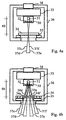
- Figures 4a and 4b show the cell shown in Figures 2a and 2b with its field of vision.
- FIGS. 5a and 5b show two views, in two orthogonal directions, of a group of two successive cells, each belonging to an alignment different, as well as the fields of view of these cells.
- FIG. 6a represents, in plan view, five successive cells belonging to the system shown in Figure 1.
- FIGS. 6b and 6c represent, in plan view, the zones seen by the five cells schematically in Figure 6a, respectively at 1 m and at ground level.
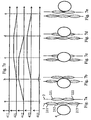
- FIGS. 7a to 7e show, in plan view, five successive phases of the crossing of a human being perpendicular to the cell alignments and for a representation of the zones seen according to FIG. 6b.
- FIG. 7z schematizes the temporal evolution of the signals delivered by the thermopile of each cell, for the crossing defined by FIGS. 7a to 7e.
- FIGS. 8a to 8e show, in plan view, five successive phases of the crossing a human being obliquely to the cell alignments and for a representation of the zones seen according to FIG. 6b.
- FIG. 8z schematizes the temporal evolution of the signals delivered by the thermopile of each cell, for the crossing defined by Figures 8a to 8e.
- Figure 9 shows the chronological sequence, in the form of a flowchart, of different tasks of processing electrical signals, delivered by the cells.
- FIGS 10, 11, 12 and 13 show four particular tasks in the flowchart shown in Figure 9.
- Figure 14 shows the table used by the particular task shown in Figure 13.
- Figure 1 shows the ground 0, a set of eight radiation detection cells distributed in two alignments, a first alignment 1 comprising four cells 11; 12; 13; 14, a second alignment 2 comprising four cells 21; 22; 23; 24, two human beings 4 and 5, an electronic device 6 for acquiring and digitization of the signals delivered by the cells, these signals possibly being at the cell level, an electronic device 7 for processing digital values delivered by the acquisition device 6, an operating device 8 information from the processing device 7, a medium 3 connecting all the cells to the acquisition device 6.
- the eight cones 111 to 114 and 121 to 124 schematize the fields of view of each of the cells. The intersections of these cones with a plane parallel to the ground 0 and located at a height of 1 m define the areas seen at this height and are schematized by the eight ellipses 211 to 214 and 221 to 224.
- Figure 2a is a schematic section of a cell in a plane perpendicular to two cell alignments.
- Figure 2b is a schematic section of the same cell, orthogonal to the section shown in Figure 2a.
- This cell comprises a thermopile 30 whose sensitive element 31 provides a signal small amplitude proportional to the thermal radiation received through of the infrared filter 32, a signal amplification and shaping stage 33 delivered by the thermopile 30, a device 38 connecting the amplification stage and shaping 33 to medium 3, a network of Fresnel lenses 34 away focal length 40, placed at a distance equal to this focal length 40 in front of the sensitive element 31 of the thermopile 30, a mask 35 placed in front of the Fresnel lens array 34 and a waterproof housing 36, opaque to electromagnetic radiation and whose surface Inner absorbs thermal radiation.
- the Fresnel Lens Network 34 has eight elements 34a to 34h.
- FIG 3 shows the Fresnel lens array 34.
- This network is composed of eight elemental Fresnel lenses 34a to 34h. These lenses are juxtaposed and their centers optics are aligned along the line 39.
- FIGS. 4a and 4b show the cell shown in FIGS. 2a and 2b according to the same projections. These figures show the elementary fields of vision 37c, 37d, 37e and 37f associated with unmasked elemental Fresnel lenses 34c, 34d, 34e and 34f.
- FIGS. 5a and 5b show successive cells 11 and 21 as well as their fields 111 and 121 respectively. These two cells belong to a different alignment.
- Figure 5a shows the fields of view perpendicular to the direction of travel normal human beings.
- Figure 5b shows the fields of view in the sense of normal movement of human beings.
- the view represented in FIG. 5a highlights the weak opening of the fields of vision 111 and 121 as well as the short distance D 42 between the two alignments 1 and 2.
- the view represented in FIG. 5b highlights the important opening of the fields of 111 and 121 as well as the half P / 2 step 41 between these cells.
- Figure 6a shows a top view of the five cells 11; 21; 12; 22; 13 disposed along the two alignments 1 and 2 distant from the distance D 42. This view also shows the half-pitch P / 2 41 between two successive cells.
- Figure 6b shows in plan view the arrangement of the zones 211; 221; 212; 222; 213 viewed at a height of 1 m above ground level 0 and corresponding respectively cells 11; 21; 12; 22; 13. This figure 6b highlights the juxtaposition of zones seen by two successive cells arranged on the same alignment.
- FIG. 6c shows in plan view the arrangement of the zones seen at ground level 0, 311; 321; 312; 322; 313 respectively corresponding to the cells 11; 21; 12; 22; 13. This figure 6c highlights the partial superposition of the zones seen by two successive cells arranged on the same alignment.
- FIGS. 7a to 7e respectively represent, in plan view, five phases successive a, b, c, d, e crossing a human being 4 perpendicular to the alignments 1 and 2, as well as the areas seen at a height of 1 m above the level of the ground, shown in Figure 6b.
- Figure 7z shows the waveforms of the signals electric 411; 421; 412; 422; 413 delivered respectively by the cells 11; 21; 12; 22; 13.
- the level of each electrical signal 411; 421; 412; 422; 413 is related to the fraction of the view area occupied by the human being that crosses the fields of view of cells 11; 21; 12; 22; 13.
- phase a the human being 4 is not present in any of the zones 211; 221; 212; 222; 213. Electrical signals 411; 421; 412; 422; 413 shown in the figure 7z have a zero level.
- phase b the human being 4 completely occupies the view area 212.
- the signal level 412 is maximal.
- the human being 4 occupies very partially the zone seen 213.
- the level signal 413 has a peak of very low amplitude.
- the zones viewed 211; 221; 222 does not are not occupied by the human being 4.
- the levels of the corresponding signals 411; 421; 422 remain void.
- phase c the human being 4 continues to occupy the entire area 212.
- signal level 412 remains maximum.
- Human being 4 partially occupies the views 221 and 222.
- the level of the signals 421 and 422 is average.
- the zones seen 211 and 213 do not are not occupied by the human being 4.
- the corresponding signal levels 411 and 413 remain void.
- phase d the human being 4 leaves the view area 212.
- the signal level 412 becomes zero again.
- the human being 4 continues to occupy partially the zones seen 221 and 222.
- the level of the signals 421 and 422 remains average.
- the zones seen 211 and 213 are not not occupied by humans 4.
- Corresponding signal levels 411 and 413 remain void.
- phase e the human being 4 leaves the zones seen 221 and 222.
- the level of the signals 421 and 422 become void again.
- the zones viewed 211; 212; 213 are not occupied by being human 4.
- Levels of corresponding signals 411; 412; 413 remain void.
- FIGS. 8a to 8e respectively represent, in plan view, five phases successive a, b, c, d, e of the crossing of a human being obliquely to the alignments 1 and 2, as well as the areas seen at a height of 1 m above ground level, shown in Figure 6b.
- FIG. 8z schematizes the oscillograms of the electrical signals 511; 521; 512; 522; 513 issued respectively by the cells 11; 21; 12; 22; 13.
- the level of each electrical signal 511; 521; 512; 522; 513 is related to the fraction of the view area occupied by the human being which passes through the fields of view of the cells 11; 21; 12; 22; 13.
- phase a the human being is not present in any of the zones seen 211; 221; 212; 222; 213. Electrical signals 511; 521; 512; 522; 513 shown in the figure 8z have a zero level.
- phase b the human being 5 partially occupies the zones 212 and 213.
- signal level 512 and 513 is average.
- the zones viewed 211; 221; 222 are not occupied by the human being 5.
- Levels of the corresponding signals 511; 521; 522 are zero.
- phase c the human being occupies almost entirely the area viewed 212.
- the level signal 512 reaches a maximum.
- the human being 5 partially occupies the views 221 and 222.
- the level of the signals 521 and 522 is average.
- the zones seen 211 and 213 do not are not occupied by the human being 5.
- the levels of the corresponding signals 511 and 513 remain void.
- phase d the human being 5 leaves the zones seen 212 and 222.
- the level of the signals 512 and 522 becomes zero again.
- the human being occupies the entire zone 221.
- signal 521 reaches a maximum.
- the views 211 and 213 are not occupied by 5.
- the levels of the corresponding signals 511 and 513 remain zero.
- phase e the human being leaves the view zone 221.
- the level of the signal 521 becomes again no.
- the zones viewed 211; 212; 213; 222 are not occupied by humans. corresponding signal levels 511; 512; 513; 522 remain void.
- Figure 9 shows the chronological sequence, in the form of a flowchart, of different tasks of real-time processing of numerical values from the device electronic 6 acquisition and digitization of electrical signals 411; 421; 412; 422; 413, delivered by the five cells 11; 21; 12; 22; 13.
- This chart is put implemented by the electronic device 7.
- the flow chart of Figure 9 has a point 601 and an exit point 699. It has seven tasks 603; 700; 800; 900; 1000; 605; 607.
- Task 603 allows the initialization of parameters specifying the configuration of the system Count: number of cells, height of cells relative to the ground, not P and distance D as well as processing parameters: sampling frequency of electrical signals delivered by the cells and initial sensitivity threshold of the cells.
- the task 603 sets the cells to the INVALID stored state as well as the pairs of successive cells, that is to say the pairs such as the pair 11; 21 followed by a couple 21; 12, himself followed by the pair 12; 22 and so on, in the stored state INVALID.
- Task 700 provides successively for each cell the reading and processing of digital values delivered by the electronic device 6.
- the task 800 ensures for the system object of the invention the adaptation of the threshold of cell sensitivity used by task 700.
- the task 900 analyzes for all the successive pairs of cells, the information from task 700.
- the task 1000 analyzes the results of the task 900 and deduces the count of the beings humans.
- the task 605 allows the operation by the electronic device 8, of the metering carried out by the task 1000, depending on the intended application.
- Task 607 manages the execution rate of tasks 700 to 605 according to the frequency sampling; this task 607 is executed at each instant (t). To this end, the task 607 delays connection 607/1 to task 700. Task 607 also allows to definitively leave the execution of the tasks 700 to 605 by the connection 607/0 towards the exit point 699.
- an index k is associated with each cell.
- the value 1 of the index k is associated with an extreme cell, 11 for example; the value 2 of the index k is associated with the successive cell, here the cell 21, and so on.
- an index m is associated with each pair of successive cells.
- the value 1 of the index m is associated with an extreme pair, 11; 21 for example; the value 2 of the index m is associated with the successive pair, here the pair 21; 12, and so on.
- Figures 10, 11, 12 and 13 show respectively in the form of flowcharts the chronological sequence of the elementary tasks constituting the tasks 700; 800; 900 and 1000.
- entry point 701 and exit point 799 of task 700 are shown. This task repeats for each digital value delivered by the electronic device 6 elementary tasks 705 to 719.
- the task 703 initializes to 1 the index k associated with the cell which is read and whose numerical value.
- Task 705 controls the acquisition and digitization by the electronic device 6 the electrical signal delivered at the instant (t) by the cell in question.
- Task 707 handles the processing of the numerical value delivered by task 705 in order to homogenization of all the digital values of the delivered signals.
- the task 709 stores the value processed by the task 707 if it corresponds to a local maximum, determined from values previously processed by task 707 for this cell.
- the value stored by task 709 is used for adaptation in the task 800 of the sensitivity threshold of the cells.
- the test 711 verifies the superiority of the value processed by the task 707 on the threshold of sensitivity of the cells.
- Connection 711/1 is effective if test 711 is TRUE; in this case a human being is in the field of view of the cell in question.
- the task 712 stores the value processed by the task 707 and the instant (t); she positions the cell considered in the instantaneous ACTIVE state.
- the 711/0 connection is effective if the test 711 is FALSE.
- the test 713 verifies the superiority of the value processed by the task 707 on the threshold of cell sensitivity, at the previous instant (t-1).
- Branch 713/1 is effective if test 713 is TRUE; in this case a human being just left the field of view of the cell in question; task 715 analyzes the successive values stored by the task 712 to extract information Characteristics of the crossing of a human being: moment of beginning of the crossing, instant end of the crossing, instant corresponding to the median of the stored values and average of these values; it positions the cell in the stored state VALID. All this information is stored for analysis by task 900.
- test 713 is FALSE; in this case, no being human being is in the field of view of the cell considered.
- the task 714 positions the cell in the instantaneous PASSIVE state.
- Task 717 increments the index k associated with a cell.
- the test 719 verifies that the new index k is less than or equal to the total number of cells.
- Branch 719/1 is effective if test 719 is TRUE; in this case all the cells have not been processed and go back to task 705.
- the 719/0 connection is effective if the test 719 is FALSE; in this case all the cells have been treated.
- entry point 801 and exit point 899 of task 800 are shown.
- This task has two elementary tasks 803 and 805 ensuring the adaptation of the threshold of sensitivity of the cells according to the last V values memorized by the task 709 of Figure 10; V being chosen arbitrarily according to the application, by example depending on the frequency of crossing of living beings or according to a fixed number of crossings; this number can be chosen in the range from 20 to 100.
- the 803 test checks that all the cells are in the PASSIVE instant state and that minus V values have been stored by task 709 of task 700.
- the 803/1 connection is effective if the 803 test is TRUE; in this case, the threshold of Cell sensitivity can be adapted.
- Task 805 calculates the rolling average over all last V values memorized by the task 709 of FIG. 10 and deduces therefrom the new sensitivity threshold cells.
- the 803/0 connection is effective if the 803 test is FALSE; in this case the threshold of Cell sensitivity can not be adapted.
- entry point 901 and exit point 999 of task 900 are shown. This task repeats elementary tasks 905 to 911 for each pair of cells. analyzes the extracted characteristic information for each cell by task 700 and deduces the characteristic information of each couple.
- the task 903 initializes to 1 the index m associated with the pair of cells to be analyzed.
- the test 905 verifies that the two cells forming the couple considered are in the state memorized VALID and that there is a period of common occupation during which the human being is simultaneously in the field of vision of the two cells, which amounts to to consider that the human being is in the field of vision of the couple.
- the 905/1 connection is effective if the 905 test is TRUE.
- Task 907 analyzes the extracted characteristic information for each cell of the couple of successive cells considered and deduces the characteristic information of the crossing of a human being for this couple: moment of beginning of common occupation, moment of end of common occupation, average of the couple, that is to say average of the averages calculated for the couple's cells, signature of the occupation chronology couple cells; the state of the pair of successive cells is considered as VALID.
- the signature of the chronology of occupation of the cells of the couple is chosen arbitrarily POSITIVE if the human crosses the alignment 1 then the alignment 2 and NEGATIVE if the human crosses the alignment 2 then the alignment 1.
- the 905/0 connection is effective if the 905 test is FALSE.
- Task 909 increments the index m associated with a pair.
- the 911 test verifies that the new index m is less than or equal to the total number of couples.
- the 911/1 connection is effective if the 911 test is TRUE; in this case all couples have not been analyzed and we return to the 905 test.
- the 911/0 connection is effective if the 911 test is FALSE; in this case all couples have been analyzed.
- the task 1003 initializes to 1 the index m associated with the pair of cells to be analyzed and initialises to zero the contents of the entity, which means that the entity contains no couple.
- the test 1005 verifies that the couple considered is in the VALID state.
- the 1005/0 connection is effective if the 1005 test is FALSE.
- Task 1006 resets the contents of the entity to zero, which means that the entity does not contains no couple.
- the 1005/1 connection is effective if the 1005 test is TRUE.
- Task 1007 includes the couple considered in the entity.
- Test 1009 verifies that there is a period of time during which one or more beings humans are in the field of view of the couple considered and the next couple.
- the 1009/0 connection is effective if the 1009 test is FALSE; in this case, the entity is complete, it can be analyzed to count human beings.
- Task 1011 uses the table shown in Figure 14 to analyze the entity and to determine in real time the number of human beings and their direction of passage.
- Task 1013 updates the characteristic information of couples and cells contained in the entity and then re-initializes the content of the entity to 0. The state of these couples and the stored state of these cells are repositioned in the INVALID state.
- the 1009/1 connection is effective if the 1009 test is TRUE; in this case, the couple next is likely to be included in the entity.
- Task 1015 increments the index m associated with a pair.
- Test 1017 verifies that the new index m is less than or equal to the total number of couples.
- Connection 1017/1 is effective if test 1017 is TRUE; in this case all couples have not been analyzed and we return to the 1005 test.
- the 1017/0 connection is effective if the test 1017 is FALSE; in this case all couples were analyzed.
- Figure 14 shows the characteristic number analysis chart of the created entity during task 1000.
- This array has as many columns and rows as there are cells in the system.
- This table defines the number of human beings associated with the entity as well as their direction of crossing according to the characteristic numbers of the entity.
- the column numbers correspond to the possible values taken by the number X and the line numbers correspond to the possible values taken by the number Y.
- the empty boxes in the table correspond to impossible situations; the other boxes of the array include either a letter or at least one signed integer whose module represents the number of human beings counted and whose sign corresponds to the crossing initial alignment 1 if it is positive and at the initial crossing of alignment 2 if it is negative
- the letters A, B and C of the table correspond to the special cases for which the counting of human beings is conditioned by additional information.
- the letter A is to be replaced by (+1) when the average of the couple having the signature POSITIVE is greater than the average of the couple with the NEGATIVE signature.
- the letter A is to be replaced by (-1) when the average of the couple having the signature POSITIVE is less than the average of the couple with the NEGATIVE signature.
- the letter B is to be replaced by the set (+1) & (-1) when the couple having the POSITIVE signature was included in the entity before or after the other pairs and by (-2) in other cases.
- the letter C is to be replaced by the set (+1) & (-1) when the couple having the NEGATIVE signature was included in the entity before or after the other couples and by (+2) in other cases.
Landscapes
- Physics & Mathematics (AREA)
- General Physics & Mathematics (AREA)
- Theoretical Computer Science (AREA)
- Toxicology (AREA)
- General Health & Medical Sciences (AREA)
- Engineering & Computer Science (AREA)
- Health & Medical Sciences (AREA)
- Investigating Or Analysing Biological Materials (AREA)
- Measuring And Recording Apparatus For Diagnosis (AREA)
- Measuring Pulse, Heart Rate, Blood Pressure Or Blood Flow (AREA)
- Radar Systems Or Details Thereof (AREA)
- Geophysics And Detection Of Objects (AREA)
- Measurement And Recording Of Electrical Phenomena And Electrical Characteristics Of The Living Body (AREA)
- Photometry And Measurement Of Optical Pulse Characteristics (AREA)
Description
Claims (10)
- Système de comptage d'êtres vivants se déplaçant sur une première surface (0) et traversant une seconde surface cylindrique de génératrice sensiblement verticale, constitué d'un ensemble de N cellules (11) de détection de rayonnement thermique ainsi que d'un dispositif électronique d'acquisition et de traitement des signaux délivrés par ces cellules, caractérisé en ce que chacune de ces cellules comporte une thermopile (30) comprenant au moins un élément sensible (31), un moyen focalisant (34) le rayonnement thermique sur les éléments sensibles de cette thermopile, ce moyen de focalisation créant un champ de vision (111) allongé selon une direction, un masque (35) limitant ce champ de vision et un amplificateur du signal délivré par la thermopile (30) et caractérisé en ce que les N cellules (11) de détection sont équiréparties entre deux courbes lorsque N est pair et sont réparties entre deux courbes avec une différence d'une unité lorsque N est impair, la répartition des cellules sur chaque courbe étant uniforme selon un pas P identique pour chacune des deux courbes, l'une de ces courbes s'identifiant à la directrice de la surface cylindrique traversée par les êtres vivants, et l'autre courbe étant distante de la précédente d'une longueur D (42) égale à 5 cm au moins, la direction d'allongement du champ de vision de chaque cellule étant sensiblement tangente à l'une des deux courbes.
- Système de comptage d'êtres vivants conforme à la revendication 1, caractérisé en ce que le moyen de focalisation (34) de chaque cellule est réalisé à l'aide d'une seule lentille et en ce que la thermopile comporte un seul élément sensible de surface allongée ou un alignement d'éléments sensibles dont les surfaces ont des dimensions sensiblement voisines selon deux directions orthogonales.
- Système de comptage d'êtres vivants conforme à la revendication 1, caractérisé en ce que le moyen de focalisation (34) de chaque cellule est réalisé à l'aide de plusieurs lentilles et en ce que la thermopile ne comporte qu'un seul élément sensible dont la surface a des dimensions sensiblement voisines selon deux directions orthogonales.
- Système de comptage d'êtres vivants conforme à la revendication 1, caractérisé en ce que le pas P est choisi voisin de la largeur d'un être vivant statistiquement représentatif des êtres de taille minimale appartenant à la population à compter.
- Système de comptage d'êtres vivants conforme à la revendication 4, caractérisé en ce que le pas P est sensiblement égal à 45 cm et en ce que le système est adapté à compter des êtres humains.
- Système de comptage d'êtres vivants conforme à la revendication 1, caractérisé en ce que la surface cylindrique traversée par les êtres vivants est un plan, les courbes selon lesquelles les cellules sont réparties étant des droites parallèles.
- Système de comptage d'êtres vivants conforme à la revendication 6, caractérisé en ce que l'ouverture du champ de vision (111), selon la direction d'allongement de ce champ, est choisie pour chaque cellule appartenant à une même droite, de manière à assurer la juxtaposition des zones vues (211)(212) par deux cellules (11)(12) successives sur la même droite (1), à une hauteur voisine de la taille minimale d'un être vivant statistiquement représentatif des êtres appartenant à la population à compter.
- Système de comptage d'êtres vivants conforme à la revendication 7, caractérisé en ce que l'étendue de la zone vue par chaque cellule à une hauteur de 1 m et mesurée selon l'alignement, est sensiblement égale à 45 cm et en ce que le système est adapté à compter des êtres humains.
- Système de comptage d'êtres vivants conforme à la revendication 1, caractérisé en ce que le dispositif électronique (7) de traitement des signaux délivrés par les cellules exploite un algorithme dont une première tâche (603) initialise les paramètres précisant la configuration du système, dont une deuxième tâche (700) assure successivement pour chaque cellule la lecture et le traitement des valeurs numériques délivrées par le dispositif électronique d'acquisition, dont une troisième tâche (800) assure l'adaptation du seuil de sensibilité des cellules, dont une quatrième tâche (900) compare pour tous les couples de cellules successives les informations issues de la deuxième tâche (700), dont une cinquième tâche (1000) analyse les résultats de la quatrième tâche (900) et en déduit le comptage des êtres vivants, leur sens de traversée et leur vitesse de déplacement, dont une sixième tâche (605) exploite le comptage ainsi obtenu en fonction de l'application envisagée et dont une septième tâche (607) gère la cadence d'exécution des tâches précédentes selon la fréquence d'échantillonnage des signaux délivrés par les cellules.
- Système de comptage d'êtres vivants conforme à la revendication 9, caractérisé en ce que l'analyse réalisée par la cinquième tâche (1000) de l'algorithme assure le regroupement, sous forme d'entités, des couples de cellules successives pour lesquels les informations issues de la quatrième tâche (900) correspondent à la traversée d'un être vivant ou d'un groupe d'êtres vivants, les informations des couples de chaque entité précisant ce nombre d'êtres vivants, le sens de leur traversée et la vitesse de leur déplacement.
Applications Claiming Priority (3)
| Application Number | Priority Date | Filing Date | Title |
|---|---|---|---|
| FR0006346A FR2809212B1 (fr) | 2000-05-18 | 2000-05-18 | Systeme de comptage d'etres vivants |
| FR0006346 | 2000-05-18 | ||
| PCT/FR2001/001024 WO2001088858A1 (fr) | 2000-05-18 | 2001-04-05 | Systeme de comptage d'etres vivants |
Publications (2)
| Publication Number | Publication Date |
|---|---|
| EP1282885A1 EP1282885A1 (fr) | 2003-02-12 |
| EP1282885B1 true EP1282885B1 (fr) | 2005-03-16 |
Family
ID=8850361
Family Applications (1)
| Application Number | Title | Priority Date | Filing Date |
|---|---|---|---|
| EP01921484A Expired - Lifetime EP1282885B1 (fr) | 2000-05-18 | 2001-04-05 | Systeme de comptage d'etres vivants |
Country Status (10)
| Country | Link |
|---|---|
| US (1) | US20030183767A1 (fr) |
| EP (1) | EP1282885B1 (fr) |
| JP (1) | JP2004510128A (fr) |
| AT (1) | ATE291262T1 (fr) |
| AU (1) | AU2001248468A1 (fr) |
| DE (1) | DE60109442T2 (fr) |
| ES (1) | ES2237565T3 (fr) |
| FR (1) | FR2809212B1 (fr) |
| PT (1) | PT1282885E (fr) |
| WO (1) | WO2001088858A1 (fr) |
Families Citing this family (6)
| Publication number | Priority date | Publication date | Assignee | Title |
|---|---|---|---|---|
| WO2006109256A2 (fr) * | 2005-04-12 | 2006-10-19 | Koninklijke Philips Electronics, N.V. | Systeme et procede de detection de presence a base de motif |
| FR2899003B1 (fr) | 2006-03-27 | 2008-09-19 | Eco Compteur Sarl | Dispositif de comptage et de determination du sens de passage d'etres vivants |
| EP3349190A1 (fr) * | 2017-01-13 | 2018-07-18 | Siemens Schweiz AG | Compteur de personnes |
| WO2019219206A1 (fr) | 2018-05-18 | 2019-11-21 | Essity Hygiene And Health Aktiebolag | Détection de présence et d'absence |
| FR3088460B1 (fr) | 2018-11-09 | 2024-12-13 | Dubois Jean Claude | Dispositif de capture de frequentation miniaturise |
| FR3099591B1 (fr) | 2019-07-31 | 2022-01-28 | Dubois Jean Claude | Capteur thermique stéréoscopique miniaturisé pour dispositif de comptage automatique |
Family Cites Families (15)
| Publication number | Priority date | Publication date | Assignee | Title |
|---|---|---|---|---|
| DE3623792C1 (de) * | 1986-07-15 | 1987-12-10 | Messerschmitt Boelkow Blohm | Einrichtung zur Feststellung der Personenzahl und Richtung innerhalb eines zu ueberwachenden Raumes oder einer Durchgangsschleuse |
| ATE83090T1 (de) | 1986-09-29 | 1992-12-15 | Siemens Ag | Lasersender mit einem halbleiterlaser und einem externen optischen resonator in form eines frequenzselektiven faserrichtkopplers. |
| US4799243A (en) | 1987-09-01 | 1989-01-17 | Otis Elevator Company | Directional people counting arrangement |
| JPH0786537B2 (ja) * | 1987-09-26 | 1995-09-20 | 松下電工株式会社 | 人体検出装置 |
| JP2538091B2 (ja) | 1990-03-19 | 1996-09-25 | 松下電器産業株式会社 | 客数センサ |
| DE4040811A1 (de) | 1990-12-14 | 1992-07-09 | Iris Gmbh Infrared & Intellige | Richtungsselektive zaehl- und schaltvorrichtung |
| JP2963236B2 (ja) * | 1991-05-02 | 1999-10-18 | エヌシーアール インターナショナル インコーポレイテッド | 通過人数の計数方法 |
| DE4220508C2 (de) * | 1992-06-22 | 1998-08-20 | Iris Gmbh Infrared & Intellige | Vorrichtung zur Erfassung von Personen |
| JPH078735U (ja) * | 1993-07-09 | 1995-02-07 | 株式会社村田製作所 | 赤外線センサ装置 |
| JPH0862044A (ja) * | 1994-08-18 | 1996-03-08 | Matsushita Electric Ind Co Ltd | 熱画像検出装置 |
| JPH0962822A (ja) * | 1995-08-28 | 1997-03-07 | Matsushita Electric Ind Co Ltd | 人体移動検知装置および通過人数検知装置 |
| JP3233584B2 (ja) * | 1996-09-04 | 2001-11-26 | 松下電器産業株式会社 | 通過人数検知装置 |
| JPH10104085A (ja) * | 1996-10-02 | 1998-04-24 | Shimadzu Corp | 焦電型赤外線検出器 |
| JPH10132954A (ja) * | 1996-10-28 | 1998-05-22 | Shimadzu Corp | 自動ドアセンサ |
| JPH11183247A (ja) * | 1997-12-22 | 1999-07-09 | Matsushita Electric Ind Co Ltd | 焦電型赤外線センサ装置 |
-
2000
- 2000-05-18 FR FR0006346A patent/FR2809212B1/fr not_active Expired - Fee Related
-
2001
- 2001-04-05 JP JP2001584374A patent/JP2004510128A/ja active Pending
- 2001-04-05 EP EP01921484A patent/EP1282885B1/fr not_active Expired - Lifetime
- 2001-04-05 PT PT01921484T patent/PT1282885E/pt unknown
- 2001-04-05 WO PCT/FR2001/001024 patent/WO2001088858A1/fr not_active Ceased
- 2001-04-05 AU AU2001248468A patent/AU2001248468A1/en not_active Abandoned
- 2001-04-05 AT AT01921484T patent/ATE291262T1/de not_active IP Right Cessation
- 2001-04-05 DE DE60109442T patent/DE60109442T2/de not_active Expired - Lifetime
- 2001-04-05 US US10/276,558 patent/US20030183767A1/en not_active Abandoned
- 2001-04-05 ES ES01921484T patent/ES2237565T3/es not_active Expired - Lifetime
Also Published As
| Publication number | Publication date |
|---|---|
| ATE291262T1 (de) | 2005-04-15 |
| FR2809212B1 (fr) | 2002-08-30 |
| FR2809212A1 (fr) | 2001-11-23 |
| AU2001248468A1 (en) | 2001-11-26 |
| WO2001088858A1 (fr) | 2001-11-22 |
| ES2237565T3 (es) | 2005-08-01 |
| JP2004510128A (ja) | 2004-04-02 |
| DE60109442D1 (de) | 2005-04-21 |
| US20030183767A1 (en) | 2003-10-02 |
| EP1282885A1 (fr) | 2003-02-12 |
| PT1282885E (pt) | 2005-07-29 |
| DE60109442T2 (de) | 2006-04-13 |
Similar Documents
| Publication | Publication Date | Title |
|---|---|---|
| Hinsch | Particle image velocimetry | |
| Kjeldsen et al. | Confirmation of solar-like oscillations in η Bootis | |
| FR2489501A1 (fr) | Appareil de localisation optique de position | |
| FR2824903A1 (fr) | Amelioration aux procedes et dispositifs de mesure par imagerie confocale a chromatisme etendu | |
| FR2809212A1 (fr) | Systeme de comptage d'etres vivants | |
| EP0276513B1 (fr) | Dispositif de détection d'intrusion et de reconnaissance de véhicules terrestres | |
| FR2536174A1 (fr) | Procede et dispositif de detection sans contact du mouvement d'un objet | |
| EP1340104A1 (fr) | Procede, systeme et dispositif pour detecter un corps a proximite d'une interface de type eau/air | |
| Visser et al. | A SCUBA survey of compact dark Lynds clouds | |
| EP1079349A2 (fr) | Détection de la position et du mouvement d'images au niveau des sous-pixels | |
| Porat et al. | Crosswind sensing from optical-turbulence-induced fluctuations measured by a video camera | |
| Henriksson et al. | Panoramic single‑photon counting 3D lidar | |
| EP0138646B1 (fr) | Dispositif d'analyse de champ spatial pour la localisation angulaire d'objects rayonnants | |
| Skinner et al. | Incoherent Doppler lidar for measurement of atmospheric winds | |
| WO2004063994A1 (fr) | Système de contrôle d'accès | |
| EP1105712B1 (fr) | Dispositif de mesure de la taille de particules en deplacement, notamment pour des mesures pluviometriques | |
| WO2001069542A1 (fr) | Appareil de comptage de personnes ou d'objets | |
| EP0562924B1 (fr) | Dispositif de mesure de la vitesse de déplacement d'un objet | |
| CA2426293A1 (fr) | Procede et appareil de separation de pieces de monnaie | |
| FR2720839A1 (fr) | Vélocimètre laser à effet doppler portable. | |
| FR2747199A1 (fr) | Dispositif pour la localisation d'un objet mobile | |
| Youmans | Scintillation effects on round-trip ladar imaging through turbulence with finite-sized objects and collecting apertures: modeling advances | |
| EP1237010A1 (fr) | Détection d'objet dans un plan avec distribution d'intensité | |
| FR2541799A1 (fr) | Procedes et appareils pour selectionner des pieces de monnaie ou des jetons | |
| FR2899975A1 (fr) | Detecteur de la direction d'une source electromagnetique. |
Legal Events
| Date | Code | Title | Description |
|---|---|---|---|
| PUAI | Public reference made under article 153(3) epc to a published international application that has entered the european phase |
Free format text: ORIGINAL CODE: 0009012 |
|
| 17P | Request for examination filed |
Effective date: 20021112 |
|
| AK | Designated contracting states |
Designated state(s): AT BE CH CY DE DK ES FI FR GB GR IE IT LI LU MC NL PT SE TR |
|
| AX | Request for extension of the european patent |
Extension state: AL LT LV MK RO SI |
|
| RIN1 | Information on inventor provided before grant (corrected) |
Inventor name: DEPARIS, JEAN-PIERRE, PAUL, FERNAND Inventor name: MEUNIER, BRUNO, GILBERT |
|
| GRAP | Despatch of communication of intention to grant a patent |
Free format text: ORIGINAL CODE: EPIDOSNIGR1 |
|
| GRAS | Grant fee paid |
Free format text: ORIGINAL CODE: EPIDOSNIGR3 |
|
| GRAA | (expected) grant |
Free format text: ORIGINAL CODE: 0009210 |
|
| AK | Designated contracting states |
Kind code of ref document: B1 Designated state(s): AT BE CH CY DE DK ES FI FR GB GR IE IT LI LU MC NL PT SE TR |
|
| PG25 | Lapsed in a contracting state [announced via postgrant information from national office to epo] |
Ref country code: NL Free format text: LAPSE BECAUSE OF FAILURE TO SUBMIT A TRANSLATION OF THE DESCRIPTION OR TO PAY THE FEE WITHIN THE PRESCRIBED TIME-LIMIT Effective date: 20050316 Ref country code: FI Free format text: LAPSE BECAUSE OF FAILURE TO SUBMIT A TRANSLATION OF THE DESCRIPTION OR TO PAY THE FEE WITHIN THE PRESCRIBED TIME-LIMIT Effective date: 20050316 Ref country code: TR Free format text: LAPSE BECAUSE OF FAILURE TO SUBMIT A TRANSLATION OF THE DESCRIPTION OR TO PAY THE FEE WITHIN THE PRESCRIBED TIME-LIMIT Effective date: 20050316 |
|
| REG | Reference to a national code |
Ref country code: GB Ref legal event code: FG4D Free format text: NOT ENGLISH |
|
| REG | Reference to a national code |
Ref country code: CH Ref legal event code: EP |
|
| PG25 | Lapsed in a contracting state [announced via postgrant information from national office to epo] |
Ref country code: CY Free format text: LAPSE BECAUSE OF FAILURE TO SUBMIT A TRANSLATION OF THE DESCRIPTION OR TO PAY THE FEE WITHIN THE PRESCRIBED TIME-LIMIT Effective date: 20050405 Ref country code: LU Free format text: LAPSE BECAUSE OF NON-PAYMENT OF DUE FEES Effective date: 20050405 |
|
| REG | Reference to a national code |
Ref country code: IE Ref legal event code: FG4D Free format text: FRENCH |
|
| REF | Corresponds to: |
Ref document number: 60109442 Country of ref document: DE Date of ref document: 20050421 Kind code of ref document: P |
|
| PG25 | Lapsed in a contracting state [announced via postgrant information from national office to epo] |
Ref country code: CH Free format text: LAPSE BECAUSE OF NON-PAYMENT OF DUE FEES Effective date: 20050430 Ref country code: LI Free format text: LAPSE BECAUSE OF NON-PAYMENT OF DUE FEES Effective date: 20050430 Ref country code: MC Free format text: LAPSE BECAUSE OF NON-PAYMENT OF DUE FEES Effective date: 20050430 |
|
| GBT | Gb: translation of ep patent filed (gb section 77(6)(a)/1977) |
Effective date: 20050518 |
|
| PG25 | Lapsed in a contracting state [announced via postgrant information from national office to epo] |
Ref country code: GR Free format text: LAPSE BECAUSE OF FAILURE TO SUBMIT A TRANSLATION OF THE DESCRIPTION OR TO PAY THE FEE WITHIN THE PRESCRIBED TIME-LIMIT Effective date: 20050616 Ref country code: DK Free format text: LAPSE BECAUSE OF FAILURE TO SUBMIT A TRANSLATION OF THE DESCRIPTION OR TO PAY THE FEE WITHIN THE PRESCRIBED TIME-LIMIT Effective date: 20050616 |
|
| REG | Reference to a national code |
Ref country code: PT Ref legal event code: SC4A Effective date: 20050525 |
|
| REG | Reference to a national code |
Ref country code: ES Ref legal event code: FG2A Ref document number: 2237565 Country of ref document: ES Kind code of ref document: T3 |
|
| NLV1 | Nl: lapsed or annulled due to failure to fulfill the requirements of art. 29p and 29m of the patents act | ||
| REG | Reference to a national code |
Ref country code: CH Ref legal event code: PL |
|
| PLBE | No opposition filed within time limit |
Free format text: ORIGINAL CODE: 0009261 |
|
| STAA | Information on the status of an ep patent application or granted ep patent |
Free format text: STATUS: NO OPPOSITION FILED WITHIN TIME LIMIT |
|
| 26N | No opposition filed |
Effective date: 20051219 |
|
| PG25 | Lapsed in a contracting state [announced via postgrant information from national office to epo] |
Ref country code: SE Free format text: LAPSE BECAUSE OF FAILURE TO SUBMIT A TRANSLATION OF THE DESCRIPTION OR TO PAY THE FEE WITHIN THE PRESCRIBED TIME-LIMIT Effective date: 20050616 |
|
| PGFP | Annual fee paid to national office [announced via postgrant information from national office to epo] |
Ref country code: IE Payment date: 20090327 Year of fee payment: 9 |
|
| PGFP | Annual fee paid to national office [announced via postgrant information from national office to epo] |
Ref country code: PT Payment date: 20100511 Year of fee payment: 10 |
|
| PGFP | Annual fee paid to national office [announced via postgrant information from national office to epo] |
Ref country code: AT Payment date: 20100513 Year of fee payment: 10 |
|
| REG | Reference to a national code |
Ref country code: IE Ref legal event code: MM4A |
|
| PG25 | Lapsed in a contracting state [announced via postgrant information from national office to epo] |
Ref country code: IE Free format text: LAPSE BECAUSE OF NON-PAYMENT OF DUE FEES Effective date: 20100405 |
|
| PGFP | Annual fee paid to national office [announced via postgrant information from national office to epo] |
Ref country code: DE Payment date: 20110421 Year of fee payment: 11 Ref country code: ES Payment date: 20110418 Year of fee payment: 11 |
|
| PGFP | Annual fee paid to national office [announced via postgrant information from national office to epo] |
Ref country code: GB Payment date: 20110421 Year of fee payment: 11 Ref country code: BE Payment date: 20110414 Year of fee payment: 11 |
|
| PGFP | Annual fee paid to national office [announced via postgrant information from national office to epo] |
Ref country code: IT Payment date: 20110421 Year of fee payment: 11 |
|
| REG | Reference to a national code |
Ref country code: PT Ref legal event code: MM4A Free format text: LAPSE DUE TO NON-PAYMENT OF FEES Effective date: 20111006 |
|
| REG | Reference to a national code |
Ref country code: AT Ref legal event code: MM01 Ref document number: 291262 Country of ref document: AT Kind code of ref document: T Effective date: 20110405 |
|
| PG25 | Lapsed in a contracting state [announced via postgrant information from national office to epo] |
Ref country code: PT Free format text: LAPSE BECAUSE OF NON-PAYMENT OF DUE FEES Effective date: 20111006 |
|
| PG25 | Lapsed in a contracting state [announced via postgrant information from national office to epo] |
Ref country code: AT Free format text: LAPSE BECAUSE OF NON-PAYMENT OF DUE FEES Effective date: 20110405 |
|
| BERE | Be: lapsed |
Owner name: INSTITUT NATIONAL DE RECHERCHE SUR LES TRANSPORTS Effective date: 20120430 |
|
| GBPC | Gb: european patent ceased through non-payment of renewal fee |
Effective date: 20120405 |
|
| PG25 | Lapsed in a contracting state [announced via postgrant information from national office to epo] |
Ref country code: BE Free format text: LAPSE BECAUSE OF NON-PAYMENT OF DUE FEES Effective date: 20120430 Ref country code: GB Free format text: LAPSE BECAUSE OF NON-PAYMENT OF DUE FEES Effective date: 20120405 |
|
| REG | Reference to a national code |
Ref country code: DE Ref legal event code: R119 Ref document number: 60109442 Country of ref document: DE Effective date: 20121101 |
|
| PG25 | Lapsed in a contracting state [announced via postgrant information from national office to epo] |
Ref country code: IT Free format text: LAPSE BECAUSE OF NON-PAYMENT OF DUE FEES Effective date: 20120405 |
|
| REG | Reference to a national code |
Ref country code: ES Ref legal event code: FD2A Effective date: 20130716 |
|
| PG25 | Lapsed in a contracting state [announced via postgrant information from national office to epo] |
Ref country code: ES Free format text: LAPSE BECAUSE OF NON-PAYMENT OF DUE FEES Effective date: 20120406 |
|
| PG25 | Lapsed in a contracting state [announced via postgrant information from national office to epo] |
Ref country code: DE Free format text: LAPSE BECAUSE OF NON-PAYMENT OF DUE FEES Effective date: 20121101 |
|
| REG | Reference to a national code |
Ref country code: FR Ref legal event code: PLFP Year of fee payment: 16 |
|
| REG | Reference to a national code |
Ref country code: FR Ref legal event code: PLFP Year of fee payment: 17 |
|
| REG | Reference to a national code |
Ref country code: FR Ref legal event code: PLFP Year of fee payment: 18 |
|
| PGFP | Annual fee paid to national office [announced via postgrant information from national office to epo] |
Ref country code: FR Payment date: 20190416 Year of fee payment: 19 |
|
| PG25 | Lapsed in a contracting state [announced via postgrant information from national office to epo] |
Ref country code: FR Free format text: LAPSE BECAUSE OF NON-PAYMENT OF DUE FEES Effective date: 20200430 |