EP1281955A1 - Biosensor - Google Patents
Biosensor Download PDFInfo
- Publication number
- EP1281955A1 EP1281955A1 EP02718528A EP02718528A EP1281955A1 EP 1281955 A1 EP1281955 A1 EP 1281955A1 EP 02718528 A EP02718528 A EP 02718528A EP 02718528 A EP02718528 A EP 02718528A EP 1281955 A1 EP1281955 A1 EP 1281955A1
- Authority
- EP
- European Patent Office
- Prior art keywords
- electrode
- biosensor
- supply path
- sample liquid
- specimen supply
- Prior art date
- Legal status (The legal status is an assumption and is not a legal conclusion. Google has not performed a legal analysis and makes no representation as to the accuracy of the status listed.)
- Granted
Links
- 239000007788 liquid Substances 0.000 claims abstract description 48
- 239000003153 chemical reaction reagent Substances 0.000 claims abstract description 16
- 239000000758 substrate Substances 0.000 claims abstract description 9
- 238000004891 communication Methods 0.000 claims description 2
- 238000003754 machining Methods 0.000 claims description 2
- 238000001514 detection method Methods 0.000 abstract description 2
- 108090000790 Enzymes Proteins 0.000 description 12
- 102000004190 Enzymes Human genes 0.000 description 12
- 229940088598 enzyme Drugs 0.000 description 12
- 239000012491 analyte Substances 0.000 description 9
- -1 antibody Proteins 0.000 description 7
- 239000000463 material Substances 0.000 description 6
- 125000006850 spacer group Chemical group 0.000 description 6
- 238000000034 method Methods 0.000 description 5
- 238000005259 measurement Methods 0.000 description 4
- 239000004642 Polyimide Substances 0.000 description 3
- 239000012620 biological material Substances 0.000 description 3
- 239000004020 conductor Substances 0.000 description 3
- 239000012992 electron transfer agent Substances 0.000 description 3
- 229920001477 hydrophilic polymer Polymers 0.000 description 3
- 244000005700 microbiome Species 0.000 description 3
- 229920000139 polyethylene terephthalate Polymers 0.000 description 3
- 239000005020 polyethylene terephthalate Substances 0.000 description 3
- 229920001721 polyimide Polymers 0.000 description 3
- 150000003839 salts Chemical class 0.000 description 3
- 238000007650 screen-printing Methods 0.000 description 3
- 238000004544 sputter deposition Methods 0.000 description 3
- 238000007740 vapor deposition Methods 0.000 description 3
- AZQWKYJCGOJGHM-UHFFFAOYSA-N 1,4-benzoquinone Chemical compound O=C1C=CC(=O)C=C1 AZQWKYJCGOJGHM-UHFFFAOYSA-N 0.000 description 2
- OKTJSMMVPCPJKN-UHFFFAOYSA-N Carbon Chemical compound [C] OKTJSMMVPCPJKN-UHFFFAOYSA-N 0.000 description 2
- 239000001856 Ethyl cellulose Substances 0.000 description 2
- KDLHZDBZIXYQEI-UHFFFAOYSA-N Palladium Chemical compound [Pd] KDLHZDBZIXYQEI-UHFFFAOYSA-N 0.000 description 2
- WQZGKKKJIJFFOK-VFUOTHLCSA-N beta-D-glucose Chemical compound OC[C@H]1O[C@@H](O)[C@H](O)[C@@H](O)[C@@H]1O WQZGKKKJIJFFOK-VFUOTHLCSA-N 0.000 description 2
- 229910052799 carbon Inorganic materials 0.000 description 2
- 238000006243 chemical reaction Methods 0.000 description 2
- 239000002131 composite material Substances 0.000 description 2
- 238000004090 dissolution Methods 0.000 description 2
- 229920001249 ethyl cellulose Polymers 0.000 description 2
- 235000019325 ethyl cellulose Nutrition 0.000 description 2
- JVTAAEKCZFNVCJ-UHFFFAOYSA-N lactic acid Chemical compound CC(O)C(O)=O JVTAAEKCZFNVCJ-UHFFFAOYSA-N 0.000 description 2
- 229910000510 noble metal Inorganic materials 0.000 description 2
- BASFCYQUMIYNBI-UHFFFAOYSA-N platinum Chemical compound [Pt] BASFCYQUMIYNBI-UHFFFAOYSA-N 0.000 description 2
- 229920000515 polycarbonate Polymers 0.000 description 2
- 239000004417 polycarbonate Substances 0.000 description 2
- 238000009877 rendering Methods 0.000 description 2
- LNAZSHAWQACDHT-XIYTZBAFSA-N (2r,3r,4s,5r,6s)-4,5-dimethoxy-2-(methoxymethyl)-3-[(2s,3r,4s,5r,6r)-3,4,5-trimethoxy-6-(methoxymethyl)oxan-2-yl]oxy-6-[(2r,3r,4s,5r,6r)-4,5,6-trimethoxy-2-(methoxymethyl)oxan-3-yl]oxyoxane Chemical compound CO[C@@H]1[C@@H](OC)[C@H](OC)[C@@H](COC)O[C@H]1O[C@H]1[C@H](OC)[C@@H](OC)[C@H](O[C@H]2[C@@H]([C@@H](OC)[C@H](OC)O[C@@H]2COC)OC)O[C@@H]1COC LNAZSHAWQACDHT-XIYTZBAFSA-N 0.000 description 1
- RXGJTUSBYWCRBK-UHFFFAOYSA-M 5-methylphenazinium methyl sulfate Chemical compound COS([O-])(=O)=O.C1=CC=C2[N+](C)=C(C=CC=C3)C3=NC2=C1 RXGJTUSBYWCRBK-UHFFFAOYSA-M 0.000 description 1
- 108010024957 Ascorbate Oxidase Proteins 0.000 description 1
- 108010015428 Bilirubin oxidase Proteins 0.000 description 1
- 229920002134 Carboxymethyl cellulose Polymers 0.000 description 1
- VEXZGXHMUGYJMC-UHFFFAOYSA-M Chloride anion Chemical compound [Cl-] VEXZGXHMUGYJMC-UHFFFAOYSA-M 0.000 description 1
- 108010089254 Cholesterol oxidase Proteins 0.000 description 1
- 229920000896 Ethulose Polymers 0.000 description 1
- ZZSNKZQZMQGXPY-UHFFFAOYSA-N Ethyl cellulose Chemical compound CCOCC1OC(OC)C(OCC)C(OCC)C1OC1C(O)C(O)C(OC)C(CO)O1 ZZSNKZQZMQGXPY-UHFFFAOYSA-N 0.000 description 1
- 239000001859 Ethyl hydroxyethyl cellulose Substances 0.000 description 1
- 108010010803 Gelatin Proteins 0.000 description 1
- 206010052128 Glare Diseases 0.000 description 1
- WQZGKKKJIJFFOK-GASJEMHNSA-N Glucose Natural products OC[C@H]1OC(O)[C@H](O)[C@@H](O)[C@@H]1O WQZGKKKJIJFFOK-GASJEMHNSA-N 0.000 description 1
- 108010050375 Glucose 1-Dehydrogenase Proteins 0.000 description 1
- 108010015776 Glucose oxidase Proteins 0.000 description 1
- 239000004366 Glucose oxidase Substances 0.000 description 1
- 229920000663 Hydroxyethyl cellulose Polymers 0.000 description 1
- 239000004354 Hydroxyethyl cellulose Substances 0.000 description 1
- 229920002153 Hydroxypropyl cellulose Polymers 0.000 description 1
- 102000003855 L-lactate dehydrogenase Human genes 0.000 description 1
- 108700023483 L-lactate dehydrogenases Proteins 0.000 description 1
- 108010073450 Lactate 2-monooxygenase Proteins 0.000 description 1
- 239000004677 Nylon Substances 0.000 description 1
- 239000004952 Polyamide Substances 0.000 description 1
- 108010039918 Polylysine Proteins 0.000 description 1
- 239000004372 Polyvinyl alcohol Substances 0.000 description 1
- 229920002472 Starch Polymers 0.000 description 1
- 108010055297 Sterol Esterase Proteins 0.000 description 1
- 102000000019 Sterol Esterase Human genes 0.000 description 1
- 108010092464 Urate Oxidase Proteins 0.000 description 1
- LEHOTFFKMJEONL-UHFFFAOYSA-N Uric Acid Chemical compound N1C(=O)NC(=O)C2=C1NC(=O)N2 LEHOTFFKMJEONL-UHFFFAOYSA-N 0.000 description 1
- TVWHNULVHGKJHS-UHFFFAOYSA-N Uric acid Natural products N1C(=O)NC(=O)C2NC(=O)NC21 TVWHNULVHGKJHS-UHFFFAOYSA-N 0.000 description 1
- 150000001253 acrylic acids Chemical class 0.000 description 1
- 239000011543 agarose gel Substances 0.000 description 1
- 150000001413 amino acids Chemical class 0.000 description 1
- QVGXLLKOCUKJST-UHFFFAOYSA-N atomic oxygen Chemical compound [O] QVGXLLKOCUKJST-UHFFFAOYSA-N 0.000 description 1
- 230000015572 biosynthetic process Effects 0.000 description 1
- 239000003575 carbonaceous material Substances 0.000 description 1
- 239000001768 carboxy methyl cellulose Substances 0.000 description 1
- 235000010948 carboxy methyl cellulose Nutrition 0.000 description 1
- 239000008112 carboxymethyl-cellulose Substances 0.000 description 1
- 230000002542 deteriorative effect Effects 0.000 description 1
- 238000006911 enzymatic reaction Methods 0.000 description 1
- 235000019326 ethyl hydroxyethyl cellulose Nutrition 0.000 description 1
- KTWOOEGAPBSYNW-UHFFFAOYSA-N ferrocene Chemical compound [Fe+2].C=1C=C[CH-]C=1.C=1C=C[CH-]C=1 KTWOOEGAPBSYNW-UHFFFAOYSA-N 0.000 description 1
- 235000013305 food Nutrition 0.000 description 1
- 239000008273 gelatin Substances 0.000 description 1
- 229920000159 gelatin Polymers 0.000 description 1
- 235000019322 gelatine Nutrition 0.000 description 1
- 235000011852 gelatine desserts Nutrition 0.000 description 1
- 230000004313 glare Effects 0.000 description 1
- 239000008103 glucose Substances 0.000 description 1
- 229940116332 glucose oxidase Drugs 0.000 description 1
- 235000019420 glucose oxidase Nutrition 0.000 description 1
- PCHJSUWPFVWCPO-UHFFFAOYSA-N gold Chemical compound [Au] PCHJSUWPFVWCPO-UHFFFAOYSA-N 0.000 description 1
- 239000010931 gold Substances 0.000 description 1
- 229910052737 gold Inorganic materials 0.000 description 1
- 235000019447 hydroxyethyl cellulose Nutrition 0.000 description 1
- 239000001863 hydroxypropyl cellulose Substances 0.000 description 1
- 235000010977 hydroxypropyl cellulose Nutrition 0.000 description 1
- 235000014655 lactic acid Nutrition 0.000 description 1
- 239000004310 lactic acid Substances 0.000 description 1
- 238000004020 luminiscence type Methods 0.000 description 1
- FPYJFEHAWHCUMM-UHFFFAOYSA-N maleic anhydride Chemical class O=C1OC(=O)C=C1 FPYJFEHAWHCUMM-UHFFFAOYSA-N 0.000 description 1
- 125000005395 methacrylic acid group Chemical class 0.000 description 1
- 229920000609 methyl cellulose Polymers 0.000 description 1
- 239000001923 methylcellulose Substances 0.000 description 1
- 235000010981 methylcellulose Nutrition 0.000 description 1
- CXKWCBBOMKCUKX-UHFFFAOYSA-M methylene blue Chemical compound [Cl-].C1=CC(N(C)C)=CC2=[S+]C3=CC(N(C)C)=CC=C3N=C21 CXKWCBBOMKCUKX-UHFFFAOYSA-M 0.000 description 1
- 229960000907 methylthioninium chloride Drugs 0.000 description 1
- 229920001778 nylon Polymers 0.000 description 1
- 239000001301 oxygen Substances 0.000 description 1
- 229910052760 oxygen Inorganic materials 0.000 description 1
- 229910052763 palladium Inorganic materials 0.000 description 1
- 238000007747 plating Methods 0.000 description 1
- 229910052697 platinum Inorganic materials 0.000 description 1
- 229920001308 poly(aminoacid) Polymers 0.000 description 1
- 229920001467 poly(styrenesulfonates) Polymers 0.000 description 1
- 229920002647 polyamide Polymers 0.000 description 1
- 229920001707 polybutylene terephthalate Polymers 0.000 description 1
- 229920000656 polylysine Polymers 0.000 description 1
- 229960002796 polystyrene sulfonate Drugs 0.000 description 1
- 239000011970 polystyrene sulfonate Substances 0.000 description 1
- 229920002451 polyvinyl alcohol Polymers 0.000 description 1
- 235000019422 polyvinyl alcohol Nutrition 0.000 description 1
- 229920000915 polyvinyl chloride Polymers 0.000 description 1
- 239000004800 polyvinyl chloride Substances 0.000 description 1
- 229920000131 polyvinylidene Polymers 0.000 description 1
- 229920000036 polyvinylpyrrolidone Polymers 0.000 description 1
- 239000001267 polyvinylpyrrolidone Substances 0.000 description 1
- 235000013855 polyvinylpyrrolidone Nutrition 0.000 description 1
- 238000007639 printing Methods 0.000 description 1
- 238000012545 processing Methods 0.000 description 1
- 238000004445 quantitative analysis Methods 0.000 description 1
- 230000029058 respiratory gaseous exchange Effects 0.000 description 1
- 238000007788 roughening Methods 0.000 description 1
- 238000005488 sandblasting Methods 0.000 description 1
- 239000008107 starch Substances 0.000 description 1
- 235000019698 starch Nutrition 0.000 description 1
- 239000000126 substance Substances 0.000 description 1
- 239000004094 surface-active agent Substances 0.000 description 1
- 229940116269 uric acid Drugs 0.000 description 1
Images


Classifications
-
- C—CHEMISTRY; METALLURGY
- C12—BIOCHEMISTRY; BEER; SPIRITS; WINE; VINEGAR; MICROBIOLOGY; ENZYMOLOGY; MUTATION OR GENETIC ENGINEERING
- C12Q—MEASURING OR TESTING PROCESSES INVOLVING ENZYMES, NUCLEIC ACIDS OR MICROORGANISMS; COMPOSITIONS OR TEST PAPERS THEREFOR; PROCESSES OF PREPARING SUCH COMPOSITIONS; CONDITION-RESPONSIVE CONTROL IN MICROBIOLOGICAL OR ENZYMOLOGICAL PROCESSES
- C12Q1/00—Measuring or testing processes involving enzymes, nucleic acids or microorganisms; Compositions therefor; Processes of preparing such compositions
- C12Q1/001—Enzyme electrodes
-
- G—PHYSICS
- G01—MEASURING; TESTING
- G01N—INVESTIGATING OR ANALYSING MATERIALS BY DETERMINING THEIR CHEMICAL OR PHYSICAL PROPERTIES
- G01N27/00—Investigating or analysing materials by the use of electric, electrochemical, or magnetic means
- G01N27/26—Investigating or analysing materials by the use of electric, electrochemical, or magnetic means by investigating electrochemical variables; by using electrolysis or electrophoresis
- G01N27/28—Electrolytic cell components
- G01N27/30—Electrodes, e.g. test electrodes; Half-cells
- G01N27/327—Biochemical electrodes, e.g. electrical or mechanical details for in vitro measurements
- G01N27/3271—Amperometric enzyme electrodes for analytes in body fluids, e.g. glucose in blood
- G01N27/3272—Test elements therefor, i.e. disposable laminated substrates with electrodes, reagent and channels
Definitions
- This predetermined distance means a distance sufficient for the sample liquid to completely cover measuring electrode 2 after the sample liquid is fed into specimen supply path 7 before reaching detecting electrode 4. This distance can be set arbitrarily according to the width of the. specimen supply path.
- the space between measuring electrode 2 and detecting electrode 4 does not work as an electrode. However, as shown in Fig. 2, the space can be utilized as a part of counter electrode 3.
Abstract
Description
- The present invention relates to a biosensor that quantifies a substrate contained in a sample liquid.
- A biosensor is a sensor that utilizes the molecule-identifying function of a biological material, e.g. a microorganism, enzyme, antibody, DNA, and RNA, and applies such a biological material as a molecule-identifying element. In other words, the biosensor utilizes the reaction occurring when an immobilized biological material identifies a target substrate, oxygen consumed by breathing of microorganism, enzyme reaction, luminescence, and the like. Among biosensors, practical use of enzyme sensors is developing. For example, enzyme sensors for glucose, lactic acid, uric acid, and amino acid find applications in medical instrumentation and food processing industry.
- In an enzyme sensor, for example, electrons generated by the reaction of a substrate contained in a sample liquid, i.e. an analyte, with an enzyme or the like reduce an electron acceptor and a measuring device electrochemically measures the amount of the reduced electron acceptor. Thus, quantitative analysis of the analyte is performed. An example of such a biosensor is a sensor proposed in Patent Application No. PCT/JP00/08012.
- In this biosensor, as shown in Fig. 4, electrically insulating
support 1 made of polyethylene terephthalate or other materials has measuring electrode 2 (also referred to as a "working electrode"),counter electrode 3, and detectingelectrode 4 that are made of electrically conductive materials and formed in proximity to one another on the electrically insulating support. Formed on these electrodes isregent layer 5 that contains an enzyme specifically reacting with a particular component in the sample liquid, an electron transfer agent, a hydrophilic polymer, and the like. - Laminated thereon and bonded thereto are
spacer 6 having a cutout for formingspecimen supply path 7, and cover 8 (second electrically insulating support) havingair hole 9. One end of the cutout inspacer 6 is in communication withair hole 9 provided throughcover 8. - Described hereinafter is a system of checking for suction of an analyte when the content of a substrate in a sample liquid, i.e. the analyte, is determined using a conventional biosensor of such a structure.
- First, a sample liquid is supplied to the inlet of
specimen supply path 7 while a constant voltage is applied betweencounter electrode 3 or measuringelectrode 2 and detectingelectrode 4 by a measuring device (not shown) coupled to the biosensor. The sample liquid is sucked intospecimen supply path 7 by capillarity, passes overcounter electrode 3 and measuringelectrode 2, and reaches detectingelectrode 4. Then, dissolution ofreagent layer 5 starts. At this time, the measuring device detects electrical changes occurring betweencounter electrode 3 or measuringelectrode 2 and detectingelectrode 4 and starts measuring operation. - However, such a biosensor has a problem.
Counter electrode 3, measuringelectrode 2, and detectingelectrode 4 are disposed in proximity to one another. Thus, when an amount of sample liquid insufficient to fillspecimen supply path 7 is supplied as shown in Figs. 5 and 6, for example, the sample liquid reaches detectingelectrode 4 without completely covering measuringelectrode 2 and then the measuring operation starts. This makes the response value lower than that given when the specimen supply path is sufficiently filled with the sample liquid as shown in Fig. 7, thus deteriorating the performance of the biosensor. In the top views of Figs. 5 through 7,reagent layer 5 is not shown for simplicity. - The present invention aims to address the above-mentioned problem. Therefore, it is an object of the present invention to improve accuracy of detecting the analyte by adding new ideas on the position and shape of the detecting electrode and to provide a high-performance biosensor having excellent accuracy of measurement.
- In order to address the above-mentioned problem, according to one aspect of the present invention, there is provided a biosensor including:
- a first electrically insulating support and a second electrically insulating support;
- an electrode system having at least a measuring electrode, a counter electrode, and a detecting electrode;
- a specimen supply path for introducing the sample liquid over the electrode system; and
- a reagent used for quantifying a substrate contained in the sample liquid. The biosensor is characterized in that the electrode system, the,specimen supply path and the reagent exist between the first electrically insulating support and the second electrically insulating support. The electrode system is formed on all or part of the inner surface of at least one of the first electrically insulating support and the second electrically insulating support. The detecting electrode is spaced from the measuring electrode by a distance sufficient for the sample liquid to sufficiently cover the measuring electrode before the sample liquid reaches the detecting electrode.
-
- The detecting electrode of this biosensor can be shaped to project so that the central portion of the detecting electrode is positioned nearest to the measuring electrode within the .specimen supply path. Moreover, the detecting electrode can be shaped so that the both edges thereof are positioned farther from the measuring electrode than the central portion.
- The detecting electrode can also be shaped to project in the direction of the inlet of the specimen supply path in the central position of the. specimen supply path.
- These shapes of the detecting electrode positioned within the specimen supply path can be of V-shape, U-shape, or convex shape.
-
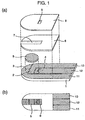
- Fig. 1 is an exploded perspective view and a top view of a biosensor in accordance with an exemplary embodiment of the present invention.
- Fig. 2 is an exploded perspective view and a top view showing an example of another biosensor in accordance with an exemplary embodiment of the present invention.
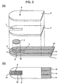
- Fig. 3 is an exploded perspective view and a top view showing an example in accordance with an exemplary embodiment of the present invention that has an air hole disposed within a specimen supply path..
- Fig. 4 is an exploded perspective view and a top view of a conventional biosensor.
- Fig. 5 is a drawing showing how a sample liquid is introduced into. a specimen supply path.
- Fig. 6 is a drawing showing how a sample liquid is introduced into a specimen supply path.
- Fig. 7 is a drawing showing how a sample liquid is sufficiently introduced into a specimen supply path.
-
- A biosensor in accordance with an exemplary embodiment of the present invention is demonstrated hereinafter with reference to Fig. 1. Specifically described herein is an enzyme sensor using an enzyme as a molecule-identifying element that specifically reacts with a particular component in a sample liquid.
- Fig. 1 is an exploded perspective view and a top view of a biosensor in accordance with this embodiment. In Fig. 1,
reference numeral 1 shows a first electrically insulating support. Formed on this first electricallyinsulating support 1 are measuringelectrode 2,counter electrode 3, and detectingelectrode 4 that are made of electrically conductive materials. - In this embodiment, what largely differs from a conventional biosensor is that detecting
electrode 4 having a predetermined shape is spaced fromcounter electrode 3 and measuringelectrode 2 by a predetermined distance inspecimen supply path 7. - This predetermined distance means a distance sufficient for the sample liquid to completely cover measuring
electrode 2 after the sample liquid is fed intospecimen supply path 7 before reaching detectingelectrode 4. This distance can be set arbitrarily according to the width of the. specimen supply path. - As for the predetermined shape, it is desirable that detecting
electrode 4 is shaped to lie nearest to the measuringelectrode 2 in the central portion ofspecimen supply path 7 and farther to the measuring electrode along the both edges ofspecimen supply path 7 than in the central portion thereof. These shapes include a V-shape, U-shape, and convex shape, and combinations thereof. Among these shapes, a V-shape is most preferable. - Because the detecting electrode has such a distance and shape, measurement of a sample liquid starts after the liquid has completely covered the measuring electrode. When an amount of sample liquid insufficient to completely cover measuring
electrode 2 is supplied as shown in Figs. 5 and 6, erroneous start of measurement can be prevented. Moreover, for the above-mentioned shape of detectingelectrode 4, the detecting electrode can be disposed nearer to the measuring electrode. Therefore, the amount of sample liquid necessary for the biosensor to measure can be reduced. - In the biosensor of Fig. 1, the space between measuring
electrode 2 and detectingelectrode 4 does not work as an electrode. However, as shown in Fig. 2, the space can be utilized as a part ofcounter electrode 3. - Moreover, detecting
electrode 4 described herein can be used as a part of the counter electrode, as well as working as an electrode for detecting an insufficient amount of analyte. - In the biosensor of Fig. 1, each of the electrodes is disposed on the first electrically insulating support. However, these electrodes can be divided and disposed not only on first electrically insulating
support 1 but also on second electrically insulatingsupport 8 opposed thereto. - Preferable materials of above-mentioned first electrically insulating
support 1 and second electrically insulatingsupport 8 include polyethylene terephthalate, polycarbonate, polyimide, and the like. - Electrically conductive materials constituting each electrode include single materials, such as noble metals (e.g. gold, platinum, and palladium) and carbon, and composite materials, such as carbon pastes and noble metal pastes.
- The electrically conductive layer can be formed on first electrically insulating
support 1 or second electrically insulatingsupport 8 easily by such a method as sputtering vapor deposition for the single materials, and by such a method as screen-printing for the composite materials. - Each of the electrodes can be formed separately by forming the electrically conductive layer on all or part of the surface of first electrically insulating
support 1 or second electrically insulatingsupport 8 by the above-mentioned sputtering vapor deposition and screen-printing and other methods, and subsequently providing slits therein using laser and other means. Similarly, the electrodes can be formed by screen-printing using a printing plate or mask having electrode patterns formed thereon in advance, sputtering vapor deposition, and other methods. - Formed on the electrodes formed in this manner is
reagent layer 5 containing an enzyme, electron transfer agent, hydrophilic polymer, and the like. - Examples of the usable enzyme include glucose oxidase, lactate oxidase, cholesterol oxidase, cholesterol esterase, uricase, ascorbate oxidase, bilirubin oxidase, glucose dehydrogenase, and lactate dehydrogenase. Examples of the usable electron transfer agent include p-benzoquinone and derivatives thereof, phenazine methosulfate, methylene blue, and ferrocene and derivatives thereof as well as potassium ferricyanide.
- Examples of the usable hydrophilic polymer include carboxymethyl cellulose, hydroxyethyl cellulose, hydroxypropyl cellulose, methyl cellulose, ethyl cellulose, ethyl hydroxyethyl cellulose, carboxymethyl ethyl cellulose, polyvinyl alcohol, polyvinyl pyrrolidone, polyamino acids (e.g. polylysine), polystyrene sulfonate, gelatin and derivatives thereof, acrylic acids and salts thereof, methacrylic acids and salts thereof, starch and derivatives thereof, maleic anhydrides and salts thereof, and agarose gel and derivatives thereof.
- Next, the first electrically insulating
support 1 and second electrically insulatingsupport 8 are bonded tospacer 6 having a cutout to formspecimen supply path 7 for receiving a sample liquid. - In order to reduce the amount of the sample liquid necessary for the biosensor to measure, it is desirable that
specimen supply path 7 has a width ranging from 0.5 to 2.0 mm andspacer 6 has a thickness (height) ranging from 0.05 to 0.3 mm. - Examples of the preferable material of
spacer 6 include polyethylene terephthalate, polycarbonate, polyimide, polybutylene terephthalate, polyamide, polyvinyl chloride, polyvinyliden chloride, polyimide, and nylon. - Alternatively, integrated second electrically insulating
support 8 andspacer 6 can be bonded to first electrically insulatingsupport 1 to formspecimen supply path 7. - The
reagent layer 5 can be placed in any position withinspecimen supply path 7 for receiving the sample liquid as well as on all or part of the surface of the electrodes, on condition that the reagent layer will not deteriorate the performance of the biosensor. - However, in order to realize quick detection of the sample liquid after the supply thereof, it is desirable that
reagent layer 5 exists on detectingelectrode 4 or in the vicinity thereof. - The supply of a sample liquid to a biosensor structured of such
specimen supply path 7 is realized by capillarity. In order to realize smooth supply of the sample liquid,air hole 9 for letting the air escape outside of the biosensor must be provided withinspecimen supply path 7. -
Air hole 9 can be disposed in any position withinspecimen supply path 7 on condition that the air hole will not hinder the supply of the sample liquid.Air hole 9 can be of any size that can let the air escape smoothly. When a small air hole is disposed within a specimen supply path,, the sample liquid is easily be lead along the edges of the. specimen supply path. Thus, the shape of the detecting electrode shown in Fig. 3 is most preferable. - In the biosensor of Fig. 3, arc slits are formed around the reagent dropping position. Specifically, by providing a wave-like arc slit 14 on the tip side of the sensor and slit 15 on the back side of the specimen supply path, propagation of the reagent is easily controlled in formation of
reagent layer 5. These arc slits are more effective in controlling the reagent than the arc slit disclosed in the above-mentioned PCT patent application. - In addition, rendering hydrophilic nature to the inner surface of the
specimen supply path 7 allows quicker and more accurate introduction of the sample liquid intospecimen supply path 7. - The methods of rendering hydrophilic nature include applying surface-active agent to first electrically insulating
support 1 or second electrically insulatingsupport 8 itself, or the surface thereof, and roughening the surface of the support material by sandblasting, electric-discharge machining, non-glare treatment, matting, chemical plating, or the like. - Described hereinafter is a system of checking for suction of an analyte when the content of a substrate in a sample liquid, i.e. the analyte, is determined using a biosensor of such a structure.
- First, a sample liquid is fed to the inlet of the specimen supply path while a constant voltage is applied between the counter electrode or the measuring electrode and the detecting electrode by a measuring device (not shown) coupled to the biosensor. The sample liquid is sucked into the specimen supply path by capillarity, passes over the counter electrode and the measuring electrode, and reaches the detecting electrode. Then, dissolution of the reagent layer starts. At this time, the measuring device detects electrical changes occurring between the counter electrode or the measuring electrode and the detecting electrode and starts measuring operation.
- In this embodiment, an enzyme sensor is described as an example of a biosensor. However, the present invention can similarly be applied to a biosensor that uses an antibody, microorganism, DNA, RNA, or the like as well as the enzyme as a molecule-identifying element specifically reacting with a particular component in the sample liquid.
- As mentioned above, the present invention can drastically improve the accuracy of detecting the introduction of a sample liquid into a specimen supply path using a detecting electrode. The present invention can also provide a high-performance biosensor causing less error of measurement. Furthermore, the sample liquid necessary for the biosensor to measure can be reduced. These advantages can provide a biosensor that has high user operability and can deal with a small amount of analyte.
Claims (10)
- A biosensor for quantifying a substrate contained in a sample liquid comprising:wherein said electrode system, said specimen supply path, and said reagent exist between said first electrically insulating support and said second electrically insulating support;a first electrically insulating support and a second electrically insulating support;an electrode system having at least a measuring electrode, a counter electrode, and a detecting electrode;a specimen supply path for introducing the sample liquid over said electrode system; anda reagent used for quantifying the substrate contained in the sample liquid;
wherein said electrode system is formed on one of all and part of an inner surface of at least one of said first electrically insulating support and said second electrically insulating support; and
wherein said detecting electrode is spaced from said measuring electrode by a distance sufficient for the sample liquid to sufficiently cover said measuring electrode before the sample liquid reaches said detecting electrode. - The biosensor as set forth in Claim 1, wherein said detecting electrode is shaped to project so that a central portion thereof is positioned nearest to said measuring electrode in said specimen supply path.
- The biosensor as set forth in Claim 1, wherein said detecting electrode is shaped so that a central portion thereof is positioned nearest to said measuring electrode and both edges thereof are positioned farther to said measuring electrode than the central portion in said. specimen supply path.
- The biosensor as set forth in Claim 1, wherein said detecting electrode is shaped to project in a direction of an inlet of said specimen supply path in a central position within said. specimen supply path.
- The biosensor as set forth in any one of Claims 2 through 4, wherein said detecting electrode positioned within said specimen supply path has one of a V-shape, a U-shape, and a convex shape.
- The biosensor as set forth in any one of Claims 1 through 5, wherein said specimen supply path has a width ranging from 0.5 to 2.0 mm.
- The biosensor as set forth in any one of Claims 1 through 6, wherein said specimen supply path has a height ranging from 0.05 to 0.3 mm.
- The biosensor as set forth in any one of Claims 1 through 7, wherein said electrode system is divided by providing a slit in an electrically conductive layer formed on one of all and part of an inner surface of at least one of said first electrically insulating support and said second electrically insulating support.
- The biosensor as set forth in Claim 8, wherein said slit is formed by machining the electrically conductive layer using laser.
- The biosensor as set forth in any one of Claims 1 through 9, wherein an air hole in communication with said specimen supply path is formed.
Priority Applications (1)
| Application Number | Priority Date | Filing Date | Title |
|---|---|---|---|
| EP10162536A EP2230508A1 (en) | 2001-04-16 | 2002-04-11 | Biosensor |
Applications Claiming Priority (3)
| Application Number | Priority Date | Filing Date | Title |
|---|---|---|---|
| JP2001116580 | 2001-04-16 | ||
| JP2001116580 | 2001-04-16 | ||
| PCT/JP2002/003600 WO2002086483A1 (en) | 2001-04-16 | 2002-04-11 | Biosensor |
Related Child Applications (1)
| Application Number | Title | Priority Date | Filing Date |
|---|---|---|---|
| EP10162536.6 Division-Into | 2010-05-11 |
Publications (3)
| Publication Number | Publication Date |
|---|---|
| EP1281955A1 true EP1281955A1 (en) | 2003-02-05 |
| EP1281955A4 EP1281955A4 (en) | 2009-07-22 |
| EP1281955B1 EP1281955B1 (en) | 2013-06-05 |
Family
ID=18967297
Family Applications (2)
| Application Number | Title | Priority Date | Filing Date |
|---|---|---|---|
| EP10162536A Withdrawn EP2230508A1 (en) | 2001-04-16 | 2002-04-11 | Biosensor |
| EP02718528.9A Expired - Lifetime EP1281955B1 (en) | 2001-04-16 | 2002-04-11 | Biosensor |
Family Applications Before (1)
| Application Number | Title | Priority Date | Filing Date |
|---|---|---|---|
| EP10162536A Withdrawn EP2230508A1 (en) | 2001-04-16 | 2002-04-11 | Biosensor |
Country Status (5)
| Country | Link |
|---|---|
| US (2) | US20030175946A1 (en) |
| EP (2) | EP2230508A1 (en) |
| JP (1) | JP4120400B2 (en) |
| CN (1) | CN100401050C (en) |
| WO (1) | WO2002086483A1 (en) |
Cited By (12)
| Publication number | Priority date | Publication date | Assignee | Title |
|---|---|---|---|---|
| WO2005008231A1 (en) * | 2003-06-20 | 2005-01-27 | Roche Diagnostics Gmbh | System and method for analyte measurement of biological fluids using dose sufficiency electrodes |
| EP1557662A1 (en) * | 2002-10-31 | 2005-07-27 | Matsushita Electric Industrial Co., Ltd. | Determination method for automatically identifying analyte liquid and standard solution for biosensor |
| US7695600B2 (en) | 2005-06-03 | 2010-04-13 | Hypoguard Limited | Test system |
| US7727467B2 (en) | 2003-06-20 | 2010-06-01 | Roche Diagnostics Operations, Inc. | Reagent stripe for test strip |
| US8071030B2 (en) | 2003-06-20 | 2011-12-06 | Roche Diagnostics Operations, Inc. | Test strip with flared sample receiving chamber |
| US8092668B2 (en) | 2004-06-18 | 2012-01-10 | Roche Diagnostics Operations, Inc. | System and method for quality assurance of a biosensor test strip |
| US8206565B2 (en) | 2003-06-20 | 2012-06-26 | Roche Diagnostics Operation, Inc. | System and method for coding information on a biosensor test strip |
| US8287703B2 (en) | 1999-10-04 | 2012-10-16 | Roche Diagnostics Operations, Inc. | Biosensor and method of making |
| US8298828B2 (en) | 2003-06-20 | 2012-10-30 | Roche Diagnostics Operations, Inc. | System and method for determining the concentration of an analyte in a sample fluid |
| US8506775B2 (en) | 2003-06-20 | 2013-08-13 | Roche Diagnostics Operations, Inc. | Devices and methods relating to electrochemical biosensors |
| EP2916126A1 (en) * | 2005-09-02 | 2015-09-09 | ARKRAY, Inc. | Analytical tool for for detecting sample supply condition |
| US9213015B2 (en) | 2011-02-23 | 2015-12-15 | Panasonic Healthcare Holdings Co., Ltd. | Biological sample measuring device |
Families Citing this family (22)
| Publication number | Priority date | Publication date | Assignee | Title |
|---|---|---|---|---|
| US8071384B2 (en) | 1997-12-22 | 2011-12-06 | Roche Diagnostics Operations, Inc. | Control and calibration solutions and methods for their use |
| US7073246B2 (en) | 1999-10-04 | 2006-07-11 | Roche Diagnostics Operations, Inc. | Method of making a biosensor |
| US6814844B2 (en) * | 2001-08-29 | 2004-11-09 | Roche Diagnostics Corporation | Biosensor with code pattern |
| US7645373B2 (en) | 2003-06-20 | 2010-01-12 | Roche Diagnostic Operations, Inc. | System and method for coding information on a biosensor test strip |
| US8679853B2 (en) | 2003-06-20 | 2014-03-25 | Roche Diagnostics Operations, Inc. | Biosensor with laser-sealed capillary space and method of making |
| US7488601B2 (en) | 2003-06-20 | 2009-02-10 | Roche Diagnostic Operations, Inc. | System and method for determining an abused sensor during analyte measurement |
| US8058077B2 (en) | 2003-06-20 | 2011-11-15 | Roche Diagnostics Operations, Inc. | Method for coding information on a biosensor test strip |
| US7645421B2 (en) | 2003-06-20 | 2010-01-12 | Roche Diagnostics Operations, Inc. | System and method for coding information on a biosensor test strip |
| US7718439B2 (en) | 2003-06-20 | 2010-05-18 | Roche Diagnostics Operations, Inc. | System and method for coding information on a biosensor test strip |
| US7622026B2 (en) * | 2004-03-02 | 2009-11-24 | Panasonic Corporation | Biosensor |
| WO2007121121A2 (en) * | 2006-04-11 | 2007-10-25 | Home Diagnostics Inc. | Laminated biosensor and its manufacturing method |
| KR100829400B1 (en) * | 2006-11-30 | 2008-05-15 | 주식회사 인포피아 | Bio-sensor |
| US7943022B2 (en) * | 2007-09-04 | 2011-05-17 | Lifescan, Inc. | Analyte test strip with improved reagent deposition |
| TWI460423B (en) | 2007-10-31 | 2014-11-11 | Arkray Inc | Biosensor and its manufacturing method |
| WO2009057793A1 (en) * | 2007-10-31 | 2009-05-07 | Arkray, Inc. | Analysis tool, analyzer, sample shortage detection method, and sample analysis method |
| CN103487476B (en) * | 2009-05-25 | 2015-09-09 | 利多(香港)有限公司 | Biology sensor |
| KR20130018727A (en) * | 2010-03-03 | 2013-02-25 | 니폰 가야꾸 가부시끼가이샤 | Detection device |
| US8940141B2 (en) | 2010-05-19 | 2015-01-27 | Lifescan Scotland Limited | Analytical test strip with an electrode having electrochemically active and inert areas of a predetermined size and distribution |
| EP3454056A4 (en) * | 2016-02-25 | 2019-06-26 | PHC Holdings Corporation | Biosensor |
| DE102018114206A1 (en) | 2018-06-14 | 2019-12-19 | RUHR-UNIVERSITäT BOCHUM | Biosensor and method for producing one |
| WO2022100617A1 (en) * | 2020-11-11 | 2022-05-19 | 利多(香港)有限公司 | Biosensor |
| CN117092183A (en) * | 2022-05-18 | 2023-11-21 | 利多(香港)有限公司 | Biosensor and preparation method thereof |
Citations (3)
| Publication number | Priority date | Publication date | Assignee | Title |
|---|---|---|---|---|
| JPS61294351A (en) * | 1985-06-21 | 1986-12-25 | Matsushita Electric Ind Co Ltd | Biosensor |
| EP0537761A2 (en) * | 1991-10-18 | 1993-04-21 | Matsushita Electric Industrial Co., Ltd. | A biosensor and a method for measuring a concentration of a substrate in a sample |
| US6004441A (en) * | 1996-01-10 | 1999-12-21 | Matsushita Electric Industrial Co., Ltd. | Biosensor |
Family Cites Families (24)
| Publication number | Priority date | Publication date | Assignee | Title |
|---|---|---|---|---|
| US4172770A (en) * | 1978-03-27 | 1979-10-30 | Technicon Instruments Corporation | Flow-through electrochemical system analytical method |
| JPH0658338B2 (en) * | 1988-05-18 | 1994-08-03 | 松下電器産業株式会社 | Biosensor |
| WO1989009397A1 (en) * | 1988-03-31 | 1989-10-05 | Matsushita Electric Industrial Co., Ltd. | Biosensor and process for its production |
| JPH0375552A (en) * | 1989-08-17 | 1991-03-29 | Omron Corp | Enzyme electrode |
| JPH0820412B2 (en) * | 1990-07-20 | 1996-03-04 | 松下電器産業株式会社 | Quantitative analysis method and device using disposable sensor |
| US5192415A (en) * | 1991-03-04 | 1993-03-09 | Matsushita Electric Industrial Co., Ltd. | Biosensor utilizing enzyme and a method for producing the same |
| JP2960265B2 (en) * | 1991-10-18 | 1999-10-06 | 松下電器産業株式会社 | Biosensor and measurement method using the same |
| JP3084877B2 (en) * | 1992-01-21 | 2000-09-04 | 松下電器産業株式会社 | Manufacturing method of glucose sensor |
| JP3189416B2 (en) * | 1992-09-25 | 2001-07-16 | 松下電器産業株式会社 | Liquid component measuring device |
| JP3149597B2 (en) * | 1993-02-03 | 2001-03-26 | 松下電器産業株式会社 | Body fluid component measurement device |
| US5582697A (en) | 1995-03-17 | 1996-12-10 | Matsushita Electric Industrial Co., Ltd. | Biosensor, and a method and a device for quantifying a substrate in a sample liquid using the same |
| JP3102627B2 (en) * | 1995-03-17 | 2000-10-23 | 松下電器産業株式会社 | Biosensor, quantitative method and quantitative device using the same |
| JP3437016B2 (en) * | 1995-07-31 | 2003-08-18 | 松下電器産業株式会社 | Biosensor and method of quantifying substrate using the same |
| US6309526B1 (en) * | 1997-07-10 | 2001-10-30 | Matsushita Electric Industrial Co., Ltd. | Biosensor |
| JP3267936B2 (en) * | 1998-08-26 | 2002-03-25 | 松下電器産業株式会社 | Biosensor |
| US6338790B1 (en) * | 1998-10-08 | 2002-01-15 | Therasense, Inc. | Small volume in vitro analyte sensor with diffusible or non-leachable redox mediator |
| US6258229B1 (en) * | 1999-06-02 | 2001-07-10 | Handani Winarta | Disposable sub-microliter volume sensor and method of making |
| CA2305922C (en) * | 1999-08-02 | 2005-09-20 | Bayer Corporation | Improved electrochemical sensor design |
| JP4226756B2 (en) * | 1999-11-15 | 2009-02-18 | パナソニック株式会社 | Biosensor, quantitative method and quantitative apparatus using the same |
| JP4184572B2 (en) * | 2000-04-27 | 2008-11-19 | 松下電器産業株式会社 | Biosensor |
| EP2889611B1 (en) * | 1999-11-15 | 2019-09-04 | PHC Holdings Corporation | Biosensor and measurement apparatus. |
| JP4061816B2 (en) * | 2000-04-27 | 2008-03-19 | 松下電器産業株式会社 | Biosensor |
| JP2001330581A (en) * | 2000-05-19 | 2001-11-30 | Matsushita Electric Ind Co Ltd | Substrate concentration determination method |
| JP4576672B2 (en) * | 2000-06-15 | 2010-11-10 | パナソニック株式会社 | Biosensor |
-
2002
- 2002-04-11 WO PCT/JP2002/003600 patent/WO2002086483A1/en active Application Filing
- 2002-04-11 US US10/297,888 patent/US20030175946A1/en not_active Abandoned
- 2002-04-11 EP EP10162536A patent/EP2230508A1/en not_active Withdrawn
- 2002-04-11 EP EP02718528.9A patent/EP1281955B1/en not_active Expired - Lifetime
- 2002-04-11 JP JP2002583962A patent/JP4120400B2/en not_active Expired - Lifetime
- 2002-04-11 CN CNB028011406A patent/CN100401050C/en not_active Expired - Lifetime
-
2010
- 2010-06-25 US US12/823,676 patent/US8475638B2/en not_active Expired - Lifetime
Patent Citations (3)
| Publication number | Priority date | Publication date | Assignee | Title |
|---|---|---|---|---|
| JPS61294351A (en) * | 1985-06-21 | 1986-12-25 | Matsushita Electric Ind Co Ltd | Biosensor |
| EP0537761A2 (en) * | 1991-10-18 | 1993-04-21 | Matsushita Electric Industrial Co., Ltd. | A biosensor and a method for measuring a concentration of a substrate in a sample |
| US6004441A (en) * | 1996-01-10 | 1999-12-21 | Matsushita Electric Industrial Co., Ltd. | Biosensor |
Non-Patent Citations (1)
| Title |
|---|
| See also references of WO02086483A1 * |
Cited By (24)
| Publication number | Priority date | Publication date | Assignee | Title |
|---|---|---|---|---|
| US8287703B2 (en) | 1999-10-04 | 2012-10-16 | Roche Diagnostics Operations, Inc. | Biosensor and method of making |
| US8551308B2 (en) | 1999-10-04 | 2013-10-08 | Roche Diagnostics Operations, Inc. | Biosensor and method of making |
| EP1557662A1 (en) * | 2002-10-31 | 2005-07-27 | Matsushita Electric Industrial Co., Ltd. | Determination method for automatically identifying analyte liquid and standard solution for biosensor |
| EP1557662A4 (en) * | 2002-10-31 | 2009-06-24 | Panasonic Corp | Determination method for automatically identifying analyte liquid and standard solution for biosensor |
| US8142721B2 (en) | 2003-06-20 | 2012-03-27 | Roche Diagnostics Operations, Inc. | Test strip with slot vent opening |
| US8206565B2 (en) | 2003-06-20 | 2012-06-26 | Roche Diagnostics Operation, Inc. | System and method for coding information on a biosensor test strip |
| US7829023B2 (en) | 2003-06-20 | 2010-11-09 | Roche Diagnostics Operations, Inc. | Test strip with vent opening |
| US7879618B2 (en) | 2003-06-20 | 2011-02-01 | Roche Diagnostics Operations, Inc. | Method and reagent for producing narrow, homogenous reagent strips |
| US7892849B2 (en) | 2003-06-20 | 2011-02-22 | Roche Diagnostics Operations, Inc. | Reagent stripe for test strip |
| US8071030B2 (en) | 2003-06-20 | 2011-12-06 | Roche Diagnostics Operations, Inc. | Test strip with flared sample receiving chamber |
| US8586373B2 (en) | 2003-06-20 | 2013-11-19 | Roche Diagnostics Operations, Inc. | System and method for determining the concentration of an analyte in a sample fluid |
| US8119414B2 (en) | 2003-06-20 | 2012-02-21 | Roche Diagnostics Operations, Inc. | Test strip with slot vent opening |
| WO2005008231A1 (en) * | 2003-06-20 | 2005-01-27 | Roche Diagnostics Gmbh | System and method for analyte measurement of biological fluids using dose sufficiency electrodes |
| US7749437B2 (en) | 2003-06-20 | 2010-07-06 | Roche Diagnostics Operations, Inc. | Method and reagent for producing narrow, homogenous reagent stripes |
| US8211379B2 (en) | 2003-06-20 | 2012-07-03 | Roche Diagnostics Operations, Inc. | Test strip with slot vent opening |
| US8222044B2 (en) | 2003-06-20 | 2012-07-17 | Roche Diagnostics Operations, Inc. | Test strip with flared sample receiving chamber |
| US7727467B2 (en) | 2003-06-20 | 2010-06-01 | Roche Diagnostics Operations, Inc. | Reagent stripe for test strip |
| US8298828B2 (en) | 2003-06-20 | 2012-10-30 | Roche Diagnostics Operations, Inc. | System and method for determining the concentration of an analyte in a sample fluid |
| US8506775B2 (en) | 2003-06-20 | 2013-08-13 | Roche Diagnostics Operations, Inc. | Devices and methods relating to electrochemical biosensors |
| US8092668B2 (en) | 2004-06-18 | 2012-01-10 | Roche Diagnostics Operations, Inc. | System and method for quality assurance of a biosensor test strip |
| US7695600B2 (en) | 2005-06-03 | 2010-04-13 | Hypoguard Limited | Test system |
| EP2916126A1 (en) * | 2005-09-02 | 2015-09-09 | ARKRAY, Inc. | Analytical tool for for detecting sample supply condition |
| US9213015B2 (en) | 2011-02-23 | 2015-12-15 | Panasonic Healthcare Holdings Co., Ltd. | Biological sample measuring device |
| US10241069B2 (en) | 2011-02-23 | 2019-03-26 | Phc Holdings Corporation | Biological sample measuring device |
Also Published As
| Publication number | Publication date |
|---|---|
| EP1281955B1 (en) | 2013-06-05 |
| US20100258438A1 (en) | 2010-10-14 |
| EP2230508A1 (en) | 2010-09-22 |
| US8475638B2 (en) | 2013-07-02 |
| EP1281955A4 (en) | 2009-07-22 |
| JP4120400B2 (en) | 2008-07-16 |
| CN1461410A (en) | 2003-12-10 |
| WO2002086483A1 (en) | 2002-10-31 |
| CN100401050C (en) | 2008-07-09 |
| JPWO2002086483A1 (en) | 2004-08-12 |
| US20030175946A1 (en) | 2003-09-18 |
Similar Documents
| Publication | Publication Date | Title |
|---|---|---|
| US8475638B2 (en) | Biosensor | |
| US9459229B2 (en) | Electrochemical test sensor | |
| US9290839B2 (en) | Method of making, and, analyte sensor | |
| JP4501793B2 (en) | Biosensor | |
| JPH1142098A (en) | Quantitative determination of substrate | |
| JPWO2004102176A1 (en) | Sensor | |
| JP2007147638A (en) | Amperometric titration biosensor test strip | |
| JP4061816B2 (en) | Biosensor | |
| JP4639465B2 (en) | Biosensor | |
| US10190146B2 (en) | Method of correcting for oxygen effect | |
| EP2348308B1 (en) | Biosensor | |
| JPH11344461A (en) | Biosensor | |
| Tokunaga et al. | Biosensor | |
| JPH10282038A (en) | Biosensor |
Legal Events
| Date | Code | Title | Description |
|---|---|---|---|
| PUAI | Public reference made under article 153(3) epc to a published international application that has entered the european phase |
Free format text: ORIGINAL CODE: 0009012 |
|
| 17P | Request for examination filed |
Effective date: 20021205 |
|
| AK | Designated contracting states |
Designated state(s): AT BE CH CY DE DK ES FI FR GB GR IE IT LI LU MC NL PT SE TR |
|
| RAP1 | Party data changed (applicant data changed or rights of an application transferred) |
Owner name: PANASONIC CORPORATION |
|
| A4 | Supplementary search report drawn up and despatched |
Effective date: 20090623 |
|
| 17Q | First examination report despatched |
Effective date: 20091029 |
|
| RBV | Designated contracting states (corrected) |
Designated state(s): DE FR GB IT |
|
| REG | Reference to a national code |
Ref country code: DE Ref legal event code: R079 Ref document number: 60245067 Country of ref document: DE Free format text: PREVIOUS MAIN CLASS: G01N0027327000 Ipc: C12Q0001000000 |
|
| GRAP | Despatch of communication of intention to grant a patent |
Free format text: ORIGINAL CODE: EPIDOSNIGR1 |
|
| RIC1 | Information provided on ipc code assigned before grant |
Ipc: G01N 27/327 20060101ALI20121031BHEP Ipc: C12Q 1/00 20060101AFI20121031BHEP |
|
| GRAS | Grant fee paid |
Free format text: ORIGINAL CODE: EPIDOSNIGR3 |
|
| GRAA | (expected) grant |
Free format text: ORIGINAL CODE: 0009210 |
|
| AK | Designated contracting states |
Kind code of ref document: B1 Designated state(s): DE FR GB IT |
|
| REG | Reference to a national code |
Ref country code: GB Ref legal event code: FG4D |
|
| REG | Reference to a national code |
Ref country code: DE Ref legal event code: R096 Ref document number: 60245067 Country of ref document: DE Effective date: 20130725 |
|
| REG | Reference to a national code |
Ref country code: DE Ref legal event code: R082 Ref document number: 60245067 Country of ref document: DE Representative=s name: GRUENECKER, KINKELDEY, STOCKMAIR & SCHWANHAEUS, DE |
|
| REG | Reference to a national code |
Ref country code: GB Ref legal event code: 732E Free format text: REGISTERED BETWEEN 20140313 AND 20140319 |
|
| PLBE | No opposition filed within time limit |
Free format text: ORIGINAL CODE: 0009261 |
|
| STAA | Information on the status of an ep patent application or granted ep patent |
Free format text: STATUS: NO OPPOSITION FILED WITHIN TIME LIMIT |
|
| REG | Reference to a national code |
Ref country code: DE Ref legal event code: R081 Ref document number: 60245067 Country of ref document: DE Owner name: PANASONIC CORPORATION, JP Free format text: FORMER OWNER: PANASONIC CORPORATION, KADOMA-SHI, JP Effective date: 20140324 Ref country code: DE Ref legal event code: R081 Ref document number: 60245067 Country of ref document: DE Owner name: PANASONIC CORPORATION, JP Free format text: FORMER OWNER: PANASONIC HEALTHCARE CO., LTD., TOON-SHI, JP Effective date: 20140404 Ref country code: DE Ref legal event code: R082 Ref document number: 60245067 Country of ref document: DE Representative=s name: GRUENECKER, KINKELDEY, STOCKMAIR & SCHWANHAEUS, DE Effective date: 20140324 Ref country code: DE Ref legal event code: R081 Ref document number: 60245067 Country of ref document: DE Owner name: PANASONIC CORPORATION, JP Free format text: FORMER OWNER: MATSUSHITA ELECTRIC INDUSTRIAL CO., LTD., KADOMA-SHI, JP Effective date: 20130605 Ref country code: DE Ref legal event code: R082 Ref document number: 60245067 Country of ref document: DE Representative=s name: GRUENECKER, KINKELDEY, STOCKMAIR & SCHWANHAEUS, DE Effective date: 20140404 Ref country code: DE Ref legal event code: R081 Ref document number: 60245067 Country of ref document: DE Owner name: PANASONIC HEALTHCARE HOLDINGS CO., LTD., JP Free format text: FORMER OWNER: PANASONIC HEALTHCARE CO., LTD., TOON-SHI, EHIME, JP Effective date: 20140404 Ref country code: DE Ref legal event code: R081 Ref document number: 60245067 Country of ref document: DE Owner name: PANASONIC HEALTHCARE HOLDINGS CO., LTD., JP Free format text: FORMER OWNER: MATSUSHITA ELECTRIC INDUSTRIAL CO., LTD., KADOMA-SHI, OSAKA, JP Effective date: 20130605 Ref country code: DE Ref legal event code: R081 Ref document number: 60245067 Country of ref document: DE Owner name: PANASONIC HEALTHCARE HOLDINGS CO., LTD., JP Free format text: FORMER OWNER: PANASONIC CORPORATION, KADOMA-SHI, OSAKA, JP Effective date: 20140324 Ref country code: DE Ref legal event code: R082 Ref document number: 60245067 Country of ref document: DE Representative=s name: GRUENECKER PATENT- UND RECHTSANWAELTE PARTG MB, DE Effective date: 20140324 Ref country code: DE Ref legal event code: R082 Ref document number: 60245067 Country of ref document: DE Representative=s name: GRUENECKER PATENT- UND RECHTSANWAELTE PARTG MB, DE Effective date: 20140404 |
|
| 26N | No opposition filed |
Effective date: 20140306 |
|
| REG | Reference to a national code |
Ref country code: DE Ref legal event code: R097 Ref document number: 60245067 Country of ref document: DE Effective date: 20140306 |
|
| REG | Reference to a national code |
Ref country code: GB Ref legal event code: 732E Free format text: REGISTERED BETWEEN 20140814 AND 20140820 |
|
| REG | Reference to a national code |
Ref country code: DE Ref legal event code: R082 Ref document number: 60245067 Country of ref document: DE Representative=s name: GRUENECKER, KINKELDEY, STOCKMAIR & SCHWANHAEUS, DE |
|
| REG | Reference to a national code |
Ref country code: FR Ref legal event code: CA Effective date: 20140827 Ref country code: FR Ref legal event code: TP Owner name: PANASONIC HEALTHCARE HOLDINGS CO., LTD., JP Effective date: 20140827 |
|
| REG | Reference to a national code |
Ref country code: GB Ref legal event code: 732E Free format text: REGISTERED BETWEEN 20141002 AND 20141008 |
|
| REG | Reference to a national code |
Ref country code: DE Ref legal event code: R082 Ref document number: 60245067 Country of ref document: DE Representative=s name: GRUENECKER, KINKELDEY, STOCKMAIR & SCHWANHAEUS, DE Effective date: 20140925 Ref country code: DE Ref legal event code: R081 Ref document number: 60245067 Country of ref document: DE Owner name: PANASONIC HEALTHCARE HOLDINGS CO., LTD., JP Free format text: FORMER OWNER: PANASONIC CORPORATION, KADOMA-SHI, OSAKA, JP Effective date: 20140925 Ref country code: DE Ref legal event code: R082 Ref document number: 60245067 Country of ref document: DE Representative=s name: GRUENECKER PATENT- UND RECHTSANWAELTE PARTG MB, DE Effective date: 20140925 |
|
| REG | Reference to a national code |
Ref country code: FR Ref legal event code: TP Owner name: PANASONIC HEALTHCARE HOLDINGS CO., LTD., JP Effective date: 20141008 |
|
| REG | Reference to a national code |
Ref country code: FR Ref legal event code: CD Owner name: PANASONIC HEALTHCARE HOLDINGS CO., LTD., JP Effective date: 20141218 Ref country code: FR Ref legal event code: TP Owner name: PANASONIC HEALTHCARE HOLDINGS CO., LTD., JP Effective date: 20141218 Ref country code: FR Ref legal event code: CA Effective date: 20141218 |
|
| REG | Reference to a national code |
Ref country code: FR Ref legal event code: PLFP Year of fee payment: 15 |
|
| REG | Reference to a national code |
Ref country code: FR Ref legal event code: PLFP Year of fee payment: 16 |
|
| REG | Reference to a national code |
Ref country code: FR Ref legal event code: PLFP Year of fee payment: 17 |
|
| REG | Reference to a national code |
Ref country code: DE Ref legal event code: R082 Ref document number: 60245067 Country of ref document: DE Representative=s name: GRUENECKER PATENT- UND RECHTSANWAELTE PARTG MB, DE Ref country code: DE Ref legal event code: R081 Ref document number: 60245067 Country of ref document: DE Owner name: PHC HOLDINGS CORP., JP Free format text: FORMER OWNER: PANASONIC HEALTHCARE HOLDINGS CO., LTD., TOKIO, JP |
|
| PGFP | Annual fee paid to national office [announced via postgrant information from national office to epo] |
Ref country code: FR Payment date: 20210310 Year of fee payment: 20 Ref country code: IT Payment date: 20210310 Year of fee payment: 20 |
|
| PGFP | Annual fee paid to national office [announced via postgrant information from national office to epo] |
Ref country code: GB Payment date: 20210318 Year of fee payment: 20 |
|
| PGFP | Annual fee paid to national office [announced via postgrant information from national office to epo] |
Ref country code: DE Payment date: 20210316 Year of fee payment: 20 |
|
| REG | Reference to a national code |
Ref country code: DE Ref legal event code: R071 Ref document number: 60245067 Country of ref document: DE |
|
| REG | Reference to a national code |
Ref country code: GB Ref legal event code: PE20 Expiry date: 20220410 |
|
| PG25 | Lapsed in a contracting state [announced via postgrant information from national office to epo] |
Ref country code: GB Free format text: LAPSE BECAUSE OF EXPIRATION OF PROTECTION Effective date: 20220410 |