EP1281839A2 - Walzenschieber-Anordnung, insbesondere zur Ladungssteuerung einer Brennkraftmaschine - Google Patents
Walzenschieber-Anordnung, insbesondere zur Ladungssteuerung einer Brennkraftmaschine Download PDFInfo
- Publication number
- EP1281839A2 EP1281839A2 EP02013352A EP02013352A EP1281839A2 EP 1281839 A2 EP1281839 A2 EP 1281839A2 EP 02013352 A EP02013352 A EP 02013352A EP 02013352 A EP02013352 A EP 02013352A EP 1281839 A2 EP1281839 A2 EP 1281839A2
- Authority
- EP
- European Patent Office
- Prior art keywords
- slide
- roller
- ring
- valve arrangement
- channel
- Prior art date
- Legal status (The legal status is an assumption and is not a legal conclusion. Google has not performed a legal analysis and makes no representation as to the accuracy of the status listed.)
- Granted
Links
- 238000002485 combustion reaction Methods 0.000 title claims description 5
- 238000007789 sealing Methods 0.000 claims description 17
- 238000011144 upstream manufacturing Methods 0.000 claims description 6
- 229920001971 elastomer Polymers 0.000 claims description 3
- 239000000806 elastomer Substances 0.000 claims description 3
- 230000002411 adverse Effects 0.000 description 1
- 238000005452 bending Methods 0.000 description 1
- 230000000903 blocking effect Effects 0.000 description 1
Images

Classifications
-
- F—MECHANICAL ENGINEERING; LIGHTING; HEATING; WEAPONS; BLASTING
- F01—MACHINES OR ENGINES IN GENERAL; ENGINE PLANTS IN GENERAL; STEAM ENGINES
- F01L—CYCLICALLY OPERATING VALVES FOR MACHINES OR ENGINES
- F01L7/00—Rotary or oscillatory slide valve-gear or valve arrangements
- F01L7/16—Sealing or packing arrangements specially therefor
-
- F—MECHANICAL ENGINEERING; LIGHTING; HEATING; WEAPONS; BLASTING
- F01—MACHINES OR ENGINES IN GENERAL; ENGINE PLANTS IN GENERAL; STEAM ENGINES
- F01L—CYCLICALLY OPERATING VALVES FOR MACHINES OR ENGINES
- F01L1/00—Valve-gear or valve arrangements, e.g. lift-valve gear
- F01L1/44—Multiple-valve gear or arrangements, not provided for in preceding subgroups, e.g. with lift and different valves
- F01L1/443—Multiple-valve gear or arrangements, not provided for in preceding subgroups, e.g. with lift and different valves comprising a lift valve and at least one rotary valve
-
- F—MECHANICAL ENGINEERING; LIGHTING; HEATING; WEAPONS; BLASTING
- F02—COMBUSTION ENGINES; HOT-GAS OR COMBUSTION-PRODUCT ENGINE PLANTS
- F02D—CONTROLLING COMBUSTION ENGINES
- F02D9/00—Controlling engines by throttling air or fuel-and-air induction conduits or exhaust conduits
- F02D9/08—Throttle valves specially adapted therefor; Arrangements of such valves in conduits
- F02D9/12—Throttle valves specially adapted therefor; Arrangements of such valves in conduits having slidably-mounted valve members; having valve members movable longitudinally of conduit
- F02D9/16—Throttle valves specially adapted therefor; Arrangements of such valves in conduits having slidably-mounted valve members; having valve members movable longitudinally of conduit the members being rotatable
-
- F—MECHANICAL ENGINEERING; LIGHTING; HEATING; WEAPONS; BLASTING
- F02—COMBUSTION ENGINES; HOT-GAS OR COMBUSTION-PRODUCT ENGINE PLANTS
- F02D—CONTROLLING COMBUSTION ENGINES
- F02D9/00—Controlling engines by throttling air or fuel-and-air induction conduits or exhaust conduits
- F02D9/02—Controlling engines by throttling air or fuel-and-air induction conduits or exhaust conduits concerning induction conduits
Definitions
- the invention relates to a preamble of claim 1 Roller valve arrangement, in particular for charge control of an internal combustion engine, the one rotatably arranged in a housing with play Roller slide essentially comprises averaged transversely to the axis of rotation arranged through channel, and an upstream of the through channel in a recess of the housing arranged, an inflow channel in sections delimiting slide ring for slidably tight support on the outer contour of the roller valve, the slide ring in the recess with the interposition a sealing element is movably arranged.
- Such a roller valve arrangement is, for example, from DE 198 15 739 A1 known, the sliding ring in the recess of the housing with interposition an O-ring is movably arranged as a sealing element. At this seal sealed against the inflow channel acts in particular in a position of the roller valve closing the inflow channel this downstream suction vacuum via the running clearance or the circumferential gap between the roller valve and the housing. The therefore with suction vacuum piston ring acted upon by an overpressure in the inflow channel is thereby adversely opposed to any rotation of the plunger the outer circumference pressed tight.
- the invention is based on the object, the roller valve arrangement to improve that the slide ring essentially only in the locked position of the roller valve lies tight against the inflow channel.
- a structurally advantageous embodiment of the arrangement is achieved in that the Recess in the housing is designed as a stepped bore with a roller valve facing bore section of small diameter and that the slide ring in the area of the large diameter bore section Has radial flange, between the shoulder of the stepped bore and the Radial flange a device for controlled lifting of the slide ring from the roller valve is arranged.
- a spring element serves as a device.
- This can be a ring wave spring or a plate spring or a ring spring made of an elastomer.
- the sealing element be a lip sealing ring is in the bore portion of large diameter of the housing recess press-in retaining ring arranged a radially inward sealing lip is that cooperates closely with the upstream end face of the slide ring.
- this lip sealing ring is that the ring-shaped sealing lip when moving of the sliding ring by bending deformation follows the moving sliding ring smallest possible friction of the sealing lip on the face of the slide ring.
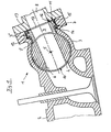
- a roller valve arrangement 1 for charge control of a not shown Internal combustion engine 2 includes one with play in a housing 3 rotatably arranged roller slide with a transverse to the axis of rotation 5 in essentially averaged through channel 6. Upstream of the through channel 6 is an inflow channel 8 in a recess 7 of the housing 3 Sectionally delimiting slide ring 9 for slidably tight support on the Outer contour 10 of the roller valve 4 arranged, the sliding ring 9 in the Recess 7 arranged movably with the interposition of a sealing element 11 is.
- the recess 7 in the housing 3 is one Stepped bore designed with a bore section facing the roller valve 4 7 'of small diameter, the sliding ring 9 in the region of the bore section 7 "of large diameter has a radial flange 13. It can also be seen from the drawing that between paragraph 14 of the stepped bore 7 and the radial flange 13 a device 12 for controlled lifting the slide ring 9 is arranged by the roller valve 4.
- a small-sized device 12 is achieved by means of a spring element.
- This can be designed as an annular wave spring or as a plate spring. Can continue the device or the spring element 12 also as an annular spring from a Be designed elastomer.
- a sealing element 11 Lip sealing ring is provided, on the large in the bore portion 7 " Diameter of the housing recess 7 press-in retaining ring 15 a radial inwardly directed sealing lip 16 is arranged, with the upstream end face 17 of the slide ring 9 via a flexible deformation with low friction works closely together.
Landscapes
- Engineering & Computer Science (AREA)
- Mechanical Engineering (AREA)
- General Engineering & Computer Science (AREA)
- Chemical & Material Sciences (AREA)
- Combustion & Propulsion (AREA)
- Sealing With Elastic Sealing Lips (AREA)
- Sealing Devices (AREA)
- Sliding Valves (AREA)
Abstract
Description
- Fig. 1
- eine Walzenschieber-Anordung zur Ladungssteuerung einer Brennkraftmaschine mit einem vom Walzenschieber mittels Federkraft abgehobenen Gleitring,
- Fig. 2
- die Anordnung nach Fig. 1 in Sperrstellung des Walzenschiebers mit an dessen Außenumfang angeschlagenem Gleitring.
Claims (6)
- Walzenschieber-Anordnung, insbesondere zur Ladungssteuerung einer Brennkraftmaschine, umfassend einen in einem Gehäuse (3) spielbehaftet drehbeweglich angeordneten Walzenschieber (4) mit einem quer zur Drehachse (5) im wesentlichen gemittelt angeordneten Durchgangskanal (6), unddadurch gekennzeichnet,einen stromauf des Durchgangskanals (6) in einer Ausnehmung (7) des Gehäuses (3) angeordneten, einen Zuströmkanal (8) abschnittsweise begrenzenden Gleitring (9) zur gleitbeweglich dichten Auflage auf der Außenkontur (10) des Walzenschiebers (4), wobeider Gleitring (9) in der Ausnehmung (7) unter Zwischenschaltung eines Dichtelementes (11) beweglich angeordnet ist,dass der Gleitring (9) bei den Zuströmkanal (8) offen steuernden Durchgangskanal (6) mittels einer Einrichtung (12) von der Außenkontur (10) des Walzenschiebers (4) entfernt bzw. abgehoben angeordnet ist.
- Walzenschieber-Anordnung nach Anspruch 1, dadurch gekennzeichnet,dass die Ausnehmung (7) im Gehäuse (3) als eine Stufenbohrung gestaltet ist mit einem dem Walzenschieber (4) zugewandten Bohrungsabschnitt (7') von kleinem Durchmesser, unddass der Gleitring (9) im Bereich des Bohrungsabschnittes (7") von großem Durchmesser einen Radialflansch (13) aufweist, wobeizwischen dem Absatz (14) der Stufenbohrung (7) und dem Radialflansch (13) eine Einrichtung (12) zum gesteuerten Abheben des Gleitringes (9) vom Walzenschieber (4) angeordnet ist.
- Walzenschieber-Anordnung nach Anspruch 2, dadurch gekennzeichnet, dass als Einrichtung (12) ein Federelement dient.
- Walzenschieber-Anordnung nach Anspruch 2 und 3, dadurch gekennzeichnet, dass als Federelement (12) eine Ring-Wellfeder oder eine Tellerfeder dient.
- Walzenschieber-Anordnung nach Anspruch 2 und 3, dadurch gekennzeichnet, dass das Federelement (12) eine Ringfeder aus einem Elastomer ist.
- Walzenschieber-Anordnung nach einem oder mehreren der Ansprüche 1 bis 5, dadurch gekennzeichnet,dass das Dichtelement (11) ein Lippen-Dichtring ist, andessen in den Bohrungsabschnitt (7") von großem Durchmesser der Gehäuse-Ausnehmung (7) einpressbaren Haltering (15) eine radial einwärts gerichtete Dichtlippe (16) angeordnet ist, diemit der zuströmseitigen Stirnseite (17) des Gleitringes (9) dicht zusammenwirkt.
Applications Claiming Priority (2)
| Application Number | Priority Date | Filing Date | Title |
|---|---|---|---|
| DE2001137251 DE10137251A1 (de) | 2001-07-31 | 2001-07-31 | Walzenschieber-Anordnung, insbesondere zur Ladungssteuerung einer Brennkraftmaschine |
| DE10137251 | 2001-07-31 |
Publications (3)
| Publication Number | Publication Date |
|---|---|
| EP1281839A2 true EP1281839A2 (de) | 2003-02-05 |
| EP1281839A3 EP1281839A3 (de) | 2003-07-02 |
| EP1281839B1 EP1281839B1 (de) | 2006-10-25 |
Family
ID=7693698
Family Applications (1)
| Application Number | Title | Priority Date | Filing Date |
|---|---|---|---|
| EP20020013352 Expired - Lifetime EP1281839B1 (de) | 2001-07-31 | 2002-06-19 | Walzenschieber-Anordnung, insbesondere zur Ladungssteuerung einer Brennkraftmaschine |
Country Status (2)
| Country | Link |
|---|---|
| EP (1) | EP1281839B1 (de) |
| DE (2) | DE10137251A1 (de) |
Cited By (4)
| Publication number | Priority date | Publication date | Assignee | Title |
|---|---|---|---|---|
| EP1674696A1 (de) * | 2004-12-27 | 2006-06-28 | Komatsu Zenoah Co. | Drehschieber |
| US7146941B2 (en) | 2004-12-22 | 2006-12-12 | Komatsu Zenoah Co. | Rotary valve |
| CN100410509C (zh) * | 2004-12-31 | 2008-08-13 | 富世华智诺株式会社 | 回转阀 |
| FR3014147A1 (fr) * | 2013-12-03 | 2015-06-05 | Valeo Systemes Thermiques | Dispositif de controle d'un flux de gaz d'admission et/ou de gaz d'echappement recircules dans un cylindre de moteur a combustion interne et module d'admission correspondant. |
Families Citing this family (1)
| Publication number | Priority date | Publication date | Assignee | Title |
|---|---|---|---|---|
| DE10218176A1 (de) * | 2002-04-24 | 2003-11-06 | Bayerische Motoren Werke Ag | Drehschieber-Vorrichtung zur Steuerung eines gasförmigen Fluidstromes, insbesondere zur Ansaugluftsteuerung bei Brennkraftmaschinen |
Citations (1)
| Publication number | Priority date | Publication date | Assignee | Title |
|---|---|---|---|---|
| DE19815739A1 (de) | 1998-04-08 | 1999-10-14 | Bayerische Motoren Werke Ag | Walzenschieber-Anordnung |
Family Cites Families (5)
| Publication number | Priority date | Publication date | Assignee | Title |
|---|---|---|---|---|
| DE1069931B (de) * | 1959-11-26 | Anders Fisker, Kopenhagen | Walz'endrehschieber, insbesondere für Brennkraftmaschinen | |
| DE886403C (de) * | 1944-12-07 | 1953-08-13 | Charlotte Heylandt | Lagerung des Walzendrehschiebers im Zylinderkopf von Brennkraftmaschinen |
| US4606309A (en) * | 1982-07-27 | 1986-08-19 | Elf France | Device for controlling the combustion chambers exhaust and/or intake for internal combustion engines |
| DE19924396A1 (de) * | 1999-05-27 | 2000-11-30 | Bayerische Motoren Werke Ag | Drehschieber zur Ladungssteuerung einer Brennkraftmaschine |
| DE10034679A1 (de) * | 2000-07-17 | 2002-01-31 | Bayerische Motoren Werke Ag | Dichtungsanordnung für einen insbesondere zur Ladungssteuerung bei Brennkraftmaschinen dienenden Drehschieber |
-
2001
- 2001-07-31 DE DE2001137251 patent/DE10137251A1/de not_active Withdrawn
-
2002
- 2002-06-19 DE DE50208523T patent/DE50208523D1/de not_active Expired - Lifetime
- 2002-06-19 EP EP20020013352 patent/EP1281839B1/de not_active Expired - Lifetime
Patent Citations (1)
| Publication number | Priority date | Publication date | Assignee | Title |
|---|---|---|---|---|
| DE19815739A1 (de) | 1998-04-08 | 1999-10-14 | Bayerische Motoren Werke Ag | Walzenschieber-Anordnung |
Cited By (6)
| Publication number | Priority date | Publication date | Assignee | Title |
|---|---|---|---|---|
| US7146941B2 (en) | 2004-12-22 | 2006-12-12 | Komatsu Zenoah Co. | Rotary valve |
| EP1674696A1 (de) * | 2004-12-27 | 2006-06-28 | Komatsu Zenoah Co. | Drehschieber |
| CN100410509C (zh) * | 2004-12-31 | 2008-08-13 | 富世华智诺株式会社 | 回转阀 |
| FR3014147A1 (fr) * | 2013-12-03 | 2015-06-05 | Valeo Systemes Thermiques | Dispositif de controle d'un flux de gaz d'admission et/ou de gaz d'echappement recircules dans un cylindre de moteur a combustion interne et module d'admission correspondant. |
| EP2881571A1 (de) * | 2013-12-03 | 2015-06-10 | Valeo Systemes Thermiques | Vorrichtung zur Kontrolle eines einströmenden Gasflusses und/oder rückgeführten Abgasflusses in einem Zylinder eines Verbrennungsmotors, und entsprechendes Ansaugmodul |
| JP2015110948A (ja) * | 2013-12-03 | 2015-06-18 | ヴァレオ システム テルミク | 内燃機関のシリンダ内における吸気ガスおよび/または再循環排気ガスの流れのための制御装置および対応する吸気モジュール |
Also Published As
| Publication number | Publication date |
|---|---|
| EP1281839A3 (de) | 2003-07-02 |
| DE50208523D1 (de) | 2006-12-07 |
| EP1281839B1 (de) | 2006-10-25 |
| DE10137251A1 (de) | 2003-02-13 |
Similar Documents
| Publication | Publication Date | Title |
|---|---|---|
| EP1931875B1 (de) | Hochdruckpumpe, insbesondere für eine kraftstoffeinspritzeinrichtung einer brennkraftmaschine | |
| EP1797349B1 (de) | Hydraulischer spanner | |
| DE102013004850B4 (de) | Spannvorrichtung mit Blattfedermembran | |
| WO2005090790A1 (de) | Hochdruckpumpe, insbesondere für eine kraftstoffeinspritzeinrichtung einer brennkraftmaschine | |
| EP2612030B1 (de) | Kolbenpumpe zur förderung von fluiden und zugehörige fahrzeugbremsanlage | |
| AU669168B2 (en) | An annular valve for a piston compressor | |
| EP1281839A2 (de) | Walzenschieber-Anordnung, insbesondere zur Ladungssteuerung einer Brennkraftmaschine | |
| DE19716242A1 (de) | Kraftstoffhochdruckpumpe | |
| DE10102531A1 (de) | Stelleinrichtung für eine mengenregelbare Zellenpumpe | |
| EP1461552B1 (de) | Einlass- bzw. auslassventil für eine pumpe | |
| DE3232083A1 (de) | Radialkolbenpumpe | |
| EP2539554A1 (de) | Proportionalventil, insbesondere für einen nockenwellenversteller | |
| WO2021037445A1 (de) | Kolbenstangenabdichtung | |
| EP1774176B1 (de) | Kolbenpumpe mit verbesserter druckaufbaudynamik | |
| DE2211415A1 (de) | Ventil fur Pumpen, Kompressoren od dgl | |
| DE10218176A1 (de) | Drehschieber-Vorrichtung zur Steuerung eines gasförmigen Fluidstromes, insbesondere zur Ansaugluftsteuerung bei Brennkraftmaschinen | |
| DE1751703C3 (de) | Regeleinrichtung im Arbeitskolben einer Brennkraftmaschine zur Veränderung der Kompression | |
| EP0836006A2 (de) | Kolbenpumpe | |
| DE19854719B4 (de) | Kolbenpumpe | |
| DE102013006369A1 (de) | Ringschiebervorrichtung für einen Abgasturbolader | |
| EP1456509B1 (de) | Ventilbetätigungseinheit eines strömungsmittelbetätigten variablen ventiltriebs einer brennkraftmashine | |
| EP1022461B1 (de) | Hochdruckpumpe | |
| WO2001057394A1 (de) | Kraftstoffeinspritzventil für brennkraftmaschinen | |
| DE4236682A1 (de) | Hydraulische Hochdruckpumpe mit Überströmmanschette | |
| DE19719046A1 (de) | Brennstoffeinspritzpumpe |
Legal Events
| Date | Code | Title | Description |
|---|---|---|---|
| PUAI | Public reference made under article 153(3) epc to a published international application that has entered the european phase |
Free format text: ORIGINAL CODE: 0009012 |
|
| AK | Designated contracting states |
Designated state(s): AT BE CH CY DE DK ES FI FR GB GR IE IT LI LU MC NL PT SE TR |
|
| AX | Request for extension of the european patent |
Extension state: AL LT LV MK RO SI |
|
| PUAL | Search report despatched |
Free format text: ORIGINAL CODE: 0009013 |
|
| AK | Designated contracting states |
Designated state(s): AT BE CH CY DE DK ES FI FR GB GR IE IT LI LU MC NL PT SE TR |
|
| AX | Request for extension of the european patent |
Extension state: AL LT LV MK RO SI |
|
| RIC1 | Information provided on ipc code assigned before grant |
Ipc: 7F 01L 7/02 A Ipc: 7F 01L 7/16 B Ipc: 7F 02D 9/16 B Ipc: 7F 01L 1/44 B |
|
| 17P | Request for examination filed |
Effective date: 20030716 |
|
| AKX | Designation fees paid |
Designated state(s): DE FR GB IT |
|
| GRAP | Despatch of communication of intention to grant a patent |
Free format text: ORIGINAL CODE: EPIDOSNIGR1 |
|
| GRAS | Grant fee paid |
Free format text: ORIGINAL CODE: EPIDOSNIGR3 |
|
| GRAA | (expected) grant |
Free format text: ORIGINAL CODE: 0009210 |
|
| AK | Designated contracting states |
Kind code of ref document: B1 Designated state(s): DE FR GB IT |
|
| REG | Reference to a national code |
Ref country code: GB Ref legal event code: FG4D Free format text: NOT ENGLISH |
|
| GBT | Gb: translation of ep patent filed (gb section 77(6)(a)/1977) |
Effective date: 20061102 |
|
| REF | Corresponds to: |
Ref document number: 50208523 Country of ref document: DE Date of ref document: 20061207 Kind code of ref document: P |
|
| ET | Fr: translation filed | ||
| PLBE | No opposition filed within time limit |
Free format text: ORIGINAL CODE: 0009261 |
|
| STAA | Information on the status of an ep patent application or granted ep patent |
Free format text: STATUS: NO OPPOSITION FILED WITHIN TIME LIMIT |
|
| 26N | No opposition filed |
Effective date: 20070726 |
|
| PGFP | Annual fee paid to national office [announced via postgrant information from national office to epo] |
Ref country code: GB Payment date: 20110630 Year of fee payment: 10 |
|
| PGFP | Annual fee paid to national office [announced via postgrant information from national office to epo] |
Ref country code: FR Payment date: 20110720 Year of fee payment: 10 |
|
| PGFP | Annual fee paid to national office [announced via postgrant information from national office to epo] |
Ref country code: DE Payment date: 20110727 Year of fee payment: 10 |
|
| PGFP | Annual fee paid to national office [announced via postgrant information from national office to epo] |
Ref country code: IT Payment date: 20110628 Year of fee payment: 10 |
|
| GBPC | Gb: european patent ceased through non-payment of renewal fee |
Effective date: 20120619 |
|
| PG25 | Lapsed in a contracting state [announced via postgrant information from national office to epo] |
Ref country code: IT Free format text: LAPSE BECAUSE OF NON-PAYMENT OF DUE FEES Effective date: 20120619 |
|
| REG | Reference to a national code |
Ref country code: FR Ref legal event code: ST Effective date: 20130228 |
|
| REG | Reference to a national code |
Ref country code: DE Ref legal event code: R119 Ref document number: 50208523 Country of ref document: DE Effective date: 20130101 |
|
| PG25 | Lapsed in a contracting state [announced via postgrant information from national office to epo] |
Ref country code: DE Free format text: LAPSE BECAUSE OF NON-PAYMENT OF DUE FEES Effective date: 20130101 Ref country code: GB Free format text: LAPSE BECAUSE OF NON-PAYMENT OF DUE FEES Effective date: 20120619 Ref country code: FR Free format text: LAPSE BECAUSE OF NON-PAYMENT OF DUE FEES Effective date: 20120702 |