EP1279827A1 - Ventilkörper für ein Kraftstoffeinspritzventil - Google Patents
Ventilkörper für ein Kraftstoffeinspritzventil Download PDFInfo
- Publication number
- EP1279827A1 EP1279827A1 EP02016788A EP02016788A EP1279827A1 EP 1279827 A1 EP1279827 A1 EP 1279827A1 EP 02016788 A EP02016788 A EP 02016788A EP 02016788 A EP02016788 A EP 02016788A EP 1279827 A1 EP1279827 A1 EP 1279827A1
- Authority
- EP
- European Patent Office
- Prior art keywords
- shaped body
- valve body
- tubular container
- sealing element
- disposed
- Prior art date
- Legal status (The legal status is an assumption and is not a legal conclusion. Google has not performed a legal analysis and makes no representation as to the accuracy of the status listed.)
- Granted
Links
Images

Classifications
-
- F—MECHANICAL ENGINEERING; LIGHTING; HEATING; WEAPONS; BLASTING
- F02—COMBUSTION ENGINES; HOT-GAS OR COMBUSTION-PRODUCT ENGINE PLANTS
- F02M—SUPPLYING COMBUSTION ENGINES IN GENERAL WITH COMBUSTIBLE MIXTURES OR CONSTITUENTS THEREOF
- F02M51/00—Fuel-injection apparatus characterised by being operated electrically
- F02M51/06—Injectors peculiar thereto with means directly operating the valve needle
- F02M51/061—Injectors peculiar thereto with means directly operating the valve needle using electromagnetic operating means
- F02M51/0625—Injectors peculiar thereto with means directly operating the valve needle using electromagnetic operating means characterised by arrangement of mobile armatures
- F02M51/0664—Injectors peculiar thereto with means directly operating the valve needle using electromagnetic operating means characterised by arrangement of mobile armatures having a cylindrically or partly cylindrically shaped armature, e.g. entering the winding; having a plate-shaped or undulated armature entering the winding
- F02M51/0671—Injectors peculiar thereto with means directly operating the valve needle using electromagnetic operating means characterised by arrangement of mobile armatures having a cylindrically or partly cylindrically shaped armature, e.g. entering the winding; having a plate-shaped or undulated armature entering the winding the armature having an elongated valve body attached thereto
-
- F—MECHANICAL ENGINEERING; LIGHTING; HEATING; WEAPONS; BLASTING
- F02—COMBUSTION ENGINES; HOT-GAS OR COMBUSTION-PRODUCT ENGINE PLANTS
- F02M—SUPPLYING COMBUSTION ENGINES IN GENERAL WITH COMBUSTIBLE MIXTURES OR CONSTITUENTS THEREOF
- F02M61/00—Fuel-injectors not provided for in groups F02M39/00 - F02M57/00 or F02M67/00
- F02M61/04—Fuel-injectors not provided for in groups F02M39/00 - F02M57/00 or F02M67/00 having valves, e.g. having a plurality of valves in series
- F02M61/10—Other injectors with elongated valve bodies, i.e. of needle-valve type
- F02M61/12—Other injectors with elongated valve bodies, i.e. of needle-valve type characterised by the provision of guiding or centring means for valve bodies
-
- F—MECHANICAL ENGINEERING; LIGHTING; HEATING; WEAPONS; BLASTING
- F02—COMBUSTION ENGINES; HOT-GAS OR COMBUSTION-PRODUCT ENGINE PLANTS
- F02M—SUPPLYING COMBUSTION ENGINES IN GENERAL WITH COMBUSTIBLE MIXTURES OR CONSTITUENTS THEREOF
- F02M61/00—Fuel-injectors not provided for in groups F02M39/00 - F02M57/00 or F02M67/00
- F02M61/16—Details not provided for in, or of interest apart from, the apparatus of groups F02M61/02 - F02M61/14
- F02M61/162—Means to impart a whirling motion to fuel upstream or near discharging orifices
-
- F—MECHANICAL ENGINEERING; LIGHTING; HEATING; WEAPONS; BLASTING
- F02—COMBUSTION ENGINES; HOT-GAS OR COMBUSTION-PRODUCT ENGINE PLANTS
- F02M—SUPPLYING COMBUSTION ENGINES IN GENERAL WITH COMBUSTIBLE MIXTURES OR CONSTITUENTS THEREOF
- F02M61/00—Fuel-injectors not provided for in groups F02M39/00 - F02M57/00 or F02M67/00
- F02M61/16—Details not provided for in, or of interest apart from, the apparatus of groups F02M61/02 - F02M61/14
- F02M61/18—Injection nozzles, e.g. having valve seats; Details of valve member seated ends, not otherwise provided for
Definitions
- the present invention relates to a valve body for a fuel injector.
- a known fuel injector normally comprises a valve body which is provided with a cylindrical tubular container which has a central cylindrical cavity, a valve seat which is disposed at a lower end of the tubular container, a pin which can engage the valve seat and is accommodated in a sliding manner inside the tubular container, and two, lower and upper guides for the pin which is accommodated in the tubular container.
- valve bodies of the above-described type are produced with a design structure which is relatively complicated, and is therefore costly to produce and assemble.
- the object of the present invention is to provide a valve body for a fuel injector which is free from the above-described disadvantages, and in particular is easy and economical to implement.
- valve body for a fuel injector is provided as indicated in claim 1.
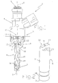
- 1 indicates as a whole a fuel injector, which has substantially cylindrical symmetry around a longitudinal axis 2 and can be controlled in order to inject liquid fuel, typically petrol or diesel, from its own injection nozzle 3.
- the injector 1 comprises an upper actuator body 4 which accommodates an electromagnetic actuator 5, and a lower valve body 6, which is integral with the actuator body 4 and accommodates a valve 7 which is actuated by the electromagnetic actuator 5 in order to regulate the flow of fuel from the injection nozzle 3.
- the actuator body 4 has a substantially cylindrical inner cavity 8, which receives the pressurised fuel from an upper supply aperture 9, ends in a lower aperture 10 which is engaged by the valve body 6, and accommodates the electromagnetic actuator 5.
- the electromagnetic actuator 5 comprises a fixed electromagnet 11, which can displace an anchor 12 made of ferromagnetic material along the axis 2 from a position of closure (not illustrated) to a position of opening (illustrated in figures 1 and 2) against the action of a spring 13 which tends to keep the anchor 12 in the position of closure.
- the valve body 6 comprises a substantially cylindrical tubular container 14 which accommodates a shutter or pin 15, which has an upper portion which is integral with the anchor 12 and co-operates with a valve seat 16 in order to regulate the flow of fuel from the injection nozzle 3 in a known manner.
- the tubular container 14 has a central cylindrical cavity 17, which extends along the entire length of the tubular container 14, is closed at the base in a fluid-tight manner by a sealing element 18 in which the valve seat 16 is defined and is partially closed at the top by a support element 19 which is disposed such as to define two supply apertures 20 which are disposed symmetrically on opposite side of the axis 2 and open into the cavity 17 for the supply of fuel to the cavity 17 itself.
- the support element 19 is defined by a bar, which is disposed symmetrically along a diameter of the circular upper end of the tubular container 14 and has a width which is smaller than the dimension of the cavity 17 such as to define the supply apertures 20 laterally; the support element 19 also has a through hole 21, which is disposed coaxially to the axis 2 and can accommodate the shutter 15 in a sliding manner such as to constitute an upper guide 22 for the shutter 15 itself.
- the support element 19 is initially in the form of a disc for closure of the upper end of the tubular container 14, the two supply apertures 20 being provided by means of subsequent removal (typically by means of milling) of respective lateral portions of this closure disc.
- valve body 6 has the advantage that it can be produced simply and economically, since it makes it possible to obtain simply and directly on the tubular container 14 both the upper guide 22 for the shutter 15, and the supply apertures 20.
- the tubular container 14 has at the top a pointed shape, which facilitates insertion of the valve seat 6 in the actuator body 4, and securing of the seat to the body; for this purpose, the tubular container 14 is made of hard stainless steel in order to press the flash which is present in the actuator body 4 at the moment of connection between the tubular container 14 and the actuator body 4, which is made of a soft type of magnetic stainless steel.
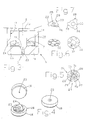
- the sealing element 18 is in the form of a disc and has an injection hole 23, which constitutes the injection nozzle 3 and in use is engaged by a pointed end portion of the shutter 15 in order to interrupt the flow of fuel which flows through the injection hole 23 itself; there is connected to the sealing element 18 a shaped body 24, which comprises a lower guide 25 for the shutter 15 and a rotary nozzle 26 which can impart rotational motion to the fuel which flows through the injection hole 23.
- the shaped body 24 is substantially the form of a disc which is perforated centrally, has an outer diameter which is smaller than the inner diameter of the tubular cavity 17, comprises a series of tangential channels 27 which are provided in its own lower portion, and comprises a number of outer radial projections 28 which have the function both of positioning the shaped body 24 inside the cavity 17, and the function of being connected to the sealing element 18 by being welded.
- Each tangential channel 27 extends between its own intake mouth 29 which is disposed in the vicinity of an outer periphery of the shaped body 24 and its own outlet 30 which opens into the central hole 31 in the shaped body 24; the intake mouths 29 are disposed laterally relative to the radial projections 28 such as to be independent from the radial projections 28 themselves, i.e. in other words, the projections 28 do not make any contribution towards defining the geometry of the intake mouths 29.
- This characteristic is particularly useful, since it makes it possible to determine the number, form and position of the projections 29 solely on the basis of the function of centring and securing of the shaped body 24, and permits simplification of the construction and fitting of the shaped body 24.
- the shaped body 24 is formed by the joining of two superimposed discs 32 and 33, the upper disc 33 is provided with the radial projections 28 and is provided with the lower guide 25 for the shutter 15, whereas the lower disc 32 is disposed between the sealing element 18 and the upper disc 33 and is provided with through grooves 34 which define the lateral walls of the tangential channels 27.
- the sealing element 18 defines the lower wall of the tangential channels 27 and the upper disc 33 defines the upper wall of the tangential channels 27 themselves.
- the three functions of fluid-tightness, generation of the tangential motion of the fuel injected, and guiding of the shutter 15, are allocated to three different components since the sealing element provides the fluid-tightness, the lower disc 32 generates the tangential motion, and the upper disc accommodates the lower guide 25 for the shutter 15; this structure has various advantages, since it permits considerable simplicity in production both of the sealing element 18, and of the discs 32 and 33, and permits a high level of flexibility in obtaining a wide range of calibrations of the rotary nozzle 26.
- the shaped body 24 is a monolithic body, in which there are defined both the lateral walls, and the upper wall of the tangential channels 27, whereas the lower wall of the tangential channels 27 is defined by an upper surface of the sealing element 18; this structure makes it possible to simplify the movement and fitting of the shaped body 24 on the sealing element 18.
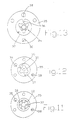
- the monolithic shaped body 24 (figure 13) or the two discs 32 and 33 which constitute the shaped body 24 (figures 11 and 12) are produced such that they are rendered integral with an appropriate service body 35 by means of a corresponding connection element 36.
- the corresponding service body 35 is disposed in a position which is determined in order to position the shaped body 24 in the required position relative to the sealing element 18; subsequently the position of the shaped body 24 is stabilised by connecting the shaped body 24 itself (typically by means of welding) to the sealing element 18, and the connection element 36 is interrupted by means of breakage in order to eliminate the service body 35.
- each service body 35 is in the shape of a disc and has a central hole 37, inside which there is disposed the shaped body 24 or the two discs 32 and 33 which constitute the shaped body 24; by means of this configuration the connection element 36 is disposed radially.
- each service body 35 has at least one positioning hole 38, which is connected in use to a corresponding stop device (which is known and not illustrated).
- each service body 35 has four positioning holes 38 in order to guarantee also correct orientation in relation to the sealing element 18 of the shaped body 24 or of the two discs 32 and 33 which constitute the shaped body 24.
- both the shaped body 24 and the two discs 32 and 33 which constitute the shaped body 24 are normally particularly complex to move and fit owing to their small dimensions (for example, the lower disc 32 typically has a diameter of 4 mm and a thickness of 0.2 mm).
Landscapes
- Engineering & Computer Science (AREA)
- Chemical & Material Sciences (AREA)
- Combustion & Propulsion (AREA)
- Mechanical Engineering (AREA)
- General Engineering & Computer Science (AREA)
- Physics & Mathematics (AREA)
- Electromagnetism (AREA)
- Fuel-Injection Apparatus (AREA)
Applications Claiming Priority (2)
| Application Number | Priority Date | Filing Date | Title |
|---|---|---|---|
| IT2001BO000482A ITBO20010482A1 (it) | 2001-07-27 | 2001-07-27 | Corpo valvola per un iniettore di carburante |
| ITBO20010482 | 2001-07-27 |
Publications (2)
| Publication Number | Publication Date |
|---|---|
| EP1279827A1 true EP1279827A1 (de) | 2003-01-29 |
| EP1279827B1 EP1279827B1 (de) | 2006-04-26 |
Family
ID=11439527
Family Applications (1)
| Application Number | Title | Priority Date | Filing Date |
|---|---|---|---|
| EP02016788A Expired - Lifetime EP1279827B1 (de) | 2001-07-27 | 2002-07-26 | Ventilkörper für ein Kraftstoffeinspritzventil |
Country Status (6)
| Country | Link |
|---|---|
| US (1) | US6817546B2 (de) |
| EP (1) | EP1279827B1 (de) |
| BR (1) | BR0203129B1 (de) |
| DE (1) | DE60210874T2 (de) |
| ES (1) | ES2260363T3 (de) |
| IT (1) | ITBO20010482A1 (de) |
Families Citing this family (3)
| Publication number | Priority date | Publication date | Assignee | Title |
|---|---|---|---|---|
| US7124966B2 (en) * | 2004-06-01 | 2006-10-24 | Haynes Corporation | Fuel injector check valve |
| WO2008065698A1 (fr) * | 2006-11-27 | 2008-06-05 | Mitsubishi Electric Corporation | Soupape d'injection de carburant |
| JP2012026466A (ja) * | 2010-07-20 | 2012-02-09 | Advics Co Ltd | 電磁弁 |
Citations (4)
| Publication number | Priority date | Publication date | Assignee | Title |
|---|---|---|---|---|
| US5192048A (en) * | 1992-06-26 | 1993-03-09 | Siemens Automotive L.P. | Fuel injector bearing cartridge |
| JPH08218980A (ja) * | 1995-02-13 | 1996-08-27 | Nippondenso Co Ltd | 燃料噴射装置 |
| US6182912B1 (en) * | 1997-08-22 | 2001-02-06 | Robert Bosch Gmbh | Fuel injection valve |
| US6202936B1 (en) * | 1999-12-28 | 2001-03-20 | Siemens Automotive Corporation | Fuel injector having a flat disk swirl generator |
Family Cites Families (5)
| Publication number | Priority date | Publication date | Assignee | Title |
|---|---|---|---|---|
| US4971254A (en) * | 1989-11-28 | 1990-11-20 | Siemens-Bendix Automotive Electronics L.P. | Thin orifice swirl injector nozzle |
| US5409169A (en) * | 1991-06-19 | 1995-04-25 | Hitachi America, Ltd. | Air-assist fuel injection system |
| US5875972A (en) * | 1997-02-06 | 1999-03-02 | Siemens Automotive Corporation | Swirl generator in a fuel injector |
| US6179227B1 (en) * | 1997-02-06 | 2001-01-30 | Siemens Automotive Corporation | Pressure swirl generator for a fuel injector |
| EP1049871B1 (de) * | 1998-08-27 | 2003-07-30 | Robert Bosch Gmbh | Brennstoffeinspritzventil |
-
2001
- 2001-07-27 IT IT2001BO000482A patent/ITBO20010482A1/it unknown
-
2002
- 2002-07-26 ES ES02016788T patent/ES2260363T3/es not_active Expired - Lifetime
- 2002-07-26 EP EP02016788A patent/EP1279827B1/de not_active Expired - Lifetime
- 2002-07-26 BR BRPI0203129-9A patent/BR0203129B1/pt not_active IP Right Cessation
- 2002-07-26 DE DE60210874T patent/DE60210874T2/de not_active Expired - Lifetime
- 2002-07-26 US US10/205,701 patent/US6817546B2/en not_active Expired - Fee Related
Patent Citations (4)
| Publication number | Priority date | Publication date | Assignee | Title |
|---|---|---|---|---|
| US5192048A (en) * | 1992-06-26 | 1993-03-09 | Siemens Automotive L.P. | Fuel injector bearing cartridge |
| JPH08218980A (ja) * | 1995-02-13 | 1996-08-27 | Nippondenso Co Ltd | 燃料噴射装置 |
| US6182912B1 (en) * | 1997-08-22 | 2001-02-06 | Robert Bosch Gmbh | Fuel injection valve |
| US6202936B1 (en) * | 1999-12-28 | 2001-03-20 | Siemens Automotive Corporation | Fuel injector having a flat disk swirl generator |
Non-Patent Citations (1)
| Title |
|---|
| PATENT ABSTRACTS OF JAPAN vol. 1996, no. 12 26 December 1996 (1996-12-26) * |
Also Published As
| Publication number | Publication date |
|---|---|
| BR0203129B1 (pt) | 2011-04-05 |
| ITBO20010482A0 (it) | 2001-07-27 |
| DE60210874T2 (de) | 2006-11-16 |
| BR0203129A (pt) | 2003-05-27 |
| US20030038187A1 (en) | 2003-02-27 |
| US6817546B2 (en) | 2004-11-16 |
| ES2260363T3 (es) | 2006-11-01 |
| ITBO20010482A1 (it) | 2003-01-27 |
| DE60210874D1 (de) | 2006-06-01 |
| EP1279827B1 (de) | 2006-04-26 |
Similar Documents
| Publication | Publication Date | Title |
|---|---|---|
| KR100254305B1 (ko) | 내연기관의 연료분사시스템용 연료분사밸브 | |
| JP3625831B2 (ja) | 燃料噴射装置のための流域の改善された可動子 | |
| JP3609831B2 (ja) | 複数の孔付きのディスク部材を有する燃料噴射装置 | |
| RU2177075C2 (ru) | Клапан с электромагнитным приводом | |
| KR100573185B1 (ko) | 전자기 작동 밸브 | |
| KR20000068730A (ko) | 연료 분사밸브 | |
| US6481646B1 (en) | Solenoid actuated fuel injector | |
| WO1992003653A1 (de) | Einspritzventil und verfahren zur herstellung eines einspritzventils | |
| KR100420746B1 (ko) | 전자식작동밸브,특히연료분사밸브 | |
| JP2008536049A (ja) | 燃料噴射弁 | |
| KR100420748B1 (ko) | 연료 분사 밸브 | |
| KR100378456B1 (ko) | 전자기작동식밸브 | |
| JP2007500822A (ja) | 双極磁気回路を有するモジュラー燃料噴射装置 | |
| JP2004505205A (ja) | 燃料噴射弁 | |
| US6817546B2 (en) | Valve body for a fuel injector | |
| JP2013007387A (ja) | 電磁的に操作される燃料噴射弁 | |
| GB2147949A (en) | Fuel injector for an I.C. engine | |
| KR20030007739A (ko) | 연료 분사 밸브 | |
| US6523759B1 (en) | Adjustable anti-bounce armature disk | |
| JP2004521266A (ja) | 内燃機関のための燃料噴射弁 | |
| JP2004513292A (ja) | 燃料噴射弁および該燃料噴射弁に用いられる弁ニードルまたは弁閉鎖体を製作するための方法 | |
| JP2002115625A (ja) | 燃料噴射弁 | |
| JP2011144731A (ja) | 燃料噴射弁 | |
| JP2007533558A (ja) | 弁、およびこうした弁を有する投与装置 | |
| JP2004509284A (ja) | 燃料噴射弁 |
Legal Events
| Date | Code | Title | Description |
|---|---|---|---|
| PUAI | Public reference made under article 153(3) epc to a published international application that has entered the european phase |
Free format text: ORIGINAL CODE: 0009012 |
|
| AK | Designated contracting states |
Designated state(s): AT BE BG CH CY CZ DE DK EE ES FI FR GB GR IE IT LI LU MC NL PT SE SK TR |
|
| AX | Request for extension of the european patent |
Extension state: AL LT LV MK RO SI |
|
| 17P | Request for examination filed |
Effective date: 20030714 |
|
| AKX | Designation fees paid |
Designated state(s): DE ES FR GB SE |
|
| 17Q | First examination report despatched |
Effective date: 20040129 |
|
| GRAP | Despatch of communication of intention to grant a patent |
Free format text: ORIGINAL CODE: EPIDOSNIGR1 |
|
| GRAS | Grant fee paid |
Free format text: ORIGINAL CODE: EPIDOSNIGR3 |
|
| GRAA | (expected) grant |
Free format text: ORIGINAL CODE: 0009210 |
|
| RAP1 | Party data changed (applicant data changed or rights of an application transferred) |
Owner name: MAGNETI MARELLI POWERTRAIN S.P.A. |
|
| AK | Designated contracting states |
Kind code of ref document: B1 Designated state(s): DE ES FR GB SE |
|
| REG | Reference to a national code |
Ref country code: GB Ref legal event code: FG4D |
|
| REF | Corresponds to: |
Ref document number: 60210874 Country of ref document: DE Date of ref document: 20060601 Kind code of ref document: P |
|
| REG | Reference to a national code |
Ref country code: SE Ref legal event code: TRGR |
|
| ET | Fr: translation filed | ||
| REG | Reference to a national code |
Ref country code: ES Ref legal event code: FG2A Ref document number: 2260363 Country of ref document: ES Kind code of ref document: T3 |
|
| PLBE | No opposition filed within time limit |
Free format text: ORIGINAL CODE: 0009261 |
|
| STAA | Information on the status of an ep patent application or granted ep patent |
Free format text: STATUS: NO OPPOSITION FILED WITHIN TIME LIMIT |
|
| 26N | No opposition filed |
Effective date: 20070129 |
|
| PGFP | Annual fee paid to national office [announced via postgrant information from national office to epo] |
Ref country code: ES Payment date: 20090727 Year of fee payment: 8 |
|
| PGFP | Annual fee paid to national office [announced via postgrant information from national office to epo] |
Ref country code: GB Payment date: 20090728 Year of fee payment: 8 Ref country code: SE Payment date: 20090727 Year of fee payment: 8 |
|
| GBPC | Gb: european patent ceased through non-payment of renewal fee |
Effective date: 20100726 |
|
| PG25 | Lapsed in a contracting state [announced via postgrant information from national office to epo] |
Ref country code: GB Free format text: LAPSE BECAUSE OF NON-PAYMENT OF DUE FEES Effective date: 20100726 |
|
| REG | Reference to a national code |
Ref country code: ES Ref legal event code: FD2A Effective date: 20110818 |
|
| PG25 | Lapsed in a contracting state [announced via postgrant information from national office to epo] |
Ref country code: ES Free format text: LAPSE BECAUSE OF NON-PAYMENT OF DUE FEES Effective date: 20100727 |
|
| PGFP | Annual fee paid to national office [announced via postgrant information from national office to epo] |
Ref country code: DE Payment date: 20110708 Year of fee payment: 10 Ref country code: FR Payment date: 20110810 Year of fee payment: 10 |
|
| PG25 | Lapsed in a contracting state [announced via postgrant information from national office to epo] |
Ref country code: SE Free format text: LAPSE BECAUSE OF NON-PAYMENT OF DUE FEES Effective date: 20100727 |
|
| REG | Reference to a national code |
Ref country code: FR Ref legal event code: ST Effective date: 20130329 |
|
| PG25 | Lapsed in a contracting state [announced via postgrant information from national office to epo] |
Ref country code: DE Free format text: LAPSE BECAUSE OF NON-PAYMENT OF DUE FEES Effective date: 20130201 Ref country code: FR Free format text: LAPSE BECAUSE OF NON-PAYMENT OF DUE FEES Effective date: 20120731 |
|
| REG | Reference to a national code |
Ref country code: DE Ref legal event code: R119 Ref document number: 60210874 Country of ref document: DE Effective date: 20130201 |