EP1279804A1 - Luftansaugkanalsystem für Brennkraftmaschinen - Google Patents
Luftansaugkanalsystem für Brennkraftmaschinen Download PDFInfo
- Publication number
- EP1279804A1 EP1279804A1 EP02014757A EP02014757A EP1279804A1 EP 1279804 A1 EP1279804 A1 EP 1279804A1 EP 02014757 A EP02014757 A EP 02014757A EP 02014757 A EP02014757 A EP 02014757A EP 1279804 A1 EP1279804 A1 EP 1279804A1
- Authority
- EP
- European Patent Office
- Prior art keywords
- air intake
- bearing
- duct system
- intake duct
- channel
- Prior art date
- Legal status (The legal status is an assumption and is not a legal conclusion. Google has not performed a legal analysis and makes no representation as to the accuracy of the status listed.)
- Granted
Links
- 238000002485 combustion reaction Methods 0.000 title claims description 4
- 238000005538 encapsulation Methods 0.000 claims description 2
- 229910000760 Hardened steel Inorganic materials 0.000 description 1
- 229910000831 Steel Inorganic materials 0.000 description 1
- 230000037431 insertion Effects 0.000 description 1
- 238000003780 insertion Methods 0.000 description 1
- 238000009434 installation Methods 0.000 description 1
- 239000000463 material Substances 0.000 description 1
- 239000002184 metal Substances 0.000 description 1
- 238000000465 moulding Methods 0.000 description 1
- 239000010959 steel Substances 0.000 description 1
Images

Classifications
-
- F—MECHANICAL ENGINEERING; LIGHTING; HEATING; WEAPONS; BLASTING
- F02—COMBUSTION ENGINES; HOT-GAS OR COMBUSTION-PRODUCT ENGINE PLANTS
- F02B—INTERNAL-COMBUSTION PISTON ENGINES; COMBUSTION ENGINES IN GENERAL
- F02B27/00—Use of kinetic or wave energy of charge in induction systems, or of combustion residues in exhaust systems, for improving quantity of charge or for increasing removal of combustion residues
- F02B27/02—Use of kinetic or wave energy of charge in induction systems, or of combustion residues in exhaust systems, for improving quantity of charge or for increasing removal of combustion residues the systems having variable, i.e. adjustable, cross-sectional areas, chambers of variable volume, or like variable means
- F02B27/0226—Use of kinetic or wave energy of charge in induction systems, or of combustion residues in exhaust systems, for improving quantity of charge or for increasing removal of combustion residues the systems having variable, i.e. adjustable, cross-sectional areas, chambers of variable volume, or like variable means characterised by the means generating the charging effect
- F02B27/0247—Plenum chambers; Resonance chambers or resonance pipes
- F02B27/0257—Rotatable plenum chambers
-
- F—MECHANICAL ENGINEERING; LIGHTING; HEATING; WEAPONS; BLASTING
- F02—COMBUSTION ENGINES; HOT-GAS OR COMBUSTION-PRODUCT ENGINE PLANTS
- F02B—INTERNAL-COMBUSTION PISTON ENGINES; COMBUSTION ENGINES IN GENERAL
- F02B27/00—Use of kinetic or wave energy of charge in induction systems, or of combustion residues in exhaust systems, for improving quantity of charge or for increasing removal of combustion residues
- F02B27/02—Use of kinetic or wave energy of charge in induction systems, or of combustion residues in exhaust systems, for improving quantity of charge or for increasing removal of combustion residues the systems having variable, i.e. adjustable, cross-sectional areas, chambers of variable volume, or like variable means
- F02B27/0205—Use of kinetic or wave energy of charge in induction systems, or of combustion residues in exhaust systems, for improving quantity of charge or for increasing removal of combustion residues the systems having variable, i.e. adjustable, cross-sectional areas, chambers of variable volume, or like variable means characterised by the charging effect
- F02B27/0215—Oscillating pipe charging, i.e. variable intake pipe length charging
-
- Y—GENERAL TAGGING OF NEW TECHNOLOGICAL DEVELOPMENTS; GENERAL TAGGING OF CROSS-SECTIONAL TECHNOLOGIES SPANNING OVER SEVERAL SECTIONS OF THE IPC; TECHNICAL SUBJECTS COVERED BY FORMER USPC CROSS-REFERENCE ART COLLECTIONS [XRACs] AND DIGESTS
- Y02—TECHNOLOGIES OR APPLICATIONS FOR MITIGATION OR ADAPTATION AGAINST CLIMATE CHANGE
- Y02T—CLIMATE CHANGE MITIGATION TECHNOLOGIES RELATED TO TRANSPORTATION
- Y02T10/00—Road transport of goods or passengers
- Y02T10/10—Internal combustion engine [ICE] based vehicles
- Y02T10/12—Improving ICE efficiencies
Definitions
- the invention relates to an air intake duct system for internal combustion engines, in particular for V-engines.
- each helical air intake passage has an inlet port connected to a central inner portion of the air intake system, through which air enters the helical passage and, after flowing through the helical passage, is directed to the corresponding cylinder.
- a tubular duct part through which the inner wall of the spiral duct is formed and which has the air inlet opening.
- the tubular channel part is pivotally arranged so that the position of the air inlet opening can be varied.
- the individual, the intake ducts forming channel parts are adjacent to each other or stacked arranged, wherein the air intake ducts formed are alternately connected to one or the other row of the cylinder of the V-engine.
- the inner pivoting channel parts are these connected to a pivot axis.
- Each connected to one side of the V-engine air intake ducts have the same length and are thus actuated together via a pivot axis.
- the air intake duct system thus has two pivot axes which are each connected to the pivotable channel parts for one or the other row of cylinders of the V-engine.
- the individual air intake ducts of one or the other row of cylinders are arranged alternately in the air intake duct system.
- the two pivot axes are thus only connected to each second pivotable channel part of the air intake system and only passed through the other channel part.
- the bearing of the pivot axes for example, in individual plain bearing sleeves.
- the existing example of hardened steel plain bearing sleeves are arranged in a housing of the air intake duct system or in the fixed channel parts.
- the provision of individual bearing sleeves for the two pivot axes has the disadvantage that due to a minimum thickness of the bearing sleeves and the resulting minimum distance of the pivot axes of the required space is relatively large.
- Another possibility is to store the usually made of metal pivot axes directly in the channel parts made of plastic. In this case, however, occurs a relatively high wear, so that the required average life can not be reliably achieved.
- the object of the invention is to reduce the required space for Luftansaugkanalsysteme.
- a reduction of the required installation space of the air intake duct system can be achieved according to the invention by arranging the two pivot axes at a small distance from each other. Since storage in plastic due to the wear occurring is disadvantageous, a common, one-piece bearing part is provided according to the invention, which comprises two pivot axis bearing for each one of the two pivot axes. Preferably, there are two plain bearing sleeves that overlap each other, so that the bearing part has the shape of an 8. An arranged between the two bearing sleeves intermediate wall serves as a sleeve wall for both bearing sleeves. In contrast to two juxtaposed identical bearing sleeves, the two cylindrical sleeves in the openings of the bearing part according to the invention can be arranged considerably closer to each other, so that the required space is reduced.
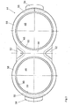
- the air intake duct system has eight spiral-shaped air intake ducts 10, 12.
- the intake ports 10 are connected via lugs 14 to one side of the V-engine and the intake ports 12 via lugs 16 to the other side of the V-engine.
- the individual intake passages are each formed by a first, in the illustrated embodiment, fixed channel part 18 and a second, pivotable channel part 20,22.
- first Channel parts 18 constructed identically and, as shown in Fig. 1, arranged side by side or stacked.
- the first channel parts 18 are arranged in a housing 24 consisting of two housing halves.
- the pivotable second channel parts 20 and 22 are also identical.
- the air to be supplied to the individual intake ducts 10, 12 is conducted via an intake manifold 26 in the direction of an arrow 28 into the inner region of the air intake system.
- the inner region is formed by the juxtaposed pivotable channel parts 20,22, which are each substantially circular cylindrical.
- additional intake openings may possibly be connected to the individual air intake ducts 10, 12, so that air enters the air intake ducts 10, 12 both through the central region of the air intake duct system and through the additional supply ducts. From the central region of the air intake duct system, the air passes through air inlet openings provided in the pivotable duct parts 20, 22 into the corresponding air intake ducts 10, 12. From these, the air exits through air outlet openings 30 and 32 and is guided by channels, not shown, to the corresponding cylinders.
- the pivotable duct parts 20, 22 are fixedly connected to pivot axes 34, 36.
- the air inlet openings of the pivotable channel parts 20,22 are changed in their position, so that the air from the central region at another point in the spiral air intake ducts 10,12 occurs and thus a shorter or longer way.
- the second channel parts 20 are connected via webs with brackets 40 and form an adjusting element.
- the brackets 40 are connected to the pivot axis 36 via a tubular profile (square).
- the connection between the brackets 40 and the pivot axis 36 is additionally via leaf springs.
- the Brackets 40 are connected via webs to the second channel part 20.
- the channel parts 22 via webs and brackets 42 are connected to the pivot axis 34.
- the channel parts 20 and 22 are thus always pivoted together, so that the air intake ducts 10 and 12 on each side of the V-engine are the same length.
- the bearing parts 44 are each arranged in radial walls 46 of the fixed first channel parts 18.
- the number of bearings can vary depending on the required accuracy and the material used.
- the bearing parts 44 are made of sintered steel, GGG or are designed as a forged part.
- the bearing parts 44 are preferably held by molding in the walls 46 of the channel parts 18.
- the bearing part 44 (FIG. 2) has two cylindrical openings 46, so that the inner walls 48 form two cylindrical bearing sleeves for accommodating the two pivot axes 34, 36. In order to facilitate the insertion of the pivot axes 34,36 in the openings 46, these have a chamfer 50 on.
- a web 52 is provided in each of the constriction.
- two lugs 54 which do not extend over the entire height of the bearing part 44, are provided on the outer walls of the sleeves. Both the webs 52 and the lugs 54 are encapsulated by the encapsulation of the bearing part 44 of plastic. Instead of or in addition to the lugs 54 also undercuts or slots 55 may be provided. As a result, the bearing members 44 are held firmly in the walls 46 of the fixed channel parts 18.
- the provision of a common bearing part 44 according to the invention for the two pivot axes also has the advantage that the distance between the two pivot axes is clearly defined.
- the substantially in the form of an 8 bearing member 44 has a common sleeve wall 56.
- the common sleeve wall 56 is disposed between the two bearing sleeves 48 and serves as a wall for both bearing sleeves 48.
- the strength of the common sleeve wall 56 can be made thinner than the thickness of the individual or outer sleeve walls 58. According to the invention, the strength of the common Sleeve wall 56 less than 1.5 times the individual sleeve walls 58. Particularly preferred is a strength of the common sleeve wall 56, which corresponds approximately to the thickness of the individual sleeve wall 58. In this way, the distance between the two mounted in the bearing sleeves 48 pivot axes 34,36 can be minimized.
Landscapes
- Engineering & Computer Science (AREA)
- Chemical & Material Sciences (AREA)
- Combustion & Propulsion (AREA)
- Mechanical Engineering (AREA)
- General Engineering & Computer Science (AREA)
- Characterised By The Charging Evacuation (AREA)
Abstract
Description
- Die Erfindung betrifft ein Luftansaugkanalsystem für Brennkraftmaschinen, insbesondere für V-Motoren.
- Aus DE 197 56 332 ist ein Luftansaugkanalsystem bekannt, bei dem die Länge mehrerer jeweils mit einem Zylinder einer Brennkraftmaschine verbindbarer Luftansaugkanäle stufenlos variiert werden kann. Hierzu sind die spiralförmig ausgebildeten Ansaugkanäle nebeneinander angeordnet. Jeder spiralförmige Luftansaugkanal weist eine mit einem zentralen Innenbereich des Luftansaugsystems verbundene Einlaßöffnung auf, durch die Luft in den spiralförmigen Kanal eintritt und nach Durchströmen des spiralförmigen Kanals zu dem entsprechenden Zylinder geleitet wird. Innerhalb des zentralen Bereichs ist ein rohrförmiges Kanalteil angeordnet, durch das die Innenwand des spiralförmigen Kanals gebildet ist und der die Lufteinlaßöffnung aufweist. Der rohrförmige Kanalteil ist schwenkbar angeordnet, so dass die Lage der Lufteintrittsöffnung variiert werden kann. Durch Schwenken des rohrförmigen Kanalteils kann somit die Länge des Luftansaugkanals, d.h. die von der Luft zu durchströmende Strecke zwischen Lufteintrittsöffnung und Luftaustrittsöffnung, stufenlos variiert werden.
- Die einzelnen, die Ansaugkanäle bildenden Kanalteile sind benachbart zueinander bzw. stapelförmig angeordnet, wobei die ausgebildeten Luftansaugkanäle abwechselnd mit der einen oder anderen Reihe der Zylinder des V-Motors verbunden sind. Zum Schwenken der inneren schwenkbaren Kanalteile sind diese mit einer Schwenkachse verbunden. Die jeweils mit einer Seite des V-Motors verbundenen Luftansaugkanäle weisen die gleiche Länge auf und werden somit gemeinsam über eine Schwenkachse betätigt. Das Luftansaugkanalsystem weist somit zwei Schwenkachsen auf, die jeweils mit den schwenkbaren Kanalteilen für die eine bzw. die andere Zylinderreihe des V-Motors verbunden sind. Um möglichst gleich lange Luftansaugkanäle zu den einzelnen Zylindern realisieren zu können, sind in dem Luftansaugkanalsystem die einzelnen Luftansaugkanäle der einen bzw. der anderen Zylinderreihe abwechselnd angeordnet. Die beiden Schwenkachsen sind somit nur mit jedem zweiten schwenkbaren Kanalteil des Luftansaugsystems verbunden und durch das jeweils andere Kanalteil nur hindurchgeführt.
- Die Lagerung der Schwenkachsen erfolgt beispielsweise in einzelnen Gleitlagerhülsen. Die beispielsweise aus gehärtetem Stahl bestehenden Gleitlagerhülsen sind in einem Gehäuse des Luftansaugkanalsystems oder in den feststehenden Kanalteilen angeordnet. Das Vorsehen einzelner Lagerhülsen für die beiden Schwenkachsen weist den Nachteil auf, dass auf Grund einer Mindestdicke der Lagerhülsen und des sich hieraus ergebenden Mindestabstands der Schwenkachsen der erforderliche Bauraum relativ groß ist.
- Eine weitere Möglichkeit besteht darin, die üblicherweise aus Metall bestehenden Schwenkachsen direkt in den Kanalteilen aus Kunststoff zu lagern. Hierbei tritt jedoch ein relativ hoher Verschleiß auf, so dass die geforderte durchschnittliche Lebensdauer nicht zuverlässig erreicht werden kann.
- Aufgabe der Erfindung ist es, den erforderlichen Bauraum für Luftansaugkanalsysteme zu verringern.
- Die Lösung der Aufgabe erfolgt erfindungsgemäß durch die Merkmale des Patentanspruchs 1.
- Eine Verringerung des erforderlichen Bauraums des Luftansaugkanalsystems kann erfindungsgemäß durch Anordnen der beiden Schwenkachsen in geringem Abstand zueinander erzielt werden. Da eine Lagerung in Kunststoff auf Grund des auftretenden Verschleißes nachteilig ist, ist erfindungsgemäß ein gemeinsames, einstückiges Lagerteil vorgesehen, das zwei Schwenkachsenlager für je eine der beiden Schwenkachsen umfasst. Vorzugsweise handelt es sich um zwei Gleitlagerhülsen, die einander überschneiden, so dass das Lagerteil die Form einer 8 aufweist. Eine zwischen den beiden Lagerhülsen angeordnete Zwischenwand dient als Hülsenwand für beide Lagerhülsen. Im Unterschied zu zwei nebeneinander angeordneten identischen Lagerhülsen können die beiden zylindrischen Hülsen in den Öffnungen des erfindungsgemäßen Lagerteils erheblich näher nebeneinander angeordnet werden, so dass der erforderliche Bauraum verringert ist.
- Nachfolgend wird die Erfindung anhand einer bevorzugten Ausführungsform unter Bezugnahme auf die anliegenden Zeichnungen näher erläutert.
- Es zeigen:
- Fig. 1
- eine schematische Schnittansicht eines Luftansaugkanalsystems für einen 8-Zylinder-V-Motor und
- Fig. 2
- eine schematische Draufsicht des erfindungsgemäßen Lagerteils.
- Das Luftansaugkanalsystem weist acht spiralförmig verlaufende Luftansaugkanäle 10,12 auf. Hierbei sind die Ansaugkanäle 10 über Ansätze 14 mit der einen Seite des V-Motors und die Ansaugkanäle 12 über Ansätze 16 mit der anderen Seite des V-Motors verbunden. Die einzelnen Ansaugkanäle sind jeweils durch ein erstes, im dargestellten Ausführungsbeispiel feststehendes Kanalteil 18 und ein zweites, schwenkbares Kanalteil 20,22 gebildet. Mit Ausnahme der beiden in der Figur am linken und rechten Rand vorgesehenen Kanalteile sind sämtliche erste Kanalteile 18 identisch aufgebaut und, wie in Fig. 1 dargestellt, nebeneinander angeordnet bzw. aufeinander gestapelt. Die ersten Kanalteile 18 sind in einem aus zwei Gehäusehälften bestehenden Gehäuse 24 angeordnet. Die schwenkbaren zweiten Kanalteile 20 und 22 sind ebenfalls identisch.
- Die den einzelnen Ansaugkanälen 10,12 zuzuführende Luft wird über einen Ansaugstutzen 26 in Richtung eines Pfeils 28 in den inneren Bereich des Luftansaugsystems geleitet. Der innere Bereich ist durch die nebeneinander angeordneten schwenkbaren Kanalteile 20,22, die jeweils im wesentlichen kreiszylinderförmig sind, gebildet. Je nach Ausführungsform sind ggf. zusätzliche Ansaugöffnungen mit den einzelnen Luftansaugkanälen 10,12 verbunden, so dass sowohl durch den zentralen Bereich des Luftansaugkanalsystems als auch durch die zusätzlichen Zuführkanäle Luft in die Luftansaugkanäle 10,12 gelangt. Aus dem zentralen Bereich des Luftansaugkanalsystems gelangt die Luft durch in den schwenkbaren Kanalteilen 20,22 vorgesehene Lufteinlaßöffnungen in die entsprechenden Luftansaugkanäle 10,12. Aus diesen tritt die Luft durch Luftauslaßöffnungen 30 bzw. 32 aus und wird durch nicht dargestellte Kanäle zu den entsprechenden Zylindern geführt.
- Zum Variieren der Länge der Luftansaugkanäle 10,12 sind die schwenkbaren Kanalteile 20,22 mit Schwenkachsen 34,36 fest verbunden. Durch Schwenken der Schwenkachsen 34,36 mit Hilfe eines Stellelements 38 werden die Lufteinlaßöffnungen der schwenkbaren Kanalteile 20,22 in ihrer Lage verändert, so dass die Luft aus dem zentralen Bereich an einer anderen Stelle in die spiralförmigen Luftansaugkanäle 10,12 eintritt und somit einen kürzeren oder längeren Weg zurücklegen muß.
- Die zweiten Kanalteile 20 sind über Stege mit Halterungen 40 verbunden und bilden ein Verstellelement. Die Halterungen 40 sind mit der Schwenkachse 36 über ein Rohrprofil (Vierkant) verbunden. Die Verbindung zwischen den Halterungen 40 und der Schwenkachse 36 erfolgt zusätzlich über Blattfedern. Die Halterungen 40 sind über Stege mit dem zweiten Kanalteil 20 verbunden. Entsprechend sind die Kanalteile 22 über Stege und Halterungen 42 mit der Schwenkachse 34 verbunden. Die Kanalteile 20 bzw. 22 werden somit stets gemeinsam verschwenkt, so dass die Luftansaugkanäle 10 bzw. 12 je Seite des V-Motors gleich lang sind.
- Die Lagerung der beiden Schwenkachsen 34,36 erfolgt erfindungsgemäß durch ein Lagerteil 44, in dem die beiden Achsen gemeinsam gelagert sind. Die Lagerteile 44 sind jeweils in radialen Wänden 46 der feststehenden ersten Kanalteile 18 angeordnet. Die Anzahl der Lager kann hierbei je nach geforderter Genauigkeit und verwendetem Werkstoff variieren. Die Lagerteile 44 bestehen aus gesintertem Stahl, GGG oder sind als Schmiedeteil ausgebildet. Die Lagerteile 44 sind vorzugsweise durch Umspritzen in den Wänden 46 der Kanalteile 18 gehalten.
- Das Lagerteil 44 (Fig. 2) weist zwei zylindrische Öffnungen 46 auf, so dass die Innenwände 48 zwei zylindrische Lagerhülsen zur Aufnahme der beiden Schwenkachsen 34,36 bilden. Um das Einführen der Schwenkachsen 34,36 in die Öffnungen 46 zu erleichtern, weisen diese eine Fase 50 auf. Zur Versteifung der beiden zu einer 8 verbundenen Hülsen ist in den Einschnürungsbereichen jeweils ein Steg 52 vorgesehen. Ferner sind an den Außenwänden der Hülsen zwei Ansätze 54, die sich nicht über die gesamte Höhe des Lagerteils 44 erstrecken, vorgesehen. Sowohl die Stege 52 als auch die Ansätze 54 werden beim Umspritzen des Lagerteils 44 von Kunststoff umspritzt. Anstatt oder zusätzlich zu den Ansätzen 54 können auch Hinterschneidungen bzw. Schlitze 55 vorgesehen sein. Hierdurch sind die Lagerteile 44 fest in den Wänden 46 der feststehenden Kanalteile 18 gehalten. Das Vorsehen eines gemeinsamen erfindungsgemäßen Lagerteils 44 für die beiden Schwenkachsen weist ferner den Vorteil auf, dass der Abstand der beiden Schwenkachsen eindeutig definiert ist.
- Das im Wesentlichen die Form einer 8 aufweisende Lagerteil 44 weist eine gemeinsame Hülsenwand 56 auf. Die gemeinsame Hülsenwand 56 ist zwischen den beiden Lagerhülsen 48 angeordnet und dient als Wand für beide Lagerhülsen 48. Die Stärke der gemeinsamen Hülsenwand 56 kann erfindungsgemäß dünner ausgebildet werden als die doppelte Stärke der einzelnen bzw. außen liegenden Hülsenwände 58. Vorzugsweise beträgt die Stärke der gemeinsamen Hülsenwand 56 weniger als das 1,5-fache der einzelnen Hülsenwände 58. Besonders bevorzugt ist eine Stärke der gemeinsamen Hülsenwand 56, die etwa der Stärke der einzelnen Hülsenwand 58 entspricht. Hierdurch kann der Abstand der beiden in den Lagerhülsen 48 gelagerten Schwenkachsen 34,36 minimiert werden.
Claims (7)
- Luftansaugkanalsystem für Brennkraftmaschinen, mit
mehreren jeweils mindestens durch ein erstes und ein zweites Kanalteil (18;20,22) ausgebildeten Luftansaugkanälen (10,12),
einer in einem der Kanalteile (20,22) vorgesehenen Lufteinlaßöffnung und einer im anderen Kanalteil (18) vorgesehenen Luftauslaßöffnung (30,32), wobei zumindest eines der Kanalteile (20,22) zum Variieren der Länge des jeweiligen Luftansaugkanals (10,12) schwenkbar ist,
zwei Schwenkachsen (34,36), die jeweils mit mindestens einem schwenkbaren Kanalteil (20,22) verbunden sind, und
Schwenkachsenlagern (48) zur Aufnahme der Schwenkachsen (34,36),
gekennzeichnet durch
ein einstückiges, zwei Schwenkachsenlager (48) für je eine der beiden Schwenkachsen (34,36) umfassendes Lagerteil (44). - Luftansaugkanalsystem nach Anspruch 1, dadurch gekennzeichnet, dass die Schwenklager durch zwei Lagerhülsen (48) gebildet sind.
- Luftansaugkanalsystem nach Anspruch 2, dadurch gekennzeichnet, dass das Lagerteil (44) zwischen den beiden Lagerhülsen (48) eine gemeinsame Hülsenwand (56) aufweist.
- Luftansaugkanalsystem nach Anspruch 3, dadurch gekennzeichnet, dass die gemeinsame Hülsenwand (56) im Wesentlichen die gleiche Stärke wie die einzelnen Hülsenwände (58) aufweist.
- Luftansaugkanalsystem nach einem der Ansprüche 1-4, dadurch gekennzeichnet, dass das Lagerteil (44) im Querschnitt 8-förmig ist.
- Luftansaugkanalsystem nach einem der Ansprüche 1-5, dadurch gekennzeichnet, dass das Lagerteil (44) in dem feststehenden Kanalteil (18) angeordnet ist.
- Luftansaugkanalsystem nach einem der Ansprüche 1-6, dadurch gekennzeichnet, dass das Lagerteil (44) durch zumindest teilweises Umspritzen mit Kunststoff mit dem feststehenden Kanalteil (18) verbunden ist.
Applications Claiming Priority (2)
| Application Number | Priority Date | Filing Date | Title |
|---|---|---|---|
| DE10137077A DE10137077C2 (de) | 2001-07-28 | 2001-07-28 | Luftansaugkanalsystem für Brennkraftmaschinen |
| DE10137077 | 2001-07-28 |
Publications (2)
| Publication Number | Publication Date |
|---|---|
| EP1279804A1 true EP1279804A1 (de) | 2003-01-29 |
| EP1279804B1 EP1279804B1 (de) | 2005-03-23 |
Family
ID=7693585
Family Applications (1)
| Application Number | Title | Priority Date | Filing Date |
|---|---|---|---|
| EP02014757A Expired - Lifetime EP1279804B1 (de) | 2001-07-28 | 2002-07-04 | Luftansaugkanalsystem für Brennkraftmaschinen |
Country Status (4)
| Country | Link |
|---|---|
| US (1) | US6732696B2 (de) |
| EP (1) | EP1279804B1 (de) |
| DE (2) | DE10137077C2 (de) |
| ES (1) | ES2236401T3 (de) |
Families Citing this family (3)
| Publication number | Priority date | Publication date | Assignee | Title |
|---|---|---|---|---|
| DE10347574B3 (de) * | 2003-10-14 | 2004-12-16 | Pierburg Gmbh | Luftansaugkanalsystem |
| US7275511B1 (en) * | 2006-07-26 | 2007-10-02 | Gm Global Technology Operations, Inc. | Intake manifold assembly |
| ES2292358B1 (es) * | 2006-08-31 | 2009-02-01 | Lekue, S.L. | Recipiente para la coccion de alimentos al vapor. |
Citations (3)
| Publication number | Priority date | Publication date | Assignee | Title |
|---|---|---|---|---|
| EP0848145A2 (de) * | 1996-12-11 | 1998-06-17 | Bayerische Motoren Werke Aktiengesellschaft, Patentabteilung AJ-3 | Sauganlage für eine Brennkraftmaschine der V-Bauart |
| DE19756332A1 (de) * | 1997-12-18 | 1999-06-24 | Pierburg Ag | Luftansaugkanalsystem für eine Brennkraftmaschine |
| DE10016027A1 (de) * | 2000-03-31 | 2001-10-04 | Montaplast Gmbh | Variable Luftansaugvorrichtung |
-
2001
- 2001-07-28 DE DE10137077A patent/DE10137077C2/de not_active Expired - Fee Related
-
2002
- 2002-07-04 EP EP02014757A patent/EP1279804B1/de not_active Expired - Lifetime
- 2002-07-04 ES ES02014757T patent/ES2236401T3/es not_active Expired - Lifetime
- 2002-07-04 DE DE50202523T patent/DE50202523D1/de not_active Expired - Lifetime
- 2002-07-12 US US10/194,830 patent/US6732696B2/en not_active Expired - Fee Related
Patent Citations (3)
| Publication number | Priority date | Publication date | Assignee | Title |
|---|---|---|---|---|
| EP0848145A2 (de) * | 1996-12-11 | 1998-06-17 | Bayerische Motoren Werke Aktiengesellschaft, Patentabteilung AJ-3 | Sauganlage für eine Brennkraftmaschine der V-Bauart |
| DE19756332A1 (de) * | 1997-12-18 | 1999-06-24 | Pierburg Ag | Luftansaugkanalsystem für eine Brennkraftmaschine |
| DE10016027A1 (de) * | 2000-03-31 | 2001-10-04 | Montaplast Gmbh | Variable Luftansaugvorrichtung |
Also Published As
| Publication number | Publication date |
|---|---|
| US20030019458A1 (en) | 2003-01-30 |
| DE10137077C2 (de) | 2003-05-28 |
| DE50202523D1 (de) | 2005-04-28 |
| EP1279804B1 (de) | 2005-03-23 |
| US6732696B2 (en) | 2004-05-11 |
| DE10137077A1 (de) | 2003-02-20 |
| ES2236401T3 (es) | 2005-07-16 |
Similar Documents
| Publication | Publication Date | Title |
|---|---|---|
| DE4133033C2 (de) | Schwinghebel | |
| DE68912457T2 (de) | Kühlsystem für eine Brennkraftmaschine mit mehreren Zylindern. | |
| DE102004015926B4 (de) | Einlassverteiler aus Harz | |
| DE3321846C2 (de) | ||
| DE19818589A1 (de) | Brennkraftmaschine | |
| EP1510681A1 (de) | Zylinderkopfdichtung | |
| EP0480393B1 (de) | Brennkraftmaschine mit einem zylindrischen Schieber | |
| EP1657512B1 (de) | Wärmetauscher mit offenem Profil als Gehäuse | |
| DE102008035957A1 (de) | Zylinderkopf für eine Brennkraftmaschine | |
| EP2032330B1 (de) | Formnestkavität mit entkoppelter Kühlkanalführung | |
| EP0819837B1 (de) | Kühlkreislauf einer Brennkraftmaschine | |
| EP0486463B1 (de) | Gussform für den Zylinderblock einer Brennkraftmaschine mit zwei in V-Form angeordneten Zylinderreihen | |
| AT410242B (de) | Mehrzylinder-brennkraftmaschine mit zwei einlass- und zwei auslassventilen | |
| DE10137077C2 (de) | Luftansaugkanalsystem für Brennkraftmaschinen | |
| DE19641811A1 (de) | Ventilanordnung für Verbrennungsmotoren | |
| DE102009008237B4 (de) | Brennkraftmaschine mit getrennten Kühlmittelräumen im Zylinderkopf | |
| DE10143384C1 (de) | Schaltklappeneinrichtung | |
| DE10236393A1 (de) | Ansaugkanalsystem | |
| EP1283335B1 (de) | Luftansaugkanalsystem für Brennkraftmaschinen | |
| EP0753657A1 (de) | Ansaugluftleitung für einen Verbrennungsmotor | |
| DE60007503T2 (de) | Ventilsteuerungseinrichtung für eine Brennkraftmaschine | |
| DE19857607B4 (de) | Brennkraftmaschine mit zwei V-förmig angeordneten Zylinderbänken | |
| EP3268597B1 (de) | Brennkraftmaschine mit zumindest einem zylinder | |
| DE3136374A1 (de) | Verdampfer, insbesondere fuer klimaanlagen in kraftfahrzeugen | |
| DE10215604A1 (de) | Luftansaugkanalsystem für Brennkraftmaschinen |
Legal Events
| Date | Code | Title | Description |
|---|---|---|---|
| PUAI | Public reference made under article 153(3) epc to a published international application that has entered the european phase |
Free format text: ORIGINAL CODE: 0009012 |
|
| AK | Designated contracting states |
Designated state(s): AT BE BG CH CY CZ DE DK EE ES FI FR GB GR IE IT LI LU MC NL PT SE SK TR |
|
| AX | Request for extension of the european patent |
Extension state: AL LT LV MK RO SI |
|
| 17P | Request for examination filed |
Effective date: 20030722 |
|
| AKX | Designation fees paid |
Designated state(s): DE ES FR GB IT |
|
| 17Q | First examination report despatched |
Effective date: 20031107 |
|
| GRAP | Despatch of communication of intention to grant a patent |
Free format text: ORIGINAL CODE: EPIDOSNIGR1 |
|
| GRAS | Grant fee paid |
Free format text: ORIGINAL CODE: EPIDOSNIGR3 |
|
| GRAA | (expected) grant |
Free format text: ORIGINAL CODE: 0009210 |
|
| AK | Designated contracting states |
Kind code of ref document: B1 Designated state(s): DE ES FR GB IT |
|
| REG | Reference to a national code |
Ref country code: GB Ref legal event code: FG4D Free format text: NOT ENGLISH |
|
| REG | Reference to a national code |
Ref country code: IE Ref legal event code: FG4D Free format text: GERMAN |
|
| REF | Corresponds to: |
Ref document number: 50202523 Country of ref document: DE Date of ref document: 20050428 Kind code of ref document: P |
|
| REG | Reference to a national code |
Ref country code: ES Ref legal event code: FG2A Ref document number: 2236401 Country of ref document: ES Kind code of ref document: T3 |
|
| GBT | Gb: translation of ep patent filed (gb section 77(6)(a)/1977) |
Effective date: 20050711 |
|
| PLBE | No opposition filed within time limit |
Free format text: ORIGINAL CODE: 0009261 |
|
| STAA | Information on the status of an ep patent application or granted ep patent |
Free format text: STATUS: NO OPPOSITION FILED WITHIN TIME LIMIT |
|
| ET | Fr: translation filed | ||
| 26N | No opposition filed |
Effective date: 20051227 |
|
| PGFP | Annual fee paid to national office [announced via postgrant information from national office to epo] |
Ref country code: FR Payment date: 20060714 Year of fee payment: 5 |
|
| PGFP | Annual fee paid to national office [announced via postgrant information from national office to epo] |
Ref country code: GB Payment date: 20060720 Year of fee payment: 5 |
|
| PGFP | Annual fee paid to national office [announced via postgrant information from national office to epo] |
Ref country code: ES Payment date: 20060728 Year of fee payment: 5 |
|
| PGFP | Annual fee paid to national office [announced via postgrant information from national office to epo] |
Ref country code: IT Payment date: 20060731 Year of fee payment: 5 |
|
| GBPC | Gb: european patent ceased through non-payment of renewal fee |
Effective date: 20070704 |
|
| PG25 | Lapsed in a contracting state [announced via postgrant information from national office to epo] |
Ref country code: GB Free format text: LAPSE BECAUSE OF NON-PAYMENT OF DUE FEES Effective date: 20070704 |
|
| REG | Reference to a national code |
Ref country code: FR Ref legal event code: ST Effective date: 20080331 |
|
| PG25 | Lapsed in a contracting state [announced via postgrant information from national office to epo] |
Ref country code: FR Free format text: LAPSE BECAUSE OF NON-PAYMENT OF DUE FEES Effective date: 20070731 |
|
| REG | Reference to a national code |
Ref country code: ES Ref legal event code: FD2A Effective date: 20070705 |
|
| PG25 | Lapsed in a contracting state [announced via postgrant information from national office to epo] |
Ref country code: ES Free format text: LAPSE BECAUSE OF NON-PAYMENT OF DUE FEES Effective date: 20070705 |
|
| PG25 | Lapsed in a contracting state [announced via postgrant information from national office to epo] |
Ref country code: IT Free format text: LAPSE BECAUSE OF NON-PAYMENT OF DUE FEES Effective date: 20070704 |
|
| PGFP | Annual fee paid to national office [announced via postgrant information from national office to epo] |
Ref country code: DE Payment date: 20120921 Year of fee payment: 11 |
|
| PG25 | Lapsed in a contracting state [announced via postgrant information from national office to epo] |
Ref country code: DE Free format text: LAPSE BECAUSE OF NON-PAYMENT OF DUE FEES Effective date: 20140201 |
|
| REG | Reference to a national code |
Ref country code: DE Ref legal event code: R119 Ref document number: 50202523 Country of ref document: DE Effective date: 20140201 |