EP1278619B1 - Heater assembly for blow molding plastic preforms - Google Patents
Heater assembly for blow molding plastic preforms Download PDFInfo
- Publication number
- EP1278619B1 EP1278619B1 EP01908895A EP01908895A EP1278619B1 EP 1278619 B1 EP1278619 B1 EP 1278619B1 EP 01908895 A EP01908895 A EP 01908895A EP 01908895 A EP01908895 A EP 01908895A EP 1278619 B1 EP1278619 B1 EP 1278619B1
- Authority
- EP
- European Patent Office
- Prior art keywords
- heater
- preforms
- conveyed
- blow molding
- bulb
- Prior art date
- Legal status (The legal status is an assumption and is not a legal conclusion. Google has not performed a legal analysis and makes no representation as to the accuracy of the status listed.)
- Expired - Lifetime
Links
- 238000000071 blow moulding Methods 0.000 title claims description 32
- 238000010438 heat treatment Methods 0.000 claims description 38
- 230000005855 radiation Effects 0.000 claims description 28
- 238000002360 preparation method Methods 0.000 claims description 6
- 210000003141 lower extremity Anatomy 0.000 claims description 4
- 239000010453 quartz Substances 0.000 claims description 4
- VYPSYNLAJGMNEJ-UHFFFAOYSA-N silicon dioxide Inorganic materials O=[Si]=O VYPSYNLAJGMNEJ-UHFFFAOYSA-N 0.000 claims description 4
- 230000000903 blocking effect Effects 0.000 claims 1
- 238000001816 cooling Methods 0.000 description 12
- 238000010276 construction Methods 0.000 description 9
- 230000000712 assembly Effects 0.000 description 8
- 238000000429 assembly Methods 0.000 description 8
- 238000000576 coating method Methods 0.000 description 3
- XAGFODPZIPBFFR-UHFFFAOYSA-N aluminium Chemical compound [Al] XAGFODPZIPBFFR-UHFFFAOYSA-N 0.000 description 2
- 229910052782 aluminium Inorganic materials 0.000 description 2
- 230000015572 biosynthetic process Effects 0.000 description 2
- 239000011248 coating agent Substances 0.000 description 2
- 238000005755 formation reaction Methods 0.000 description 2
- 238000002347 injection Methods 0.000 description 2
- 239000007924 injection Substances 0.000 description 2
- 239000012809 cooling fluid Substances 0.000 description 1
- 230000008878 coupling Effects 0.000 description 1
- 238000010168 coupling process Methods 0.000 description 1
- 238000005859 coupling reaction Methods 0.000 description 1
- 239000012530 fluid Substances 0.000 description 1
- 238000001746 injection moulding Methods 0.000 description 1
- 239000000463 material Substances 0.000 description 1
- 238000013021 overheating Methods 0.000 description 1
- 238000009423 ventilation Methods 0.000 description 1
Images


Classifications
-
- B—PERFORMING OPERATIONS; TRANSPORTING
- B29—WORKING OF PLASTICS; WORKING OF SUBSTANCES IN A PLASTIC STATE IN GENERAL
- B29C—SHAPING OR JOINING OF PLASTICS; SHAPING OF MATERIAL IN A PLASTIC STATE, NOT OTHERWISE PROVIDED FOR; AFTER-TREATMENT OF THE SHAPED PRODUCTS, e.g. REPAIRING
- B29C49/00—Blow-moulding, i.e. blowing a preform or parison to a desired shape within a mould; Apparatus therefor
- B29C49/42—Component parts, details or accessories; Auxiliary operations
- B29C49/64—Heating or cooling preforms, parisons or blown articles
- B29C49/68—Ovens specially adapted for heating preforms or parisons
-
- B—PERFORMING OPERATIONS; TRANSPORTING
- B29—WORKING OF PLASTICS; WORKING OF SUBSTANCES IN A PLASTIC STATE IN GENERAL
- B29C—SHAPING OR JOINING OF PLASTICS; SHAPING OF MATERIAL IN A PLASTIC STATE, NOT OTHERWISE PROVIDED FOR; AFTER-TREATMENT OF THE SHAPED PRODUCTS, e.g. REPAIRING
- B29C49/00—Blow-moulding, i.e. blowing a preform or parison to a desired shape within a mould; Apparatus therefor
- B29C49/42—Component parts, details or accessories; Auxiliary operations
- B29C49/64—Heating or cooling preforms, parisons or blown articles
- B29C49/6409—Thermal conditioning of preforms
- B29C49/6436—Thermal conditioning of preforms characterised by temperature differential
- B29C49/6445—Thermal conditioning of preforms characterised by temperature differential through the preform length
-
- B—PERFORMING OPERATIONS; TRANSPORTING
- B29—WORKING OF PLASTICS; WORKING OF SUBSTANCES IN A PLASTIC STATE IN GENERAL
- B29C—SHAPING OR JOINING OF PLASTICS; SHAPING OF MATERIAL IN A PLASTIC STATE, NOT OTHERWISE PROVIDED FOR; AFTER-TREATMENT OF THE SHAPED PRODUCTS, e.g. REPAIRING
- B29C35/00—Heating, cooling or curing, e.g. crosslinking or vulcanising; Apparatus therefor
- B29C35/02—Heating or curing, e.g. crosslinking or vulcanizing during moulding, e.g. in a mould
- B29C35/08—Heating or curing, e.g. crosslinking or vulcanizing during moulding, e.g. in a mould by wave energy or particle radiation
- B29C35/0805—Heating or curing, e.g. crosslinking or vulcanizing during moulding, e.g. in a mould by wave energy or particle radiation using electromagnetic radiation
- B29C2035/0822—Heating or curing, e.g. crosslinking or vulcanizing during moulding, e.g. in a mould by wave energy or particle radiation using electromagnetic radiation using IR radiation
-
- B—PERFORMING OPERATIONS; TRANSPORTING
- B29—WORKING OF PLASTICS; WORKING OF SUBSTANCES IN A PLASTIC STATE IN GENERAL
- B29C—SHAPING OR JOINING OF PLASTICS; SHAPING OF MATERIAL IN A PLASTIC STATE, NOT OTHERWISE PROVIDED FOR; AFTER-TREATMENT OF THE SHAPED PRODUCTS, e.g. REPAIRING
- B29C2949/00—Indexing scheme relating to blow-moulding
- B29C2949/07—Preforms or parisons characterised by their configuration
- B29C2949/0715—Preforms or parisons characterised by their configuration the preform having one end closed
-
- B—PERFORMING OPERATIONS; TRANSPORTING
- B29—WORKING OF PLASTICS; WORKING OF SUBSTANCES IN A PLASTIC STATE IN GENERAL
- B29C—SHAPING OR JOINING OF PLASTICS; SHAPING OF MATERIAL IN A PLASTIC STATE, NOT OTHERWISE PROVIDED FOR; AFTER-TREATMENT OF THE SHAPED PRODUCTS, e.g. REPAIRING
- B29C49/00—Blow-moulding, i.e. blowing a preform or parison to a desired shape within a mould; Apparatus therefor
- B29C49/02—Combined blow-moulding and manufacture of the preform or the parison
- B29C49/06—Injection blow-moulding
-
- B—PERFORMING OPERATIONS; TRANSPORTING
- B29—WORKING OF PLASTICS; WORKING OF SUBSTANCES IN A PLASTIC STATE IN GENERAL
- B29C—SHAPING OR JOINING OF PLASTICS; SHAPING OF MATERIAL IN A PLASTIC STATE, NOT OTHERWISE PROVIDED FOR; AFTER-TREATMENT OF THE SHAPED PRODUCTS, e.g. REPAIRING
- B29C49/00—Blow-moulding, i.e. blowing a preform or parison to a desired shape within a mould; Apparatus therefor
- B29C49/42—Component parts, details or accessories; Auxiliary operations
- B29C49/64—Heating or cooling preforms, parisons or blown articles
- B29C49/68—Ovens specially adapted for heating preforms or parisons
- B29C49/683—Adjustable or modular conditioning means, e.g. position and number of heating elements
-
- B—PERFORMING OPERATIONS; TRANSPORTING
- B29—WORKING OF PLASTICS; WORKING OF SUBSTANCES IN A PLASTIC STATE IN GENERAL
- B29C—SHAPING OR JOINING OF PLASTICS; SHAPING OF MATERIAL IN A PLASTIC STATE, NOT OTHERWISE PROVIDED FOR; AFTER-TREATMENT OF THE SHAPED PRODUCTS, e.g. REPAIRING
- B29C49/00—Blow-moulding, i.e. blowing a preform or parison to a desired shape within a mould; Apparatus therefor
- B29C49/42—Component parts, details or accessories; Auxiliary operations
- B29C49/64—Heating or cooling preforms, parisons or blown articles
- B29C49/68—Ovens specially adapted for heating preforms or parisons
- B29C49/6835—Ovens specially adapted for heating preforms or parisons using reflectors
-
- B—PERFORMING OPERATIONS; TRANSPORTING
- B29—WORKING OF PLASTICS; WORKING OF SUBSTANCES IN A PLASTIC STATE IN GENERAL
- B29C—SHAPING OR JOINING OF PLASTICS; SHAPING OF MATERIAL IN A PLASTIC STATE, NOT OTHERWISE PROVIDED FOR; AFTER-TREATMENT OF THE SHAPED PRODUCTS, e.g. REPAIRING
- B29C49/00—Blow-moulding, i.e. blowing a preform or parison to a desired shape within a mould; Apparatus therefor
- B29C49/42—Component parts, details or accessories; Auxiliary operations
- B29C49/64—Heating or cooling preforms, parisons or blown articles
- B29C49/68—Ovens specially adapted for heating preforms or parisons
- B29C49/684—Ovens specially adapted for heating preforms or parisons using masking
Definitions
- This invention relates to a heater assembly for heating blow molding plastic preforms in preparation for blow molding thereof as containers.
- Injection molded preforms in one type of processing are cooled after the injection molding and subsequently heated in preparation for blow molding as containers.
- Such preforms conventionally have an elongated shape with a closed end and an open end that is injection molded to the dispensing end configuration of the container, normally with a threaded construction for securing a closure cap utilized to seal and selectively allow opening of the container for dispensing of its contents.
- Conventional ovens for heating blow molding plastic preforms include a plurality of heater assemblies spaced along a conveyor on which the preforms are conveyed adjacent the heater assemblies, usually with the preforms in an upside down orientation with their open ends positioned downwardly and their closed ends projecting upwardly, and with the preforms being rotated about associated horizontal axes so as to provide uniformity of the heating provided by the heater assemblies.
- Each heater assembly conventionally includes a plurality of elongated heaters that each have an elongated bulb for heating the conveyed preforms. Usually such bulbs have a white oxide coating on the side thereof that faces away from the preform so that radiation is reflected from that coating back toward the preform in an attempt to provide efficiency in the heating.
- such coatings cause substantial heating of the bulbs and are not efficient in reflecting infrared light which is more effective in uniformly heating the preforms than longer wave light. More specifically, the infrared light penetrates the outer surface of the preforms to provide more uniform heating of the interior so that heating can be accomplished without overheating the outer surface.
- An object of the present invention is to provide an improved heater assembly for heating blow molding plastic preforms in preparation for blow molding of the preforms.
- the heater assembly of the invention includes a housing for mounting adjacent a conveyor by which the preforms are conveyed along a path of conveyor from a supply of the preforms to a blow molding machine where the heated preforms are blow molded.
- a plurality of elongated heaters are mounted by the housing extending along the path of conveyance in a parallel extending relationship to each other.
- Each heater includes a pair of mounts for mounting an associated elongated bulb that extends along the length of the heater and has an element that is energized to irradiate the conveyed preforms.
- Each elongated heater also includes a single reflector embodied by an elongated parabolic reflector that is closely spaced from the associated elongated bulb to reflect radiation thereof to irradiate the conveyed preforms.
- the element of the associated bulb of each heater is located at the focus of the parabolic reflector such that the parabolic reflector reflects radiation rays in a generally parallel relationship to each other in order to provide controlled heating of the conveyed preforms.
- a blow molding plastic preform also includes a window that is located between the heaters and the conveyed preforms.
- This window is preferably made of quartz and transmits infrared radiation but blocks longer wave radiation so as to provide more uniform heating of the conveyed preforms.
- the elongated heaters of the heater assembly are mounted by the housing in a vertically stacked relationship with the parabolic reflectors of the heaters reflecting radiation rays in a horizontal orientation to provide the heating of the conveyed preforms.
- the heater assembly also includes a lower radiation shield that shields the lower extremity of each conveyed preform from irradiation.
- the heater assembly prefferably includes a lowermost heater whose bulb element is spaced closer to the bulb element of the next higher heater than the spacing between the bulb element of the uppermost heater and the bulb element of the next lower heater.
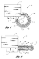
- two plastic blow molding systems identified by 10a and 10b each include a blow molding machine 12 that is supplied plastic preforms 14 from an associated preform supply 16 after heating within an associated oven.
- the blow molding system 10a of Figure 1 has a rotary oven 18a that heats the preforms while the blow molding system 10b of Figure 2 has a linear oven 18b that heats the preforms.
- Each of the ovens 18a and 18b includes a plurality of heater assemblies 20 that are constructed in accordance with the present invention to provide heating of the preforms as is hereinafter more fully described.
- the rotary oven 18a of this embodiment has a conveyor 22a that conveys the preforms 14 in a counterclockwise direction from the supply 16 to the blow molding machine 12 past the heater assemblies 20 to provide heating thereof to a sufficient temperature to permit the blow molding in a conventional manner.
- the preforms 14 will normally be oriented in an upside down position with a lower open end thereof located downwardly and an upper closed end thereof projecting upwardly.
- the conveyor 22a will conventionally rotate the preforms 14 about associated vertical axes in order to provide uniformity of the heating.
- the linear oven 18b includes a conveyor 22b that conveys the preforms 14 from the supply 16 toward the right and then around a U-turn and then back toward the left. During all of such conveyance, the preforms 14 pass by the adjacent heater assemblies 20 to provide heating thereof prior to delivery to the blow molding machine 12 for the blow molding.
- This conveyor 22b like the conveyor of the rotary embodiment will also provide rotation of the preforms while in an upside down orientation in order to provide uniformity of the heating.
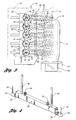
- each heater assembly 20 of both embodiments includes a housing 24 for mounting adjacent the associated conveyor by which the preforms 14 are conveyed along a path of conveyance as previously described in connection with Figures 1 and 2 from a supply of the preforms to the blow molding machine where the heated preforms are blow molded.
- a plurality of elongated heaters 26 of each heater assembly are mounted by the housing 24 and, as shown in Figure 5 , extend along the path of conveyance of the preforms 14 in a parallel relationship to each other.
- the associated conveyor supports the preforms 14 in an upside down orientation with an open dispensing end 30 located in a lower position and with an upper closed end 32 thereof projecting upwardly to adjacent the uppermost heater 26.
- the conveyor will rotate each preform 14 about an associated generally vertical axis A so as to provide uniformity in the heating.
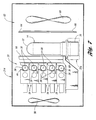
- each heater 26 includes a pair of clip type mounts 34 for mounting an associated elongated bulb 36 that extends along the length of the heater as shown in Figure 5 and has an element 38 ( Figure 3 ) that is energized to irradiate the conveyed preforms 14. Certain of the rays 40 shine directly toward the right as shown in Figure 3 to provide the irradiation of the preforms 14 while certain other rays 42 shine toward the left.
- Each elongated heater 26 also includes a single reflector for embodied by an elongated parabolic reflector 44 that extends along the length of the heater parallel to the associated bulb 36 in a closely spaced relationship.
- the parabolic reflector 44 as disclosed is made of aluminum and at a horizontal line through the bulb element 38 the parabolic reflector is spaced from the bulb 36 about 0.203 to 0.305 mm (0.008 to 0.012 of an inch).
- the parabolic reflector 44 reflects the radiation of the rays 42 back toward the right to irradiate the conveyed preforms 14 in cooperation with the rays 40 that shine directly toward the right.
- the element 38 of the bulb 36 of each heater 26 is located at the focus of its parabolic reflector 44 such that the parabolic reflector reflects the radiation rays 42 in a generally parallel relationship to each other in order to provide controlled heating of the conveyed preforms.
- each heater 26 includes a pair of threaded supports 46 that are suitably secured to mounts 48 supported by the heater assembly housing 24 so as to be closely spaced with each other. Fluid couplings 50 of each heater 26 are connected to cooling tubes 52 through which a cooling fluid flows as to provide cooling of the parabolic reflector 44.
- electrical wires 53 extend from the bulb ends 54 to electrical connectors 55 to provide the energization thereof that energizes the bulb elements as previously described.
- a back cooling fan 56 cools the interior of the heater assembly 20 within whose housing 24 the components described above are mounted.
- the heater assembly 20 also includes a window 58 that is located between the heaters 26 and the conveyed preforms 14.
- This window 58 is preferably made of quartz or any other material that transmits infrared radiation but blocks longer wave radiation so as to provide more uniform heating of the conveyed preforms. More specifically, the infrared radiation penetrates through the outer surface of each preform so as to provide uniformity in the heating between its outer and inner surfaces as compared to longer wavelengths radiation.
- the heater assembly 20 provides uniform heating so that the outside surface of the preform does not have to be overheated in order to provide the inside surface with a sufficiently high temperature for the blow molding.
- the heaters 20 thus allow the use of thicker wall but shorter length preforms of a lighter weight that are more cost effective than heavier preforms.
- the elongated heaters 26 are mounted by the housing 24 in a vertically stacked relationship with the parabolic reflectors 44 of the heaters reflecting radiation rays 42 in a horizontal orientation to provide heating of the conveyed preforms 14.
- the heater assembly 20 includes a lower radiation shield 60 that shields the lower extremity of each conveyed preform 30 at its lower end from irradiation. This radiation shield is fabricated from aluminum.
- the two lowermost bulbs 36 have their elements 38 spaced closer to each other than the spacing between the bulb elements 38 of the two uppermost bulbs 36 and likewise between the bulb elements 38 of the other bulbs so that there is a greater heating in the lower area where greater deformation takes place.
- the heaters 26 have overall heights of 15, 17 or 19 millimeters. The shorter heaters are mounted at the lower positions to thus space the bulb elements closer to each other and thereby provide greater heating.
- each heater assembly 20 of the rotary oven embodiment also cooperates with a back side reflector and cooling unit 62 that is further illustrated in Figure 7 .
- the back side reflector and cooling unit 62 includes a reflector 64 that reflects infrared radiation back toward the performs.
- the reflector 64 has vertical vent formations 66, and the unit also includes a back fan 68 that provides back cooling of the reflector.
- each heater assembly 20 of the linear oven embodiment also includes a back side reflector and cooling unit 70.
- the back side reflector and cooling unit 70 has spaced reflectors 64 with vertical vent formations 66 through which a fan 72 provides back side cooling and ventilation.
Landscapes
- Physics & Mathematics (AREA)
- Thermal Sciences (AREA)
- Engineering & Computer Science (AREA)
- Manufacturing & Machinery (AREA)
- Mechanical Engineering (AREA)
- Blow-Moulding Or Thermoforming Of Plastics Or The Like (AREA)
Applications Claiming Priority (3)
| Application Number | Priority Date | Filing Date | Title |
|---|---|---|---|
| US507609 | 2000-02-21 | ||
| US09/507,609 US6361301B1 (en) | 2000-02-21 | 2000-02-21 | Heater assembly for blow molding plastic preforms |
| PCT/US2001/003860 WO2001062463A1 (en) | 2000-02-21 | 2001-02-06 | Heater assembly for blow molding plastic preforms |
Publications (3)
| Publication Number | Publication Date |
|---|---|
| EP1278619A1 EP1278619A1 (en) | 2003-01-29 |
| EP1278619A4 EP1278619A4 (en) | 2007-12-26 |
| EP1278619B1 true EP1278619B1 (en) | 2010-05-05 |
Family
ID=24019347
Family Applications (1)
| Application Number | Title | Priority Date | Filing Date |
|---|---|---|---|
| EP01908895A Expired - Lifetime EP1278619B1 (en) | 2000-02-21 | 2001-02-06 | Heater assembly for blow molding plastic preforms |
Country Status (12)
| Country | Link |
|---|---|
| US (1) | US6361301B1 (es) |
| EP (1) | EP1278619B1 (es) |
| JP (1) | JP3713238B2 (es) |
| AR (1) | AR027416A1 (es) |
| AT (1) | ATE466711T1 (es) |
| AU (1) | AU769919B2 (es) |
| BR (1) | BR0108521B1 (es) |
| CA (1) | CA2400297C (es) |
| DE (1) | DE60142041D1 (es) |
| MX (1) | MXPA02008015A (es) |
| NZ (1) | NZ520597A (es) |
| WO (1) | WO2001062463A1 (es) |
Cited By (1)
| Publication number | Priority date | Publication date | Assignee | Title |
|---|---|---|---|---|
| EP2444234A2 (de) | 2010-10-22 | 2012-04-25 | Krones AG | Heizvorrichtung zur Temperierung von Vorformlingen |
Families Citing this family (44)
| Publication number | Priority date | Publication date | Assignee | Title |
|---|---|---|---|---|
| DE4337787A1 (de) * | 1993-11-05 | 1995-05-11 | Hoechst Ag | Sauerstoffabhängige Fermentation von Mikroorganismen |
| US6888103B2 (en) | 2002-05-30 | 2005-05-03 | Ball Corporation | Preform preheater |
| FR2863931B1 (fr) * | 2003-12-19 | 2006-03-10 | Sidel Sa | Module de chauffage d'une preforme equipe d'un deflecteur d'air profile de facon aerodynamique et four comportant au moins un tel module |
| FR2863932B1 (fr) * | 2003-12-19 | 2007-07-06 | Sidel Sa | Four de chauffage d'une preforme equipe de deux ventilateurs de refroidissement |
| FR2871403B1 (fr) * | 2004-06-15 | 2007-11-23 | Sidel Sas | Circuit de refroidissement perfectionne pour un four a preformes et procede de mise en oeuvre d'un tel circuit |
| FR2872734B1 (fr) * | 2004-07-08 | 2008-02-22 | Sidel Sa Sa | Four de chauffage d'une preforme comportant un organe de commande du deplacement d'un moyen de chauffage entre des positions indexees |
| US20070284788A1 (en) * | 2004-07-29 | 2007-12-13 | Mitsui Chemicals, Inc. | Process for Producing Hollow Molded Product of Thermoplastic Resin |
| FR2878185B1 (fr) * | 2004-11-22 | 2008-11-07 | Sidel Sas | Procede de fabrication de recipients comprenant une etape de chauffe au moyen d'un faisceau de rayonnement electromagnetique coherent |
| US7425296B2 (en) * | 2004-12-03 | 2008-09-16 | Pressco Technology Inc. | Method and system for wavelength specific thermal irradiation and treatment |
| US10857722B2 (en) * | 2004-12-03 | 2020-12-08 | Pressco Ip Llc | Method and system for laser-based, wavelength specific infrared irradiation treatment |
| FR2907684B1 (fr) * | 2006-10-26 | 2009-12-04 | Sidel Participations | Procede de sterilisation d'une preforme, installation et four pour la fabrication de recipients steriles selon ce procede. |
| FR2913210B1 (fr) * | 2007-03-02 | 2009-05-29 | Sidel Participations | Perfectionnements a la chauffe des matieres plastiques par rayonnement infrarouge |
| FR2917005B1 (fr) * | 2007-06-11 | 2009-08-28 | Sidel Participations | Installation de chauffage des corps de preformes pour le soufflage de recipients |
| DE102007031210A1 (de) * | 2007-07-04 | 2009-01-08 | Krones Ag | Vorrichtung zum Erwärmen von Vorformlingen |
| DE102007031771A1 (de) * | 2007-07-07 | 2009-01-08 | Khs Corpoplast Gmbh & Co. Kg | Verfahren und Vorrichtung zur Blasformung von Behältern |
| DE102009008318A1 (de) * | 2009-02-10 | 2010-08-12 | Krones Ag | Vorrichtung zum Erhitzen von Kunststoffvorformlingen |
| DE102009011361A1 (de) * | 2009-03-05 | 2010-09-09 | Krones Ag | Ofen für Kunststoffvorformlinge mit teiltransparentem Strahler |
| US9162373B2 (en) * | 2009-04-21 | 2015-10-20 | Koninklijke Philips N.V. | Heating system and method of heating a body of a preform |
| DE102009025839A1 (de) * | 2009-05-19 | 2010-11-25 | Krones Ag | Verfahren und Temperiervorrichtung zur Erwärmung von Vorformlingen vor deren Umformung zu Behältern |
| DE102009033902A1 (de) | 2009-07-16 | 2011-01-20 | Khs Corpoplast Gmbh & Co. Kg | Verfahren und Vorrichtung zur Blasformung von Behältern |
| JP5883789B2 (ja) * | 2009-09-15 | 2016-03-15 | コーニンクレッカ フィリップス エヌ ヴェKoninklijke Philips N.V. | プレフォームを加熱する方法 |
| US9000333B2 (en) | 2009-09-23 | 2015-04-07 | Speziallampenfabrik Dr. Fischer Gmbh | Heating installation and reflecting device for a heating installation |
| DE102010015018A1 (de) * | 2010-04-14 | 2011-10-20 | Krones Ag | Strahlerkühlung |
| DE102010018214A1 (de) * | 2010-04-23 | 2011-10-27 | Krones Ag | Heizmodul mit Oberflächenkühlung für Vorformlinge |
| JP2013542549A (ja) * | 2010-05-07 | 2013-11-21 | プレスコ アイピー エルエルシー | コーナキューブによる照射制御 |
| IT1402342B1 (it) * | 2010-10-12 | 2013-08-30 | Sipa Progettazione Automaz | Dispositivo di riscaldamento di preforme in materiale termoplastico. |
| ITRM20110319A1 (it) * | 2011-06-17 | 2012-12-18 | Ne E Automazione S P A | Impianto di riscaldamento preforme di contenitori |
| ITMI20121855A1 (it) * | 2012-10-31 | 2014-05-01 | Smi Spa | Sistema di riscaldamento per forno per preforme |
| EP2813344B1 (en) | 2013-06-10 | 2016-11-16 | Discma AG | Apparatus and method for fabricating containers |
| JP6085894B2 (ja) * | 2013-06-28 | 2017-03-01 | 日精エー・エス・ビー機械株式会社 | プリフォームの加熱装置 |
| DE102014001446A1 (de) * | 2014-01-31 | 2015-08-06 | Kocher-Plastik Maschinenbau Gmbh | Vorrichtung zum Herstellen von Behältererzeugnissen aus Kunststoffmaterial |
| DE102014105675A1 (de) * | 2014-04-23 | 2015-11-12 | Krones Aktiengesellschaft | Vorrichtung und Verfahren zum Erwärmen von Kunststoffvorformlingen |
| DE102014006275A1 (de) * | 2014-05-02 | 2015-11-19 | Khs Corpoplast Gmbh | Verfahren und Vorrichtung zum Temperieren von Vorformlingen |
| FR3022610B1 (fr) | 2014-06-18 | 2016-07-15 | Sidel Participations | Dispositif de chauffage comportant une lampe montee de maniere amovible sur un reflecteur associe |
| DE102014111949A1 (de) * | 2014-08-21 | 2016-02-25 | Krones Aktiengesellschaft | Aufsteckbarer Reflektor |
| DE102015005358A1 (de) * | 2015-04-28 | 2016-11-03 | Khs Corpoplast Gmbh | Verfahren und Aufheizvorrichtung zur Temperaturkonditionierung von Vorformlingen sowie Blasformungsmaschine mit einer solchen Vorrichtung |
| DE102016005273A1 (de) | 2016-04-29 | 2017-11-02 | Khs Corpoplast Gmbh | Vorrichtung und Verfahren zur thermischen Konditionierung von Vorformlingen |
| EP3269531B1 (en) | 2016-12-12 | 2019-05-22 | Sidel Participations | Dehydration circuit for an electromagnetic processing unit of hollow bodies |
| IT201700007077A1 (it) * | 2017-01-24 | 2018-07-24 | Sacmi Imola Sc | Apparecchiatura per il riscaldamento di preforme in materiale termoplastico. |
| WO2018137917A1 (en) * | 2017-01-24 | 2018-08-02 | Solaronics S.A. | Ceramic reflector for infrared lamps |
| DE102017008445A1 (de) * | 2017-09-08 | 2019-03-14 | Khs Corpoplast Gmbh | Hauptreflektor für ein Heizmodul eines Heizkanals einer Formmaschine zur Formung von Behältem aus Vorformlingen |
| CN109228260A (zh) * | 2018-09-30 | 2019-01-18 | 广州华胜塑料制品有限公司 | 一种吹瓶机的温控装置 |
| CN112325635A (zh) * | 2020-10-30 | 2021-02-05 | 江苏新美星包装机械股份有限公司 | 一种用于瓶坯的无菌加温装置 |
| CN115534277A (zh) * | 2022-09-27 | 2022-12-30 | 江苏新美星包装机械股份有限公司 | 一种塑料预型件的加热装置及加热方法 |
Family Cites Families (12)
| Publication number | Priority date | Publication date | Assignee | Title |
|---|---|---|---|---|
| DE3210676C2 (de) * | 1981-03-30 | 1984-12-06 | Cincinnati Milacron Industries, Inc., Cincinnati, Ohio | Verfahen zum Strahlungserwärmen von Vorformlingen |
| KR960001966B1 (ko) * | 1987-06-09 | 1996-02-08 | 도요 세이깐 가부시끼가이샤 | 열가소성 플라스틱병 또는 프리폼의 가열방법과 가열방법에 사용되는 가열체의 온도제어 방법 |
| JPH0622874B2 (ja) * | 1987-06-10 | 1994-03-30 | 東洋製罐株式会社 | 高分子樹脂成型品の加熱方法 |
| DE3823670C2 (de) * | 1988-07-13 | 1999-09-09 | Nissei Asb Machine Co Ltd | Verfahren und Vorrichtung zum Erwärmen von Vorformlingen |
| DE3826841A1 (de) * | 1988-08-06 | 1990-02-08 | Berstorff Gmbh Masch Hermann | Einrichtung zum gleichmaessigen und schnellen aufheizen von sich drehenden vorformlingen fuer nach den streckblasverfahren hergestellte hohlkoerper |
| US4923395A (en) * | 1988-11-16 | 1990-05-08 | Husky Injection Molding Systems Ltd. | Oven for blow molding machine |
| FR2678542B1 (fr) | 1991-07-01 | 1993-10-29 | Sidel | Procede et installation pour le chauffage, par rayonnement infrarouge, de preformes en matiere plastique, notamment en pet, destinees a la fabrication de recipients. |
| FR2689442B1 (fr) * | 1992-04-03 | 1995-06-23 | Sidel Sa | Procede de conditionnement thermique de preformes en matieres thermoplastiques et dispositif pour la mise en óoeuvre de ce procede. |
| FR2703944B1 (fr) | 1993-04-15 | 1995-06-23 | Sidel Sa | Procédé et installation pour le traitement thermique du corps d'une préforme en matériau thermoplastique. |
| US5549468A (en) * | 1994-10-19 | 1996-08-27 | Constar Plastics Inc. | Heating lamp assembly |
| FR2732924B1 (fr) * | 1995-04-12 | 1997-06-13 | Sidel Sa | Procede et dispositif de chauffage selectif d'une preforme de recipient |
| DE19724621B4 (de) * | 1997-06-11 | 2004-05-06 | Sig Corpoplast Gmbh & Co. Kg | Verfahren und Vorrichtung zur Temperierung von Vorformlingen |
-
2000
- 2000-02-21 US US09/507,609 patent/US6361301B1/en not_active Expired - Lifetime
-
2001
- 2001-02-06 NZ NZ520597A patent/NZ520597A/xx unknown
- 2001-02-06 EP EP01908895A patent/EP1278619B1/en not_active Expired - Lifetime
- 2001-02-06 WO PCT/US2001/003860 patent/WO2001062463A1/en active IP Right Grant
- 2001-02-06 BR BRPI0108521-2A patent/BR0108521B1/pt not_active IP Right Cessation
- 2001-02-06 CA CA002400297A patent/CA2400297C/en not_active Expired - Lifetime
- 2001-02-06 DE DE60142041T patent/DE60142041D1/de not_active Expired - Lifetime
- 2001-02-06 JP JP2001561509A patent/JP3713238B2/ja not_active Expired - Lifetime
- 2001-02-06 AU AU36710/01A patent/AU769919B2/en not_active Ceased
- 2001-02-06 MX MXPA02008015A patent/MXPA02008015A/es active IP Right Grant
- 2001-02-06 AT AT01908895T patent/ATE466711T1/de active
- 2001-02-13 AR ARP010100639A patent/AR027416A1/es active IP Right Grant
Cited By (4)
| Publication number | Priority date | Publication date | Assignee | Title |
|---|---|---|---|---|
| EP2444234A2 (de) | 2010-10-22 | 2012-04-25 | Krones AG | Heizvorrichtung zur Temperierung von Vorformlingen |
| DE102010049136A1 (de) | 2010-10-22 | 2012-04-26 | Krones Aktiengesellschaft | Heizvorrichtung zur Temperierung von Vorformlingen |
| US8774611B2 (en) | 2010-10-22 | 2014-07-08 | Krones Ag | Heating device for the tempering of preforms |
| US9084293B2 (en) | 2010-10-22 | 2015-07-14 | Krones Aktiengesellschaft | Heating device for the tempering of preforms |
Also Published As
| Publication number | Publication date |
|---|---|
| EP1278619A1 (en) | 2003-01-29 |
| WO2001062463A1 (en) | 2001-08-30 |
| BR0108521B1 (pt) | 2009-08-11 |
| NZ520597A (en) | 2002-11-26 |
| DE60142041D1 (en) | 2010-06-17 |
| BR0108521A (pt) | 2003-04-15 |
| AU769919B2 (en) | 2004-02-12 |
| EP1278619A4 (en) | 2007-12-26 |
| CA2400297A1 (en) | 2001-08-30 |
| US6361301B1 (en) | 2002-03-26 |
| JP2003523848A (ja) | 2003-08-12 |
| CA2400297C (en) | 2005-06-14 |
| AR027416A1 (es) | 2003-03-26 |
| AU3671001A (en) | 2001-09-03 |
| JP3713238B2 (ja) | 2005-11-09 |
| ATE466711T1 (de) | 2010-05-15 |
| MXPA02008015A (es) | 2003-01-28 |
Similar Documents
| Publication | Publication Date | Title |
|---|---|---|
| EP1278619B1 (en) | Heater assembly for blow molding plastic preforms | |
| EP2139667B1 (en) | Method of heating preforms for the manufacture of containers, and heater device | |
| RU2241930C2 (ru) | Усовершенствованная печь инфракрасного нагрева для кондиционирования предварительно отформованных пластмассовых заготовок | |
| CN102548722B (zh) | 加热设备和用于加热设备的反射装置 | |
| US4605839A (en) | Dual parison heating reflector and method | |
| EP2727706B1 (en) | Heating system for oven for preforms | |
| EP2483046B1 (en) | Arrangement of a counter reflector device for use in heating an object, installation and method of heating | |
| US9004896B2 (en) | Oven for plastic preforms with partly transparent radiator | |
| CN207327572U (zh) | 用于加热塑料预制件的设备 | |
| CN108698307B (zh) | 用于热处理预制件的设备和方法 | |
| CN105383046A (zh) | 用于加热塑料型坯的设备和加热装置 | |
| CN104149322A (zh) | 用于红外加热塑料预成型件的设备 | |
| CN106345667A (zh) | Uv固化炉 | |
| US8936746B2 (en) | Bracket for a quartz lamp of a blow molding machine | |
| CN1984766B (zh) | 饱和聚酯空心体的加热晶化装置及其加热方法 | |
| KR200333837Y1 (ko) | 페트병 목부분의 가열구조 | |
| JP4126090B2 (ja) | プリフォームの口頸部を結晶化する方法 | |
| JP4565733B2 (ja) | 予備加熱装置 | |
| KR100541184B1 (ko) | 페트병 목부분의 가열구조를 결정하는 방법과, 이에 의한가열구조 | |
| CN105034329A (zh) | 用于加热塑料坯的设备和方法 | |
| CN114786919A (zh) | 具有预型件颈部保护装置的塑料预型件加热器 |
Legal Events
| Date | Code | Title | Description |
|---|---|---|---|
| PUAI | Public reference made under article 153(3) epc to a published international application that has entered the european phase |
Free format text: ORIGINAL CODE: 0009012 |
|
| 17P | Request for examination filed |
Effective date: 20020819 |
|
| AK | Designated contracting states |
Designated state(s): AT BE CH CY DE DK ES FI FR GB GR IE IT LI LU MC NL PT SE TR |
|
| AX | Request for extension of the european patent |
Extension state: AL LT LV MK RO SI |
|
| A4 | Supplementary search report drawn up and despatched |
Effective date: 20071123 |
|
| 17Q | First examination report despatched |
Effective date: 20080808 |
|
| GRAP | Despatch of communication of intention to grant a patent |
Free format text: ORIGINAL CODE: EPIDOSNIGR1 |
|
| GRAS | Grant fee paid |
Free format text: ORIGINAL CODE: EPIDOSNIGR3 |
|
| GRAA | (expected) grant |
Free format text: ORIGINAL CODE: 0009210 |
|
| AK | Designated contracting states |
Kind code of ref document: B1 Designated state(s): AT BE CH CY DE DK ES FI FR GB GR IE IT LI LU MC NL PT SE TR |
|
| REG | Reference to a national code |
Ref country code: GB Ref legal event code: FG4D |
|
| REG | Reference to a national code |
Ref country code: CH Ref legal event code: NV Representative=s name: ISLER & PEDRAZZINI AG Ref country code: CH Ref legal event code: EP |
|
| REG | Reference to a national code |
Ref country code: IE Ref legal event code: FG4D |
|
| REG | Reference to a national code |
Ref country code: CH Ref legal event code: PFA Owner name: PLASTIPAK PACKAGING, INC. Free format text: PLASTIPAK PACKAGING INC.#P.O. BOX 2500 C 9135 GENERAL COURT#PLYMOUTH MICHIGAN 48170 (US) -TRANSFER TO- PLASTIPAK PACKAGING, INC.#P.O. BOX 2500 C 41605 ANN ARBOR ROAD,#PLYMOUTH, MICHIGAN, 48170 (US) |
|
| REF | Corresponds to: |
Ref document number: 60142041 Country of ref document: DE Date of ref document: 20100617 Kind code of ref document: P |
|
| REG | Reference to a national code |
Ref country code: NL Ref legal event code: T3 |
|
| REG | Reference to a national code |
Ref country code: FR Ref legal event code: CA |
|
| PG25 | Lapsed in a contracting state [announced via postgrant information from national office to epo] |
Ref country code: SE Free format text: LAPSE BECAUSE OF FAILURE TO SUBMIT A TRANSLATION OF THE DESCRIPTION OR TO PAY THE FEE WITHIN THE PRESCRIBED TIME-LIMIT Effective date: 20100505 Ref country code: ES Free format text: LAPSE BECAUSE OF FAILURE TO SUBMIT A TRANSLATION OF THE DESCRIPTION OR TO PAY THE FEE WITHIN THE PRESCRIBED TIME-LIMIT Effective date: 20100816 |
|
| PG25 | Lapsed in a contracting state [announced via postgrant information from national office to epo] |
Ref country code: FI Free format text: LAPSE BECAUSE OF FAILURE TO SUBMIT A TRANSLATION OF THE DESCRIPTION OR TO PAY THE FEE WITHIN THE PRESCRIBED TIME-LIMIT Effective date: 20100505 |
|
| PG25 | Lapsed in a contracting state [announced via postgrant information from national office to epo] |
Ref country code: GR Free format text: LAPSE BECAUSE OF FAILURE TO SUBMIT A TRANSLATION OF THE DESCRIPTION OR TO PAY THE FEE WITHIN THE PRESCRIBED TIME-LIMIT Effective date: 20100806 Ref country code: CY Free format text: LAPSE BECAUSE OF FAILURE TO SUBMIT A TRANSLATION OF THE DESCRIPTION OR TO PAY THE FEE WITHIN THE PRESCRIBED TIME-LIMIT Effective date: 20100505 |
|
| PG25 | Lapsed in a contracting state [announced via postgrant information from national office to epo] |
Ref country code: DK Free format text: LAPSE BECAUSE OF FAILURE TO SUBMIT A TRANSLATION OF THE DESCRIPTION OR TO PAY THE FEE WITHIN THE PRESCRIBED TIME-LIMIT Effective date: 20100505 Ref country code: PT Free format text: LAPSE BECAUSE OF FAILURE TO SUBMIT A TRANSLATION OF THE DESCRIPTION OR TO PAY THE FEE WITHIN THE PRESCRIBED TIME-LIMIT Effective date: 20100906 |
|
| PLBE | No opposition filed within time limit |
Free format text: ORIGINAL CODE: 0009261 |
|
| STAA | Information on the status of an ep patent application or granted ep patent |
Free format text: STATUS: NO OPPOSITION FILED WITHIN TIME LIMIT |
|
| 26N | No opposition filed |
Effective date: 20110208 |
|
| REG | Reference to a national code |
Ref country code: DE Ref legal event code: R097 Ref document number: 60142041 Country of ref document: DE Effective date: 20110207 |
|
| PG25 | Lapsed in a contracting state [announced via postgrant information from national office to epo] |
Ref country code: MC Free format text: LAPSE BECAUSE OF NON-PAYMENT OF DUE FEES Effective date: 20110228 |
|
| REG | Reference to a national code |
Ref country code: IE Ref legal event code: MM4A |
|
| PG25 | Lapsed in a contracting state [announced via postgrant information from national office to epo] |
Ref country code: IE Free format text: LAPSE BECAUSE OF NON-PAYMENT OF DUE FEES Effective date: 20110206 |
|
| PGFP | Annual fee paid to national office [announced via postgrant information from national office to epo] |
Ref country code: LU Payment date: 20130228 Year of fee payment: 13 |
|
| PGFP | Annual fee paid to national office [announced via postgrant information from national office to epo] |
Ref country code: CH Payment date: 20130129 Year of fee payment: 13 |
|
| PGFP | Annual fee paid to national office [announced via postgrant information from national office to epo] |
Ref country code: NL Payment date: 20130212 Year of fee payment: 13 |
|
| PGFP | Annual fee paid to national office [announced via postgrant information from national office to epo] |
Ref country code: AT Payment date: 20130128 Year of fee payment: 13 |
|
| PGFP | Annual fee paid to national office [announced via postgrant information from national office to epo] |
Ref country code: BE Payment date: 20130305 Year of fee payment: 13 |
|
| PG25 | Lapsed in a contracting state [announced via postgrant information from national office to epo] |
Ref country code: TR Free format text: LAPSE BECAUSE OF FAILURE TO SUBMIT A TRANSLATION OF THE DESCRIPTION OR TO PAY THE FEE WITHIN THE PRESCRIBED TIME-LIMIT Effective date: 20100505 |
|
| BERE | Be: lapsed |
Owner name: PLASTIPAK PACKAGING INC. Effective date: 20140228 |
|
| REG | Reference to a national code |
Ref country code: NL Ref legal event code: V1 Effective date: 20140901 |
|
| PG25 | Lapsed in a contracting state [announced via postgrant information from national office to epo] |
Ref country code: LU Free format text: LAPSE BECAUSE OF NON-PAYMENT OF DUE FEES Effective date: 20140206 |
|
| REG | Reference to a national code |
Ref country code: CH Ref legal event code: PL |
|
| REG | Reference to a national code |
Ref country code: AT Ref legal event code: MM01 Ref document number: 466711 Country of ref document: AT Kind code of ref document: T Effective date: 20140206 |
|
| PG25 | Lapsed in a contracting state [announced via postgrant information from national office to epo] |
Ref country code: CH Free format text: LAPSE BECAUSE OF NON-PAYMENT OF DUE FEES Effective date: 20140228 Ref country code: LI Free format text: LAPSE BECAUSE OF NON-PAYMENT OF DUE FEES Effective date: 20140228 Ref country code: NL Free format text: LAPSE BECAUSE OF NON-PAYMENT OF DUE FEES Effective date: 20140901 |
|
| PG25 | Lapsed in a contracting state [announced via postgrant information from national office to epo] |
Ref country code: AT Free format text: LAPSE BECAUSE OF NON-PAYMENT OF DUE FEES Effective date: 20140206 |
|
| PG25 | Lapsed in a contracting state [announced via postgrant information from national office to epo] |
Ref country code: BE Free format text: LAPSE BECAUSE OF NON-PAYMENT OF DUE FEES Effective date: 20140228 |
|
| REG | Reference to a national code |
Ref country code: DE Ref legal event code: R082 Ref document number: 60142041 Country of ref document: DE Representative=s name: PATENTANWAELTE WEICKMANN & WEICKMANN, DE Ref country code: DE Ref legal event code: R082 Ref document number: 60142041 Country of ref document: DE Representative=s name: WEICKMANN & WEICKMANN PATENTANWAELTE - RECHTSA, DE Ref country code: DE Ref legal event code: R082 Ref document number: 60142041 Country of ref document: DE Representative=s name: WEICKMANN & WEICKMANN PATENT- UND RECHTSANWAEL, DE |
|
| REG | Reference to a national code |
Ref country code: FR Ref legal event code: PLFP Year of fee payment: 16 |
|
| PGFP | Annual fee paid to national office [announced via postgrant information from national office to epo] |
Ref country code: IT Payment date: 20160210 Year of fee payment: 16 Ref country code: DE Payment date: 20160302 Year of fee payment: 16 |
|
| PGFP | Annual fee paid to national office [announced via postgrant information from national office to epo] |
Ref country code: FR Payment date: 20160125 Year of fee payment: 16 Ref country code: GB Payment date: 20160127 Year of fee payment: 16 |
|
| REG | Reference to a national code |
Ref country code: DE Ref legal event code: R119 Ref document number: 60142041 Country of ref document: DE |
|
| GBPC | Gb: european patent ceased through non-payment of renewal fee |
Effective date: 20170206 |
|
| REG | Reference to a national code |
Ref country code: FR Ref legal event code: ST Effective date: 20171031 |
|
| PG25 | Lapsed in a contracting state [announced via postgrant information from national office to epo] |
Ref country code: FR Free format text: LAPSE BECAUSE OF NON-PAYMENT OF DUE FEES Effective date: 20170228 Ref country code: DE Free format text: LAPSE BECAUSE OF NON-PAYMENT OF DUE FEES Effective date: 20170901 |
|
| PG25 | Lapsed in a contracting state [announced via postgrant information from national office to epo] |
Ref country code: IT Free format text: LAPSE BECAUSE OF NON-PAYMENT OF DUE FEES Effective date: 20170206 Ref country code: GB Free format text: LAPSE BECAUSE OF NON-PAYMENT OF DUE FEES Effective date: 20170206 |