EP1277983B1 - Brake device & method using Ni-W alloy plating - Google Patents
Brake device & method using Ni-W alloy plating Download PDFInfo
- Publication number
- EP1277983B1 EP1277983B1 EP02015644A EP02015644A EP1277983B1 EP 1277983 B1 EP1277983 B1 EP 1277983B1 EP 02015644 A EP02015644 A EP 02015644A EP 02015644 A EP02015644 A EP 02015644A EP 1277983 B1 EP1277983 B1 EP 1277983B1
- Authority
- EP
- European Patent Office
- Prior art keywords
- layer
- braking
- nickel
- braking device
- tungsten alloy
- Prior art date
- Legal status (The legal status is an assumption and is not a legal conclusion. Google has not performed a legal analysis and makes no representation as to the accuracy of the status listed.)
- Expired - Lifetime
Links
- 229910001080 W alloy Inorganic materials 0.000 title claims abstract description 61
- 238000007747 plating Methods 0.000 title claims description 65
- 238000000034 method Methods 0.000 title description 15
- MOWMLACGTDMJRV-UHFFFAOYSA-N nickel tungsten Chemical compound [Ni].[W] MOWMLACGTDMJRV-UHFFFAOYSA-N 0.000 claims abstract description 63
- 239000011159 matrix material Substances 0.000 claims abstract description 36
- PXHVJJICTQNCMI-UHFFFAOYSA-N Nickel Chemical compound [Ni] PXHVJJICTQNCMI-UHFFFAOYSA-N 0.000 claims abstract description 33
- 239000010949 copper Substances 0.000 claims abstract description 20
- 229910052751 metal Inorganic materials 0.000 claims abstract description 20
- 239000002184 metal Substances 0.000 claims abstract description 20
- 229910052759 nickel Inorganic materials 0.000 claims abstract description 19
- 229910052802 copper Inorganic materials 0.000 claims abstract description 17
- RYGMFSIKBFXOCR-UHFFFAOYSA-N Copper Chemical compound [Cu] RYGMFSIKBFXOCR-UHFFFAOYSA-N 0.000 claims abstract description 12
- 238000004519 manufacturing process Methods 0.000 claims description 16
- 229910045601 alloy Inorganic materials 0.000 claims description 10
- 239000000956 alloy Substances 0.000 claims description 10
- XEEYBQQBJWHFJM-UHFFFAOYSA-N iron Substances [Fe] XEEYBQQBJWHFJM-UHFFFAOYSA-N 0.000 claims description 9
- 229910052742 iron Inorganic materials 0.000 claims description 7
- 229910052718 tin Inorganic materials 0.000 claims description 7
- 229910052698 phosphorus Inorganic materials 0.000 claims description 6
- 229910001256 stainless steel alloy Inorganic materials 0.000 claims description 6
- 229910052725 zinc Inorganic materials 0.000 claims description 6
- 229910052782 aluminium Inorganic materials 0.000 claims description 5
- 229910052797 bismuth Inorganic materials 0.000 claims description 5
- 229910052804 chromium Inorganic materials 0.000 claims description 5
- 229910052748 manganese Inorganic materials 0.000 claims description 5
- 229910052709 silver Inorganic materials 0.000 claims description 5
- 239000010944 silver (metal) Substances 0.000 claims description 5
- 239000011135 tin Substances 0.000 claims description 5
- 239000011701 zinc Substances 0.000 claims description 5
- 150000002739 metals Chemical class 0.000 claims description 4
- 229910000838 Al alloy Inorganic materials 0.000 claims description 3
- 229910000861 Mg alloy Inorganic materials 0.000 claims description 2
- 229910001069 Ti alloy Inorganic materials 0.000 claims description 2
- 239000010410 layer Substances 0.000 description 104
- 238000012360 testing method Methods 0.000 description 87
- 238000010438 heat treatment Methods 0.000 description 17
- XLYOFNOQVPJJNP-UHFFFAOYSA-N water Substances O XLYOFNOQVPJJNP-UHFFFAOYSA-N 0.000 description 15
- 238000005260 corrosion Methods 0.000 description 13
- 230000007797 corrosion Effects 0.000 description 13
- 230000000694 effects Effects 0.000 description 13
- 230000000052 comparative effect Effects 0.000 description 11
- 238000005562 fading Methods 0.000 description 11
- 230000008569 process Effects 0.000 description 11
- 238000011156 evaluation Methods 0.000 description 7
- 230000007246 mechanism Effects 0.000 description 7
- 238000002845 discoloration Methods 0.000 description 6
- 239000000463 material Substances 0.000 description 6
- 230000015572 biosynthetic process Effects 0.000 description 5
- 238000009736 wetting Methods 0.000 description 5
- OKTJSMMVPCPJKN-UHFFFAOYSA-N Carbon Chemical compound [C] OKTJSMMVPCPJKN-UHFFFAOYSA-N 0.000 description 3
- 230000001965 increasing effect Effects 0.000 description 3
- 230000013011 mating Effects 0.000 description 3
- 238000007254 oxidation reaction Methods 0.000 description 3
- 230000004044 response Effects 0.000 description 3
- 238000010998 test method Methods 0.000 description 3
- 229910001295 No alloy Inorganic materials 0.000 description 2
- 229910020938 Sn-Ni Inorganic materials 0.000 description 2
- 229910008937 Sn—Ni Inorganic materials 0.000 description 2
- QAOWNCQODCNURD-UHFFFAOYSA-N Sulfuric acid Chemical compound OS(O)(=O)=O QAOWNCQODCNURD-UHFFFAOYSA-N 0.000 description 2
- 229910052799 carbon Inorganic materials 0.000 description 2
- 230000008859 change Effects 0.000 description 2
- 230000002708 enhancing effect Effects 0.000 description 2
- 239000012530 fluid Substances 0.000 description 2
- 230000006870 function Effects 0.000 description 2
- 230000017525 heat dissipation Effects 0.000 description 2
- 238000012423 maintenance Methods 0.000 description 2
- 239000000203 mixture Substances 0.000 description 2
- 230000003647 oxidation Effects 0.000 description 2
- 238000003825 pressing Methods 0.000 description 2
- 239000002344 surface layer Substances 0.000 description 2
- 230000003746 surface roughness Effects 0.000 description 2
- 229910052721 tungsten Inorganic materials 0.000 description 2
- 208000032544 Cicatrix Diseases 0.000 description 1
- FYYHWMGAXLPEAU-UHFFFAOYSA-N Magnesium Chemical compound [Mg] FYYHWMGAXLPEAU-UHFFFAOYSA-N 0.000 description 1
- 229910000990 Ni alloy Inorganic materials 0.000 description 1
- 229910000831 Steel Inorganic materials 0.000 description 1
- 230000009471 action Effects 0.000 description 1
- 230000006978 adaptation Effects 0.000 description 1
- 230000002730 additional effect Effects 0.000 description 1
- 230000004888 barrier function Effects 0.000 description 1
- 230000008901 benefit Effects 0.000 description 1
- 238000006243 chemical reaction Methods 0.000 description 1
- 239000002131 composite material Substances 0.000 description 1
- 239000004020 conductor Substances 0.000 description 1
- 238000007796 conventional method Methods 0.000 description 1
- 238000001816 cooling Methods 0.000 description 1
- 238000010586 diagram Methods 0.000 description 1
- XPPKVPWEQAFLFU-UHFFFAOYSA-J diphosphate(4-) Chemical compound [O-]P([O-])(=O)OP([O-])([O-])=O XPPKVPWEQAFLFU-UHFFFAOYSA-J 0.000 description 1
- 235000011180 diphosphates Nutrition 0.000 description 1
- 238000009713 electroplating Methods 0.000 description 1
- 238000002474 experimental method Methods 0.000 description 1
- 239000010419 fine particle Substances 0.000 description 1
- 239000002783 friction material Substances 0.000 description 1
- 229910002804 graphite Inorganic materials 0.000 description 1
- 239000010439 graphite Substances 0.000 description 1
- 238000007373 indentation Methods 0.000 description 1
- 238000003780 insertion Methods 0.000 description 1
- 230000037431 insertion Effects 0.000 description 1
- 229910052749 magnesium Inorganic materials 0.000 description 1
- 239000011777 magnesium Substances 0.000 description 1
- 150000001247 metal acetylides Chemical class 0.000 description 1
- 239000007769 metal material Substances 0.000 description 1
- 238000012986 modification Methods 0.000 description 1
- 230000004048 modification Effects 0.000 description 1
- 150000002815 nickel Chemical class 0.000 description 1
- 150000004767 nitrides Chemical class 0.000 description 1
- -1 oxides Chemical class 0.000 description 1
- 208000014451 palmoplantar keratoderma and congenital alopecia 2 Diseases 0.000 description 1
- 238000002360 preparation method Methods 0.000 description 1
- 230000001737 promoting effect Effects 0.000 description 1
- 239000011241 protective layer Substances 0.000 description 1
- 230000009467 reduction Effects 0.000 description 1
- 239000005871 repellent Substances 0.000 description 1
- 230000004043 responsiveness Effects 0.000 description 1
- 230000000630 rising effect Effects 0.000 description 1
- 150000003839 salts Chemical class 0.000 description 1
- 231100000241 scar Toxicity 0.000 description 1
- 230000037387 scars Effects 0.000 description 1
- 230000037152 sensory function Effects 0.000 description 1
- 238000003892 spreading Methods 0.000 description 1
- 229910001220 stainless steel Inorganic materials 0.000 description 1
- 239000010935 stainless steel Substances 0.000 description 1
- 239000010959 steel Substances 0.000 description 1
- 239000000126 substance Substances 0.000 description 1
- 239000000725 suspension Substances 0.000 description 1
- 230000002195 synergetic effect Effects 0.000 description 1
- WFKWXMTUELFFGS-UHFFFAOYSA-N tungsten Chemical compound [W] WFKWXMTUELFFGS-UHFFFAOYSA-N 0.000 description 1
- 239000010937 tungsten Substances 0.000 description 1
- 238000011179 visual inspection Methods 0.000 description 1
Images


Classifications
-
- F—MECHANICAL ENGINEERING; LIGHTING; HEATING; WEAPONS; BLASTING
- F16—ENGINEERING ELEMENTS AND UNITS; GENERAL MEASURES FOR PRODUCING AND MAINTAINING EFFECTIVE FUNCTIONING OF MACHINES OR INSTALLATIONS; THERMAL INSULATION IN GENERAL
- F16D—COUPLINGS FOR TRANSMITTING ROTATION; CLUTCHES; BRAKES
- F16D69/00—Friction linings; Attachment thereof; Selection of coacting friction substances or surfaces
- F16D69/02—Compositions of linings; Methods of manufacturing
-
- B—PERFORMING OPERATIONS; TRANSPORTING
- B62—LAND VEHICLES FOR TRAVELLING OTHERWISE THAN ON RAILS
- B62L—BRAKES SPECIALLY ADAPTED FOR CYCLES
- B62L1/00—Brakes; Arrangements thereof
-
- F—MECHANICAL ENGINEERING; LIGHTING; HEATING; WEAPONS; BLASTING
- F16—ENGINEERING ELEMENTS AND UNITS; GENERAL MEASURES FOR PRODUCING AND MAINTAINING EFFECTIVE FUNCTIONING OF MACHINES OR INSTALLATIONS; THERMAL INSULATION IN GENERAL
- F16D—COUPLINGS FOR TRANSMITTING ROTATION; CLUTCHES; BRAKES
- F16D65/00—Parts or details
- F16D65/0025—Rust- or corrosion-preventing means
-
- F—MECHANICAL ENGINEERING; LIGHTING; HEATING; WEAPONS; BLASTING
- F16—ENGINEERING ELEMENTS AND UNITS; GENERAL MEASURES FOR PRODUCING AND MAINTAINING EFFECTIVE FUNCTIONING OF MACHINES OR INSTALLATIONS; THERMAL INSULATION IN GENERAL
- F16D—COUPLINGS FOR TRANSMITTING ROTATION; CLUTCHES; BRAKES
- F16D65/00—Parts or details
- F16D65/02—Braking members; Mounting thereof
- F16D65/12—Discs; Drums for disc brakes
-
- F—MECHANICAL ENGINEERING; LIGHTING; HEATING; WEAPONS; BLASTING
- F16—ENGINEERING ELEMENTS AND UNITS; GENERAL MEASURES FOR PRODUCING AND MAINTAINING EFFECTIVE FUNCTIONING OF MACHINES OR INSTALLATIONS; THERMAL INSULATION IN GENERAL
- F16D—COUPLINGS FOR TRANSMITTING ROTATION; CLUTCHES; BRAKES
- F16D69/00—Friction linings; Attachment thereof; Selection of coacting friction substances or surfaces
- F16D69/02—Compositions of linings; Methods of manufacturing
- F16D69/027—Compositions based on metals or inorganic oxides
-
- F—MECHANICAL ENGINEERING; LIGHTING; HEATING; WEAPONS; BLASTING
- F16—ENGINEERING ELEMENTS AND UNITS; GENERAL MEASURES FOR PRODUCING AND MAINTAINING EFFECTIVE FUNCTIONING OF MACHINES OR INSTALLATIONS; THERMAL INSULATION IN GENERAL
- F16D—COUPLINGS FOR TRANSMITTING ROTATION; CLUTCHES; BRAKES
- F16D65/00—Parts or details
- F16D65/02—Braking members; Mounting thereof
- F16D2065/13—Parts or details of discs or drums
- F16D2065/1304—Structure
- F16D2065/132—Structure layered
-
- F—MECHANICAL ENGINEERING; LIGHTING; HEATING; WEAPONS; BLASTING
- F16—ENGINEERING ELEMENTS AND UNITS; GENERAL MEASURES FOR PRODUCING AND MAINTAINING EFFECTIVE FUNCTIONING OF MACHINES OR INSTALLATIONS; THERMAL INSULATION IN GENERAL
- F16D—COUPLINGS FOR TRANSMITTING ROTATION; CLUTCHES; BRAKES
- F16D2200/00—Materials; Production methods therefor
- F16D2200/0004—Materials; Production methods therefor metallic
- F16D2200/0008—Ferro
- F16D2200/0017—Ferro corrosion-resistant
-
- F—MECHANICAL ENGINEERING; LIGHTING; HEATING; WEAPONS; BLASTING
- F16—ENGINEERING ELEMENTS AND UNITS; GENERAL MEASURES FOR PRODUCING AND MAINTAINING EFFECTIVE FUNCTIONING OF MACHINES OR INSTALLATIONS; THERMAL INSULATION IN GENERAL
- F16D—COUPLINGS FOR TRANSMITTING ROTATION; CLUTCHES; BRAKES
- F16D2250/00—Manufacturing; Assembly
- F16D2250/0038—Surface treatment
- F16D2250/0046—Coating
Definitions
- the present invention is directed to braking devices and, more particularly, to a braking member and to a method of manufacturing such a braking member.
- Braking devices for braking a moving object such as a vehicle or the like by means of frictional force are generally equipped with a moving member that moves with the object and a friction member which applies a braking force by pressing against the moving member.
- a vehicle disk brake ordinarily comprises a metal disk rotor that rotates integrally with the vehicle wheel, and brake pads that can be pressed against the disk rotor.
- a vehicle drum brake ordinarily comprises a brake drum that rotates integrally with the vehicle wheel, and brake shoes that can be pressed against the brake drum.
- fading in which the braking force drops because of heat generated by friction.
- Conventional methods used to reduce such fading include enhancing heat dissipation characteristics of the braking device by modifying the material or shape of friction members such as brake pads, brake shoes or the like; enhancing heat dissipation characteristics of the braking device by using a carbon or ventilated type disk rotor, and by preventing the temperature of metal moving members from rising to a level where fading occurs.
- severe operating conditions such as those encountered in bicycle downhill racing, a rise in the temperature of the moving members cannot be prevented using such conventional countermeasures. As a result, fading cannot be sufficiently suppressed under such harsh conditions.
- Another problem with conventional braking devices is a drop in the braking force due to wetting of the disk rotor or brake drum by water. More specifically, when such wetting with water occurs and the water adheres to the frictional members or to the moving member, then the frictional force drops, thus leading to a drop in the braking force.
- Document D2 DE 4321713 A1 discloses a composite disc brake rotor and a process for its manufacture.
- the cover of the disc break is comprised of a self-lubricating thermal conducting cover which increases the wear resistance of the disc break arrangement.
- the friction surface of this disc break is made of steel, and the layer arrangement of the disc break may include a nickel alloy as a thermal barrier.
- the present invention is directed to a braking member and to a method of manufacturing such a braking member, wherein the braking member exhibits better braking characteristics than conventional braking members.
- a braking member may have better braking characteristics under high temperature and/or wet conditions, for example.
- a braking member having a friction surface includes a matrix and a nickel-tungsten alloy layer disposed between the matrix and the friction surface. If desired, the nickel-tungsten alloy layer may form the friction surface. In a more specific embodiment, the braking member may include an additional nickel or copper layer, and such a layer may be disposed between the nickel-tungsten alloy layer and the matrix. A further metal layer may be disposed between the nickel-tungsten alloy layer and the friction surface. If desired, the further metal layer may be an elemental or alloy layer selected from the group comprising Sn, Cu, Zn, Ni, Ag, Fe, Al, P, Mn, Bi and Cr, and the further metal layer may form the friction surface.
- a method of making a braking member having a friction surface comprises the steps of providing a matrix of the braking member and forming a nickel-tungsten alloy layer between the matrix and the friction surface. If desired, the nickel-tungsten alloy layer may form the friction surface. In a more specific embodiment, an additional nickel or copper layer may be formed on the braking member, and such a layer may be disposed between the nickel-tungsten alloy layer and the matrix. A further metal layer may be formed between the nickel-tungsten alloy layer and the friction surface. If desired, the further metal layer may be an elemental or alloy layer selected from the group comprising Sn, Cu, Zn, Ni, Ag, Fe, Al, P, Mn, Bi and Cr, and the further metal layer may form the friction surface.
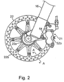
- Fig. 1 is a side view of a front portion of a bicycle 10 that includes a particular embodiment of a braking device 12 (e.g., a disk braking device) according to the present invention.
- Bicycle 10 is a conventional universally known bicycle, and it comprises a bicycle frame 14 which has handlebars 15, front and rear forks 16 (only the front fork is shown in the figures), front and rear wheels 17 (only the front wheel is shown in the figures), and a driving device that includes sprockets and a chain (not shown).
- the disk braking device 12 comprises a brake caliper 21 mounted on the front fork 16 (which is equipped with a double crown type suspension), a disk rotor 22 and a brake actuating mechanism 23.
- the brake caliper 21 is attached to the front fork 16 of the bicycle 10 in a position that is in close proximity to the disk rotor 22 so that the caliper 21 can apply a frictional force to the disk rotor 22 to stop the rotation of the disk rotor 22.
- the brake caliper 21 is equipped with a housing 50 and a piston unit 51.
- the housing 50 is constructed from a heat-conducting material such as an aluminum alloy or the like, and it comprises a first housing member 52a and a second housing member 52b that are joined together by bolts (not shown). Both housing members 52a and 52b have substantially the same shape. Furthermore, the second housing member 52b has a flange that extends outward and forms an attachment member 54 that is used to fasten the brake caliper 21 to the front fork 16 by means of bolts. When housing members 52a and 52b are assembled together, a brake slot is formed between the two housing members, and the disk rotor 22 can be accommodated in this brake slot.
- a brake slot is formed between the two housing members, and the disk rotor 22 can be accommodated in this brake slot.
- circular cylinder parts 57a and 57b each of which accommodates two pistons 74, and oil passages 58a and 58b which are used to supply brake oil to the respective cylinder parts 57a and 57b, are formed in the two housing members 52a and 52b.
- the hydraulic piping 86 of the brake actuating mechanism 23 is connected to the second housing member 52b so that brake oil is supplied to both housing members 52a and 52b.Thus, brake oil supplied from the brake actuating mechanism 23 flows into the second housing member 52b and into the oil passages 58a and 58b so that the piston unit 51 is actuated.
- Brake actuating mechanism 23 is integrally attached to the right-end portion of the handlebars 15.
- Brake actuating mechanism 23 includes a brake lever assembly 80, a master cylinder 81, a master piston 82, an oil tank 83, a bracket 84, and a lever part 85.
- Bracket 84 is mounted on the handlebars 15, and lever part 85 is mounted on bracket 84 so that lever part 85 freely pivots between the braking position and the brake release position.
- Master cylinder 81 is molded as an integral part of bracket 84, and the master piston 82 and oil tank 83 are supported by bracket 84 so that master piston 82 can move through the master cylinder 81.
- oil tank 83 is attached to the master cylinder 81 and communicates with the interior bore of the master cylinder 81 so that oil tank 83 supplies an operating fluid to the master cylinder 81.
- One end of master piston 82 is connected to the lever part 85 so that master piston 82 moves axially through master cylinder 81 in response to movement of lever part 85.
- hydraulic fluid is fed into the hydraulic piping 86 that is connected to the brake caliper 21 for actuating piston unit 51.
- the piston unit 51 has four pistons 74 and a pair of brake pads 76.
- the pistons 74 are fit into the pair of cylinder parts 57a and 57b so that the pistons 74 slide freely between a brake release position and a braking position.
- the brake pads 76 are disposed at the outside ends of the pistons 74 and move as a unit with the pistons 74.
- the brake pads 76 also move from the braking release position to the braking position.
- the brake pads 76 When the brake pads 76 are in the braking position, they frictionally clamp the disk rotor 22 to brake the front wheel 17.
- the brake pads 76 are in the brake release position, they are separated from the disk rotor 22 so that the disk rotor 22 can rotate freely.
- the disk rotor 22 is fastened to the hub of the front wheel 17 and rotates integrally with it.
- the disk rotor 22 is a disk-shaped member that is made of (for example) a stainless steel alloy.
- a centrally positioned hub attachment part 22a and a ring-form rotor part 22b, which forms the outer circumferential friction surface, are molded as an integral unit.
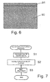
- a nickel-tungsten alloy plating layer 91 is formed on the surface of a stainless steel matrix material 90 of the disk rotor 22. It is desirable that the thickness of this nickel-tungsten alloy layer 91 be in the range of from approximately 0.5 ⁇ m to approximately 100 ⁇ m.
- Such a thickness range prevents excessive plating costs of a thick layer and peeling off as a result of frictional forces on a thin layer.
- the composition of the nickel-tungsten alloy plating There are no particular restrictions on the composition of the nickel-tungsten alloy plating. However, an additional effect can be expected if the proportion of tungsten in the plating is 20 wt % to 80 wt %. Accordingly, such a composition is desirable.
- the nickel-tungsten alloy layer 91 which may form the outermost surface, is subject to a heat treatment at 400°C to 700°C.
- a heat treatment improves the frictional force at high temperatures. It is surmised that the probable reason for this is that the effect of the nickel-tungsten alloy plating in increasing the frictional force at high temperatures is enhanced by this heat treatment.
- An even more superior effect on the braking force at high temperatures is shown if a heat treatment is performed in the temperature region of 450°C to 650°C, preferably 500°C to 600°C.
- the heat treatment step may be performed during or after the formation of the nickel-tungsten alloy layer on the pressing contact surfaces (friction surfaces) of the braking device.
- the heat treatment method that is used may be a method in which heating is accomplished using a vacuum furnace, atmospheric furnace, gas furnace, salt bath furnace, high-frequency heating apparatus or a combination of these means. There are no restrictions on the heating rate, uniform temperature maintenance time or cooling rate.
- Fig. 7 is a flow chart illustrating the manufacturing process for the disk rotor 22 shown in Fig. 6.
- the matrix material 90 which is formed into the shape of the disk rotor 22 is prepared in a step S1 by (for example) stamping a plate-shaped material made of a stainless steel alloy.
- nickel-tungsten alloy plating is performed on the prepared matrix material 90 in a step S2 so that a nickel-tungsten alloy plating layer 91 is formed.
- the surface of the nickel-tungsten alloy layer 91 is subjected to a heat treatment at 400°C to 700°C in a step S3 by means of an appropriate heating apparatus.
- nickel-tungsten alloy layer 91 was formed on the surface of the matrix material 90 of the disk rotor 22.
- a nickel-type plating layer 92 on the surface of the matrix material 90, and to form a nickel-tungsten alloy layer 91 on the surface of this nickel type layer 92 as shown in Fig. 8.
- the insertion of a relatively soft nickel-type layer 92 between the matrix material 90 and the nickel-tungsten alloy layer 91 produces a gradient effect in which the hardness gradually increases. Accordingly, the stress of the nickel-tungsten alloy layer itself can be dispersed so that the durability against peeling can be improved.
- the nickel-type layer may consist of Ni alone, or may be an alloy of Ni with P, Sn or the like.
- Fig. 9 is a flow chart illustrating the manufacturing process for the disk rotor 22 shown in Fig. 8. The process is the same as that shown in Fig. 7 for the first embodiment, except a nickel-type plating treatment is added in step S12 following the preparatory step S1 shown in Fig. 7.
- Fig. 10 is a cross-sectional view of another embodiment of a braking member such as disk rotor 22.
- a braking member such as disk rotor 22.
- the copper-type layer 93 may comprise Cu alone, or may be an alloy layer constructed from Cu with one or more metals selected from a group consisting of Zn, Sn and Ni.
- controllability refers to the ease of controlling the braking device during deceleration or stopping, and it refers in particular to the ease of control when the disk braking device 12 is operated by a human being. It is surmised that the probable reason for this is that the copper-type layer 93 produces an enhanced feedback effect so that minute transmitted information such as slight vibrations from the braking surfaces (friction surfaces) is increased, thus creating an effect that facilitates stronger feedback with respect to human sensory functions.
- Fig. 11 is a flow chart illustrating the manufacturing process for the disk rotor 22 shown in Fig. 10. The process is the same as that shown in Fig. 7 for the first embodiment, except a copper-type plating treatment is added in a step S22 following the preparation step S1 shown in Fig. 7.
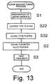
- Fig. 12 is a cross-sectional view of another embodiment of a braking member such as disk rotor 22. As shown in Fig. 12, it would also be possible to form a nickel-type plating layer 92 on the surface of the copper-type layer 93, and to form a nickel-tungsten alloy layer 91 on the surface of this nickel-type layer 92. This produces a hardness gradient in addition to increased controllability.
- the manufacturing process for this embodiment is shown in Fig. 13.
- step S32 a nickel-type plating treatment is added in step S32 following the copper-type plating treatment of step S22 in the manufacturing process shown in Fig. 11.
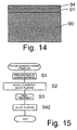
- Fig. 14 is a cross-sectional view of another embodiment of a braking member such as disk rotor 22.
- a further layer 94 may be formed on the surface of the nickel-tungsten alloy layer 91.
- Layer 94 may be constructed from one or more metals (an alloy) selected from a group consisting of Sn, Cu, Zn, Ni, Ag, Fe, Al, P, Mn, Bi and Cr.
- an alloy selected from a group consisting of Sn, Cu, Zn, Ni, Ag, Fe, Al, P, Mn, Bi and Cr.
- fine particles of carbides, oxides, nitrides or the like may be included in the nickel-tungsten alloy layer and/or the further layer in order to improve the frictional wear characteristics.
- a nickel-tungsten alloy plating is a plating with a strong tensile stress. Accordingly, countless cracks are formed in the plating surface of the surface layer part as a result of the difference in stress between this plating and the matrix material. When this plating is covered from above with a further layer that has a high covering effect, these cracks are repaired so that there is an effect that improves the water resistance and water-repellent properties on the microscopic level.
- Fig. 15 is a flow chart illustrating a manufacturing process for the braking member shown in Fig. 14. The process is the same as the process described in Fig. 7, except further plating treatment is added in a step S42 following the heat treatment process of step S3. Of course, a further plating treatment may be added following the heat treatment process of step S3 in the embodiments shown in Figs. 9, 11 and 13.
- the present inventors prepared various types of disk rotors with the test numbers described below, and the following four types of tests were performed on each rotor: 1) a steep slope braking test; 2) a wet braking test; 3) a corrosion resistance test; and 4) a controllability test.
- a bicycle having a commercially marketed disk braking device was used in the tests.
- the disk rotors were disk-shaped rotors made of an SUS410 stainless steel alloy. The rotors had a diameter of 200 mm and a thickness of 2 mm.
- the disk rotors with test numbers 1 through 14 were examples of disk rotors constructed according to the teachings of the present invention in which a nickel-tungsten alloy layer was formed, and disk rotors with test numbers 15 through 19 were comparative examples that had no plating layer or no nickel-tungsten alloy plating layer.
- Commercially marketed brake pads consisting of a copper-type sinter were used as the brake pads. The heat treatment was performed for 30 minutes at 500°C using a vacuum furnace following the formation of the nickel-tungsten alloy plating layer and prior to the formation of any further Sn-Ni alloy layer.
- the "first layer” refers to the layer directly above the matrix material
- the "second layer”, “third layer” and “fourth layer” respectively refer to layers that are located successively closer to the friction surface.
- an Ni-W (nickel-tungsten) plating layer with a thickness of 10 ⁇ m consisting of approximately 45% Ni and approximately 55% W (wt % in all cases) was formed as one of the first through third layers.
- a Ni plating layer constituting a nickel-type plating layer was formed to a thickness of 10 ⁇ m by an electroplating process in test numbers 3, 4, 7, 10, 11 and 14.
- an Sn-Ni plating layer constituting the further alloy layer was formed to a thickness of 1 ⁇ m by a pyrophosphate bath process in test numbers 2, 4, 6, 7, 9, 11, 13 and 14.
- a Cu layer was formed to a thickness of approximately 5 ⁇ m by a sulfuric acid bath process in test numbers 5-7 and 12-14.
- the gradient in the running direction of the test course was set at approximately 10%.
- a distance of 1000 m was covered while braking was performed by means of the hand brake.
- the braking distance was calculated using the test method for dry conditions described in Japanese Industrial Standard (JIS) D 9201. The evaluation of the steep slope test was performed as follows:
- the corrosion resistance test was performed for a test time of 24 hours using the CASS test method described in JIS H 8502 (Plating Corrosion Resistance Test Methods), and the conditions of corrosion were evaluated by visual inspection.
- the evaluation of the corrosion resistance test was performed as follows:
- test numbers 8 through 14 which were examples of the present invention in which a heat treatment was performed, a superior braking force was maintained throughout the entire test course during abrupt braking in the steep slope braking test. Furthermore, in the braking test performed immediately afterward, the braking distance was less than 4 m, indicating that no fading occurred. The braking surfaces showed no discoloration caused by braking, so that the braking devices were also desirable in terms of external appearance, and showed superior braking characteristics.
- test numbers 15 and 16 which were comparative examples, braking sometimes became difficult in the latter half of the test course during steep-slope braking in the steep slope braking test.
- the braking distance was less than 6 m, so no conspicuous fading was seen.
- the braking surfaces showed a brown discoloration indicating oxidation caused by braking, so that the braking devices were inferior in terms of external appearance.
- test numbers 17 through 19 which also were comparative examples
- braking sometimes became difficult in the latter half of the test course during steep-slope braking in the steep slope braking test.
- the braking distance was 6 m or greater, so that fading was seen.
- the braking surfaces showed a brown discoloration indicating oxidation caused by braking, so that the braking devices were inferior in terms of external appearance.
- the braking distance was 6 m or greater but less than 8 m in the case of test numbers 1, 3, 5, 8, 10 and 12, which were examples of the present invention in which no alloy type plating layer was formed. These examples showed approximately the same level of performance as the comparative example of test number 15, which was used as a reference value. On the other hand, in the case of test numbers 2, 4, 6, 7, 9, 11, 13 and 14, which were examples of the present invention in which a further plating layer was formed on the surface, the braking distance was less than 6 m. Thus, these examples showed a wet braking performance surpassing that of the comparative example of test number 15, which was used as a reference value.
- test numbers 17 and 18, which were comparative examples the braking distance was 8 m or greater, so these comparative examples were greatly inferior to the examples of the present invention.
- the braking distance was 6 m or greater but less than 8 m, indicating that these examples were inferior to the examples in which an alloy type plating layer was formed.
- test numbers 2, 4, 6, 7, 9, 11, 13 or 14 which were examples in which a further plating layer was formed. These examples thus showed a superior corrosion resistance, and were also desirable in terms of external appearance.
- test numbers 1, 3, 5, 8, 10 and 12 which are examples of the present invention in which no alloy type plating layer was formed, the results obtained were more or less at the same level as those of test number 15, which was used as a reference value.
- the area ratio of corroded and discolored parts was 0.02% or less (rating number 9.8 described in JIS H 8502). Thus, almost no corroded or discolored parts were seen. It was found from this data that it is advisable to form a further plating layer on the surface in order to improve the corrosion resistance and wet braking performance.
- test riders evaluating the control performance as superior accounted for 80% or more of the total responses in the case of test numbers 5 through 7 and 12 through 14, which were examples in which a copper type plating layer was formed. Thus, it was found that these examples showed an extremely superior control performance. Furthermore, even in the case of test numbers 1 through 4 and 8 through 11, which were examples in which no copper type plating layer was formed, the test riders evaluating the control performance as superior accounted for 60% or more but less than 80% of the total responses. Thus, it was found that these examples showed a superior control performance. On the whole, a superior control performance was obtained in the examples of the present invention.
- the braking device of test number 16 was evaluated as superior by 40% or more but fewer than 60% of the test riders.
- This comparative example showed a level of performance comparable to that of test number 15 (used as a reference value), and was therefore found to have an ordinary level of controllability.
- the braking devices of test numbers 17 through 19, which were comparative examples, were evaluated as superior by fewer than 40% of the test riders. Furthermore, there were numerous comments indicating that these braking devices lacked a sense of touch and showed poor responsiveness. Accordingly, the controllability of these braking devices was judged to be poor. It was found from these results that the controllability is improved by forming a copper-type plating layer on the surface of the matrix material.
- the braking device of test number 1 in which a nickel-tungsten alloy plating layer was formed directly on the surface of the matrix material, the braking device of test number 3, in which a nickel-tungsten alloy plating layer was formed following the formation of a nickel type plating layer on the surface of the matrix material, and the braking device of test number 15, which was used as a conventional example, were mounted on respective bicycles, and a braking test was performed over a running distance of 200 km to test the peeling strength of the plating layers.
- the surface roughness showed almost no change in the braking device of test number 3. In the case of the braking device of test number 1, the surface roughness showed a slight change, and a slight indentation thought to indicate peeling of the plating was seen in some areas.
- the braking device of test number 15 circumferential wear scars were observed on the surface. It was confirmed from these results that durability is improved by including a nickel-type layer. Furthermore, the amount of wear on the brake pads was less in the bicycles mounting test numbers 1 and 3, which were examples of the present invention, than in the bicycles mounting test number 15. In this braking device, a nickel-tungsten alloy plating layer is formed on at least the friction surface of the first member or the friction surface of the second member. Accordingly, the braking force tends not to drop even under harsh conditions of 400°C to 700°C, where fading ordinarily occurs. Consequently, the braking device can show a superior braking force.
- the coefficient of friction ⁇ may be cited as a physical value that generally governs the braking force.
- This coefficient of friction ⁇ is reportedly proportional to the shear strength and inversely proportional to the hardness.
- the "hardness” refers to the hardness of the matrix material
- the “shear strength” refers to the shear strength of the surface layer that provides the interface.
- the hardness or shear strength tends to drop as the temperature rises, so that the coefficient of friction ⁇ usually tends to remain constant or to drop.
- the coefficient of friction ⁇ may rise as a result of a synergistic effect between the drop in the hardness of the matrix material and the increase or maintenance of a constant value of the shear strength at high temperatures.
- nickel-tungsten alloy plating it is a well-known property of nickel-tungsten alloy plating that the hardness of the plating rises when the temperature rises.
- the present invention focuses on the shear strength of the nickel-tungsten alloy plating itself, and/or the shear strength of products produced by oxidation reactions when this plating is subjected to high-temperature friction, rather than on the hardness. It is surmised that a nickel-tungsten alloy plating layer has some type of mechanism that results in an additional increase in the shear strength when the plating layer is at a high temperature or is once exposed to a high temperature.
- disk braking devices used in bicycles were indicated as examples of braking devices.
- the present invention can be applied to all types of braking devices that utilize a frictional force.
- the present invention can be applied to drum braking devices, roller braking devices, coaster braking devices, caliper braking devices, cantilever braking devices, band braking devices and the like.
- braking devices that brake the rim of the wheel, such as caliper braking devices, cantilever braking devices and the like, it is sufficient to form a nickel-tungsten alloy plating layer on the friction surfaces of either the rim or the shoes, or on the friction surfaces of both of these parts.
- band brakes and inside-spreading braking devices such as drum braking devices, roller brakes and the like, it is sufficient to form a nickel-tungsten alloy plating layer on the friction surfaces of either the brake drums or the brake bands or brake shoes that make frictional contact with the brake drums, or on the friction surfaces of both of these parts.
- the braking devices to which the invention of the present application is applied may also be braking devices used in two-wheeled vehicles other than bicycles, other vehicles such as automobiles, railroad cars and the like, and various types of machinery or the like.
- a nickel-tungsten alloy plating layer was formed on the friction surfaces of a first member (disk rotor) that moved in linkage with a moving body (front wheel).
- a nickel-tungsten alloy plating layer it would also be possible to form a nickel-tungsten alloy plating layer on the friction surfaces of the second member (brake pads), or on the friction surfaces of both of these members.
- the material of the disk rotor was a stainless steel alloy to promote corrosion resistance.
- the material of the disk rotor may be any metal selected from a group consisting of stainless steel alloys, iron (to reduce expense), aluminum alloys (reduced weight), magnesium alloys (reduced weight) and titanium alloys (reduced weight and corrosion resistance). Corrosion of a magnesium rotor may be inhibited using an additional protective layer.
- the disk rotor may also be made of a hard non-metallic material that possesses heat resistance, such as carbon, graphite or the like.
Applications Claiming Priority (2)
| Application Number | Priority Date | Filing Date | Title |
|---|---|---|---|
| JP2001215295A JP3654854B2 (ja) | 2001-07-16 | 2001-07-16 | 自転車用ディスクブレーキ装置及びそのディスクロータの製造方法 |
| JP2001215295 | 2001-07-16 |
Publications (2)
| Publication Number | Publication Date |
|---|---|
| EP1277983A1 EP1277983A1 (en) | 2003-01-22 |
| EP1277983B1 true EP1277983B1 (en) | 2005-12-14 |
Family
ID=19049965
Family Applications (1)
| Application Number | Title | Priority Date | Filing Date |
|---|---|---|---|
| EP02015644A Expired - Lifetime EP1277983B1 (en) | 2001-07-16 | 2002-07-16 | Brake device & method using Ni-W alloy plating |
Country Status (7)
| Country | Link |
|---|---|
| US (1) | US20030010585A1 (ja) |
| EP (1) | EP1277983B1 (ja) |
| JP (1) | JP3654854B2 (ja) |
| CN (1) | CN1279294C (ja) |
| AT (1) | ATE313028T1 (ja) |
| DE (1) | DE60207937T2 (ja) |
| TW (1) | TW590942B (ja) |
Families Citing this family (145)
| Publication number | Priority date | Publication date | Assignee | Title |
|---|---|---|---|---|
| JP2005030565A (ja) | 2003-07-11 | 2005-02-03 | Shimano Inc | 自転車用ディスクロータ |
| US20060037819A1 (en) * | 2004-08-19 | 2006-02-23 | Shimano, Inc. | Bicycle disk brake rotor with laminated components having differing thicknesses |
| DE102004062082A1 (de) * | 2004-12-23 | 2006-07-06 | Audi Ag | Bremsvorrichtung für ein Fahrzeug, insbesondere für ein Kraftfahrzeug |
| US7677366B2 (en) | 2005-03-03 | 2010-03-16 | Akebono Brake Industry Co., Ltd. | Disc brake caliper and manufacturing method of disc brake caliper |
| US7484600B2 (en) * | 2006-06-16 | 2009-02-03 | Shimano, Inc. | Bicycle disk brake caliper with a recursive cooling system |
| US20090084639A1 (en) * | 2007-10-01 | 2009-04-02 | James Colegrove | Bicycle brake system |
| TW201114920A (en) * | 2009-10-26 | 2011-05-01 | Pneutech Manufacture Co Ltd | Surface treatment process for rotor of pneumatic tool |
| DE102010013343A1 (de) * | 2010-03-30 | 2011-10-06 | Daimler Ag | Reibscheibe mit einer Verschleißschutzschicht und integrierter Verschleißindikation und Zusammensetzungen der Verschleißschutzschicht |
| US10520052B2 (en) | 2012-01-18 | 2019-12-31 | Shimano Inc. | Bicycle disc brake rotor |
| US8881873B2 (en) | 2012-01-18 | 2014-11-11 | Shimano Inc. | Bicycle disc brake rotor |
| US9580136B2 (en) | 2012-01-18 | 2017-02-28 | Shimano Inc. | Corrosion resistant bicycle disc brake rotor |
| US8910757B2 (en) * | 2012-07-25 | 2014-12-16 | Yuan-Hung WEN | Heat-dissipating device for hydraulic brake system |
| US9525524B2 (en) | 2013-05-31 | 2016-12-20 | At&T Intellectual Property I, L.P. | Remote distributed antenna system |
| US9999038B2 (en) | 2013-05-31 | 2018-06-12 | At&T Intellectual Property I, L.P. | Remote distributed antenna system |
| US8897697B1 (en) | 2013-11-06 | 2014-11-25 | At&T Intellectual Property I, Lp | Millimeter-wave surface-wave communications |
| CN103614753B (zh) * | 2013-11-22 | 2015-10-28 | 西峡龙成特种材料有限公司 | 一种连铸结晶器铜板镍钨合金电镀层热处理工艺 |
| US9768833B2 (en) | 2014-09-15 | 2017-09-19 | At&T Intellectual Property I, L.P. | Method and apparatus for sensing a condition in a transmission medium of electromagnetic waves |
| US10063280B2 (en) | 2014-09-17 | 2018-08-28 | At&T Intellectual Property I, L.P. | Monitoring and mitigating conditions in a communication network |
| US9615269B2 (en) | 2014-10-02 | 2017-04-04 | At&T Intellectual Property I, L.P. | Method and apparatus that provides fault tolerance in a communication network |
| US9685992B2 (en) | 2014-10-03 | 2017-06-20 | At&T Intellectual Property I, L.P. | Circuit panel network and methods thereof |
| US9503189B2 (en) | 2014-10-10 | 2016-11-22 | At&T Intellectual Property I, L.P. | Method and apparatus for arranging communication sessions in a communication system |
| US9762289B2 (en) | 2014-10-14 | 2017-09-12 | At&T Intellectual Property I, L.P. | Method and apparatus for transmitting or receiving signals in a transportation system |
| US9973299B2 (en) | 2014-10-14 | 2018-05-15 | At&T Intellectual Property I, L.P. | Method and apparatus for adjusting a mode of communication in a communication network |
| US9769020B2 (en) | 2014-10-21 | 2017-09-19 | At&T Intellectual Property I, L.P. | Method and apparatus for responding to events affecting communications in a communication network |
| US9653770B2 (en) | 2014-10-21 | 2017-05-16 | At&T Intellectual Property I, L.P. | Guided wave coupler, coupling module and methods for use therewith |
| US9577306B2 (en) | 2014-10-21 | 2017-02-21 | At&T Intellectual Property I, L.P. | Guided-wave transmission device and methods for use therewith |
| US9312919B1 (en) | 2014-10-21 | 2016-04-12 | At&T Intellectual Property I, Lp | Transmission device with impairment compensation and methods for use therewith |
| US9627768B2 (en) | 2014-10-21 | 2017-04-18 | At&T Intellectual Property I, L.P. | Guided-wave transmission device with non-fundamental mode propagation and methods for use therewith |
| US9780834B2 (en) | 2014-10-21 | 2017-10-03 | At&T Intellectual Property I, L.P. | Method and apparatus for transmitting electromagnetic waves |
| US9742462B2 (en) | 2014-12-04 | 2017-08-22 | At&T Intellectual Property I, L.P. | Transmission medium and communication interfaces and methods for use therewith |
| US9997819B2 (en) | 2015-06-09 | 2018-06-12 | At&T Intellectual Property I, L.P. | Transmission medium and method for facilitating propagation of electromagnetic waves via a core |
| US10009067B2 (en) | 2014-12-04 | 2018-06-26 | At&T Intellectual Property I, L.P. | Method and apparatus for configuring a communication interface |
| US10243784B2 (en) | 2014-11-20 | 2019-03-26 | At&T Intellectual Property I, L.P. | System for generating topology information and methods thereof |
| US9800327B2 (en) | 2014-11-20 | 2017-10-24 | At&T Intellectual Property I, L.P. | Apparatus for controlling operations of a communication device and methods thereof |
| US9461706B1 (en) | 2015-07-31 | 2016-10-04 | At&T Intellectual Property I, Lp | Method and apparatus for exchanging communication signals |
| US9954287B2 (en) | 2014-11-20 | 2018-04-24 | At&T Intellectual Property I, L.P. | Apparatus for converting wireless signals and electromagnetic waves and methods thereof |
| US10340573B2 (en) | 2016-10-26 | 2019-07-02 | At&T Intellectual Property I, L.P. | Launcher with cylindrical coupling device and methods for use therewith |
| US9544006B2 (en) | 2014-11-20 | 2017-01-10 | At&T Intellectual Property I, L.P. | Transmission device with mode division multiplexing and methods for use therewith |
| US9876570B2 (en) | 2015-02-20 | 2018-01-23 | At&T Intellectual Property I, Lp | Guided-wave transmission device with non-fundamental mode propagation and methods for use therewith |
| US9749013B2 (en) | 2015-03-17 | 2017-08-29 | At&T Intellectual Property I, L.P. | Method and apparatus for reducing attenuation of electromagnetic waves guided by a transmission medium |
| US9705561B2 (en) | 2015-04-24 | 2017-07-11 | At&T Intellectual Property I, L.P. | Directional coupling device and methods for use therewith |
| US10224981B2 (en) | 2015-04-24 | 2019-03-05 | At&T Intellectual Property I, Lp | Passive electrical coupling device and methods for use therewith |
| US9793954B2 (en) | 2015-04-28 | 2017-10-17 | At&T Intellectual Property I, L.P. | Magnetic coupling device and methods for use therewith |
| US9948354B2 (en) | 2015-04-28 | 2018-04-17 | At&T Intellectual Property I, L.P. | Magnetic coupling device with reflective plate and methods for use therewith |
| US9748626B2 (en) | 2015-05-14 | 2017-08-29 | At&T Intellectual Property I, L.P. | Plurality of cables having different cross-sectional shapes which are bundled together to form a transmission medium |
| US9871282B2 (en) | 2015-05-14 | 2018-01-16 | At&T Intellectual Property I, L.P. | At least one transmission medium having a dielectric surface that is covered at least in part by a second dielectric |
| US9490869B1 (en) | 2015-05-14 | 2016-11-08 | At&T Intellectual Property I, L.P. | Transmission medium having multiple cores and methods for use therewith |
| US10650940B2 (en) | 2015-05-15 | 2020-05-12 | At&T Intellectual Property I, L.P. | Transmission medium having a conductive material and methods for use therewith |
| US9917341B2 (en) | 2015-05-27 | 2018-03-13 | At&T Intellectual Property I, L.P. | Apparatus and method for launching electromagnetic waves and for modifying radial dimensions of the propagating electromagnetic waves |
| US10812174B2 (en) | 2015-06-03 | 2020-10-20 | At&T Intellectual Property I, L.P. | Client node device and methods for use therewith |
| US9866309B2 (en) | 2015-06-03 | 2018-01-09 | At&T Intellectual Property I, Lp | Host node device and methods for use therewith |
| US9912381B2 (en) | 2015-06-03 | 2018-03-06 | At&T Intellectual Property I, Lp | Network termination and methods for use therewith |
| US9913139B2 (en) | 2015-06-09 | 2018-03-06 | At&T Intellectual Property I, L.P. | Signal fingerprinting for authentication of communicating devices |
| US9608692B2 (en) | 2015-06-11 | 2017-03-28 | At&T Intellectual Property I, L.P. | Repeater and methods for use therewith |
| US9820146B2 (en) | 2015-06-12 | 2017-11-14 | At&T Intellectual Property I, L.P. | Method and apparatus for authentication and identity management of communicating devices |
| US9667317B2 (en) | 2015-06-15 | 2017-05-30 | At&T Intellectual Property I, L.P. | Method and apparatus for providing security using network traffic adjustments |
| US9640850B2 (en) | 2015-06-25 | 2017-05-02 | At&T Intellectual Property I, L.P. | Methods and apparatus for inducing a non-fundamental wave mode on a transmission medium |
| US9865911B2 (en) | 2015-06-25 | 2018-01-09 | At&T Intellectual Property I, L.P. | Waveguide system for slot radiating first electromagnetic waves that are combined into a non-fundamental wave mode second electromagnetic wave on a transmission medium |
| US9509415B1 (en) | 2015-06-25 | 2016-11-29 | At&T Intellectual Property I, L.P. | Methods and apparatus for inducing a fundamental wave mode on a transmission medium |
| US9853342B2 (en) | 2015-07-14 | 2017-12-26 | At&T Intellectual Property I, L.P. | Dielectric transmission medium connector and methods for use therewith |
| US9882257B2 (en) | 2015-07-14 | 2018-01-30 | At&T Intellectual Property I, L.P. | Method and apparatus for launching a wave mode that mitigates interference |
| US10320586B2 (en) | 2015-07-14 | 2019-06-11 | At&T Intellectual Property I, L.P. | Apparatus and methods for generating non-interfering electromagnetic waves on an insulated transmission medium |
| US10033108B2 (en) | 2015-07-14 | 2018-07-24 | At&T Intellectual Property I, L.P. | Apparatus and methods for generating an electromagnetic wave having a wave mode that mitigates interference |
| US10148016B2 (en) | 2015-07-14 | 2018-12-04 | At&T Intellectual Property I, L.P. | Apparatus and methods for communicating utilizing an antenna array |
| US9628116B2 (en) | 2015-07-14 | 2017-04-18 | At&T Intellectual Property I, L.P. | Apparatus and methods for transmitting wireless signals |
| US10341142B2 (en) | 2015-07-14 | 2019-07-02 | At&T Intellectual Property I, L.P. | Apparatus and methods for generating non-interfering electromagnetic waves on an uninsulated conductor |
| US10044409B2 (en) | 2015-07-14 | 2018-08-07 | At&T Intellectual Property I, L.P. | Transmission medium and methods for use therewith |
| US9847566B2 (en) | 2015-07-14 | 2017-12-19 | At&T Intellectual Property I, L.P. | Method and apparatus for adjusting a field of a signal to mitigate interference |
| US10170840B2 (en) | 2015-07-14 | 2019-01-01 | At&T Intellectual Property I, L.P. | Apparatus and methods for sending or receiving electromagnetic signals |
| US10205655B2 (en) | 2015-07-14 | 2019-02-12 | At&T Intellectual Property I, L.P. | Apparatus and methods for communicating utilizing an antenna array and multiple communication paths |
| US10090606B2 (en) | 2015-07-15 | 2018-10-02 | At&T Intellectual Property I, L.P. | Antenna system with dielectric array and methods for use therewith |
| US9793951B2 (en) | 2015-07-15 | 2017-10-17 | At&T Intellectual Property I, L.P. | Method and apparatus for launching a wave mode that mitigates interference |
| US9948333B2 (en) | 2015-07-23 | 2018-04-17 | At&T Intellectual Property I, L.P. | Method and apparatus for wireless communications to mitigate interference |
| US9871283B2 (en) | 2015-07-23 | 2018-01-16 | At&T Intellectual Property I, Lp | Transmission medium having a dielectric core comprised of plural members connected by a ball and socket configuration |
| US9749053B2 (en) | 2015-07-23 | 2017-08-29 | At&T Intellectual Property I, L.P. | Node device, repeater and methods for use therewith |
| US9912027B2 (en) | 2015-07-23 | 2018-03-06 | At&T Intellectual Property I, L.P. | Method and apparatus for exchanging communication signals |
| US9967173B2 (en) | 2015-07-31 | 2018-05-08 | At&T Intellectual Property I, L.P. | Method and apparatus for authentication and identity management of communicating devices |
| US9735833B2 (en) | 2015-07-31 | 2017-08-15 | At&T Intellectual Property I, L.P. | Method and apparatus for communications management in a neighborhood network |
| US9904535B2 (en) | 2015-09-14 | 2018-02-27 | At&T Intellectual Property I, L.P. | Method and apparatus for distributing software |
| US9769128B2 (en) | 2015-09-28 | 2017-09-19 | At&T Intellectual Property I, L.P. | Method and apparatus for encryption of communications over a network |
| US9729197B2 (en) | 2015-10-01 | 2017-08-08 | At&T Intellectual Property I, L.P. | Method and apparatus for communicating network management traffic over a network |
| US9876264B2 (en) | 2015-10-02 | 2018-01-23 | At&T Intellectual Property I, Lp | Communication system, guided wave switch and methods for use therewith |
| US10355367B2 (en) | 2015-10-16 | 2019-07-16 | At&T Intellectual Property I, L.P. | Antenna structure for exchanging wireless signals |
| US10352382B2 (en) * | 2016-07-27 | 2019-07-16 | Shimano Inc. | Bicycle disc brake rotor |
| US9860075B1 (en) | 2016-08-26 | 2018-01-02 | At&T Intellectual Property I, L.P. | Method and communication node for broadband distribution |
| US10291311B2 (en) | 2016-09-09 | 2019-05-14 | At&T Intellectual Property I, L.P. | Method and apparatus for mitigating a fault in a distributed antenna system |
| US11032819B2 (en) | 2016-09-15 | 2021-06-08 | At&T Intellectual Property I, L.P. | Method and apparatus for use with a radio distributed antenna system having a control channel reference signal |
| US10135147B2 (en) | 2016-10-18 | 2018-11-20 | At&T Intellectual Property I, L.P. | Apparatus and methods for launching guided waves via an antenna |
| US10340600B2 (en) | 2016-10-18 | 2019-07-02 | At&T Intellectual Property I, L.P. | Apparatus and methods for launching guided waves via plural waveguide systems |
| US10135146B2 (en) | 2016-10-18 | 2018-11-20 | At&T Intellectual Property I, L.P. | Apparatus and methods for launching guided waves via circuits |
| US9991580B2 (en) | 2016-10-21 | 2018-06-05 | At&T Intellectual Property I, L.P. | Launcher and coupling system for guided wave mode cancellation |
| US10811767B2 (en) | 2016-10-21 | 2020-10-20 | At&T Intellectual Property I, L.P. | System and dielectric antenna with convex dielectric radome |
| US9876605B1 (en) | 2016-10-21 | 2018-01-23 | At&T Intellectual Property I, L.P. | Launcher and coupling system to support desired guided wave mode |
| US10374316B2 (en) | 2016-10-21 | 2019-08-06 | At&T Intellectual Property I, L.P. | System and dielectric antenna with non-uniform dielectric |
| US10312567B2 (en) | 2016-10-26 | 2019-06-04 | At&T Intellectual Property I, L.P. | Launcher with planar strip antenna and methods for use therewith |
| US10224634B2 (en) | 2016-11-03 | 2019-03-05 | At&T Intellectual Property I, L.P. | Methods and apparatus for adjusting an operational characteristic of an antenna |
| US10291334B2 (en) | 2016-11-03 | 2019-05-14 | At&T Intellectual Property I, L.P. | System for detecting a fault in a communication system |
| US10498044B2 (en) | 2016-11-03 | 2019-12-03 | At&T Intellectual Property I, L.P. | Apparatus for configuring a surface of an antenna |
| US10225025B2 (en) | 2016-11-03 | 2019-03-05 | At&T Intellectual Property I, L.P. | Method and apparatus for detecting a fault in a communication system |
| US10090594B2 (en) | 2016-11-23 | 2018-10-02 | At&T Intellectual Property I, L.P. | Antenna system having structural configurations for assembly |
| US10178445B2 (en) | 2016-11-23 | 2019-01-08 | At&T Intellectual Property I, L.P. | Methods, devices, and systems for load balancing between a plurality of waveguides |
| US10340603B2 (en) | 2016-11-23 | 2019-07-02 | At&T Intellectual Property I, L.P. | Antenna system having shielded structural configurations for assembly |
| US10340601B2 (en) | 2016-11-23 | 2019-07-02 | At&T Intellectual Property I, L.P. | Multi-antenna system and methods for use therewith |
| US10535928B2 (en) | 2016-11-23 | 2020-01-14 | At&T Intellectual Property I, L.P. | Antenna system and methods for use therewith |
| US10361489B2 (en) | 2016-12-01 | 2019-07-23 | At&T Intellectual Property I, L.P. | Dielectric dish antenna system and methods for use therewith |
| US10305190B2 (en) | 2016-12-01 | 2019-05-28 | At&T Intellectual Property I, L.P. | Reflecting dielectric antenna system and methods for use therewith |
| US9927517B1 (en) | 2016-12-06 | 2018-03-27 | At&T Intellectual Property I, L.P. | Apparatus and methods for sensing rainfall |
| US10755542B2 (en) | 2016-12-06 | 2020-08-25 | At&T Intellectual Property I, L.P. | Method and apparatus for surveillance via guided wave communication |
| US10020844B2 (en) | 2016-12-06 | 2018-07-10 | T&T Intellectual Property I, L.P. | Method and apparatus for broadcast communication via guided waves |
| US10694379B2 (en) | 2016-12-06 | 2020-06-23 | At&T Intellectual Property I, L.P. | Waveguide system with device-based authentication and methods for use therewith |
| US10382976B2 (en) | 2016-12-06 | 2019-08-13 | At&T Intellectual Property I, L.P. | Method and apparatus for managing wireless communications based on communication paths and network device positions |
| US10135145B2 (en) | 2016-12-06 | 2018-11-20 | At&T Intellectual Property I, L.P. | Apparatus and methods for generating an electromagnetic wave along a transmission medium |
| US10727599B2 (en) | 2016-12-06 | 2020-07-28 | At&T Intellectual Property I, L.P. | Launcher with slot antenna and methods for use therewith |
| US10439675B2 (en) | 2016-12-06 | 2019-10-08 | At&T Intellectual Property I, L.P. | Method and apparatus for repeating guided wave communication signals |
| US10637149B2 (en) | 2016-12-06 | 2020-04-28 | At&T Intellectual Property I, L.P. | Injection molded dielectric antenna and methods for use therewith |
| US10819035B2 (en) | 2016-12-06 | 2020-10-27 | At&T Intellectual Property I, L.P. | Launcher with helical antenna and methods for use therewith |
| US10326494B2 (en) | 2016-12-06 | 2019-06-18 | At&T Intellectual Property I, L.P. | Apparatus for measurement de-embedding and methods for use therewith |
| US10243270B2 (en) | 2016-12-07 | 2019-03-26 | At&T Intellectual Property I, L.P. | Beam adaptive multi-feed dielectric antenna system and methods for use therewith |
| US10446936B2 (en) | 2016-12-07 | 2019-10-15 | At&T Intellectual Property I, L.P. | Multi-feed dielectric antenna system and methods for use therewith |
| KR102429006B1 (ko) * | 2016-12-07 | 2022-08-03 | 현대자동차 주식회사 | 브레이크 디스크를 갖는 허브유닛 |
| US10547348B2 (en) | 2016-12-07 | 2020-01-28 | At&T Intellectual Property I, L.P. | Method and apparatus for switching transmission mediums in a communication system |
| US10389029B2 (en) | 2016-12-07 | 2019-08-20 | At&T Intellectual Property I, L.P. | Multi-feed dielectric antenna system with core selection and methods for use therewith |
| US10168695B2 (en) | 2016-12-07 | 2019-01-01 | At&T Intellectual Property I, L.P. | Method and apparatus for controlling an unmanned aircraft |
| US10027397B2 (en) | 2016-12-07 | 2018-07-17 | At&T Intellectual Property I, L.P. | Distributed antenna system and methods for use therewith |
| US10139820B2 (en) | 2016-12-07 | 2018-11-27 | At&T Intellectual Property I, L.P. | Method and apparatus for deploying equipment of a communication system |
| US9893795B1 (en) | 2016-12-07 | 2018-02-13 | At&T Intellectual Property I, Lp | Method and repeater for broadband distribution |
| US10359749B2 (en) | 2016-12-07 | 2019-07-23 | At&T Intellectual Property I, L.P. | Method and apparatus for utilities management via guided wave communication |
| US9911020B1 (en) | 2016-12-08 | 2018-03-06 | At&T Intellectual Property I, L.P. | Method and apparatus for tracking via a radio frequency identification device |
| US10411356B2 (en) | 2016-12-08 | 2019-09-10 | At&T Intellectual Property I, L.P. | Apparatus and methods for selectively targeting communication devices with an antenna array |
| US10069535B2 (en) | 2016-12-08 | 2018-09-04 | At&T Intellectual Property I, L.P. | Apparatus and methods for launching electromagnetic waves having a certain electric field structure |
| US10530505B2 (en) | 2016-12-08 | 2020-01-07 | At&T Intellectual Property I, L.P. | Apparatus and methods for launching electromagnetic waves along a transmission medium |
| US10916969B2 (en) | 2016-12-08 | 2021-02-09 | At&T Intellectual Property I, L.P. | Method and apparatus for providing power using an inductive coupling |
| US10326689B2 (en) | 2016-12-08 | 2019-06-18 | At&T Intellectual Property I, L.P. | Method and system for providing alternative communication paths |
| US10777873B2 (en) | 2016-12-08 | 2020-09-15 | At&T Intellectual Property I, L.P. | Method and apparatus for mounting network devices |
| US10601494B2 (en) | 2016-12-08 | 2020-03-24 | At&T Intellectual Property I, L.P. | Dual-band communication device and method for use therewith |
| US10103422B2 (en) | 2016-12-08 | 2018-10-16 | At&T Intellectual Property I, L.P. | Method and apparatus for mounting network devices |
| US9998870B1 (en) | 2016-12-08 | 2018-06-12 | At&T Intellectual Property I, L.P. | Method and apparatus for proximity sensing |
| US10938108B2 (en) | 2016-12-08 | 2021-03-02 | At&T Intellectual Property I, L.P. | Frequency selective multi-feed dielectric antenna system and methods for use therewith |
| US10389037B2 (en) | 2016-12-08 | 2019-08-20 | At&T Intellectual Property I, L.P. | Apparatus and methods for selecting sections of an antenna array and use therewith |
| US9838896B1 (en) | 2016-12-09 | 2017-12-05 | At&T Intellectual Property I, L.P. | Method and apparatus for assessing network coverage |
| US10340983B2 (en) | 2016-12-09 | 2019-07-02 | At&T Intellectual Property I, L.P. | Method and apparatus for surveying remote sites via guided wave communications |
| US10264586B2 (en) | 2016-12-09 | 2019-04-16 | At&T Mobility Ii Llc | Cloud-based packet controller and methods for use therewith |
| US9973940B1 (en) | 2017-02-27 | 2018-05-15 | At&T Intellectual Property I, L.P. | Apparatus and methods for dynamic impedance matching of a guided wave launcher |
| US10298293B2 (en) | 2017-03-13 | 2019-05-21 | At&T Intellectual Property I, L.P. | Apparatus of communication utilizing wireless network devices |
| JP6841748B2 (ja) * | 2017-10-31 | 2021-03-10 | 株式会社シマノ | 制御装置およびブレーキシステム |
Family Cites Families (14)
| Publication number | Priority date | Publication date | Assignee | Title |
|---|---|---|---|---|
| GB554540A (en) * | 1941-01-29 | 1943-07-08 | Gen Motors Corp | Improvements in and relating to composite friction articles |
| US4136230A (en) * | 1976-07-29 | 1979-01-23 | Eutectic Corporation | Wear resistant alloy coating containing tungsten carbide |
| JPS53113876A (en) * | 1977-03-15 | 1978-10-04 | Daido Metal Co Ltd | Metallbacked slideerequired member |
| DE3033139A1 (de) * | 1980-09-03 | 1982-04-08 | Alfred Teves Gmbh, 6000 Frankfurt | Vorrichtung mit einer reibpaarung, insbesondere reibungsbremse oder reibungskupplung |
| DE3225552C2 (de) * | 1982-07-08 | 1985-02-14 | Oexle, Friedrich, 7000 Stuttgart | Gleit- oder Bremsbelag |
| JP2508712B2 (ja) * | 1986-05-27 | 1996-06-19 | ブリヂストンサイクル株式会社 | 自転車用リム |
| FR2678334B1 (fr) * | 1991-06-28 | 1997-04-30 | Carbone Ind | Dispositif de plaquette de frein a disque en particulier a garniture en carbone-carbone. |
| CA2099397A1 (en) * | 1992-07-07 | 1994-01-08 | Gerald S. Cole | Composite disk brake rotor and method of making |
| US5927865A (en) * | 1996-08-28 | 1999-07-27 | Nsk Ltd. | Rolling apparatus |
| US5964322A (en) * | 1997-11-06 | 1999-10-12 | Otis Elevator Company | Elevator safety brake having a plasma sprayed friction coating |
| JPH11223230A (ja) * | 1998-02-04 | 1999-08-17 | Yuusan Gasket Kk | ディスクブレーキの鳴き防止用シムおよびディスクブレーキ |
| JP2000179616A (ja) * | 1998-12-11 | 2000-06-27 | Daido Metal Co Ltd | 摺動部材 |
| JP2001165210A (ja) * | 1999-12-14 | 2001-06-19 | Nisshinbo Ind Inc | ディスクブレーキ、ディスクブレーキパッド、及び該ディスクブレーキパッド用バックプレート |
| US6340074B1 (en) * | 2000-04-06 | 2002-01-22 | Avid Llc | Pad wear compensator for a disc brake caliper |
-
2001
- 2001-07-16 JP JP2001215295A patent/JP3654854B2/ja not_active Expired - Fee Related
-
2002
- 2002-07-15 CN CN02126205.5A patent/CN1279294C/zh not_active Expired - Fee Related
- 2002-07-15 TW TW091115715A patent/TW590942B/zh not_active IP Right Cessation
- 2002-07-15 US US10/196,084 patent/US20030010585A1/en not_active Abandoned
- 2002-07-16 AT AT02015644T patent/ATE313028T1/de not_active IP Right Cessation
- 2002-07-16 DE DE60207937T patent/DE60207937T2/de not_active Expired - Lifetime
- 2002-07-16 EP EP02015644A patent/EP1277983B1/en not_active Expired - Lifetime
Also Published As
| Publication number | Publication date |
|---|---|
| EP1277983A1 (en) | 2003-01-22 |
| TW590942B (en) | 2004-06-11 |
| ATE313028T1 (de) | 2005-12-15 |
| US20030010585A1 (en) | 2003-01-16 |
| DE60207937D1 (de) | 2006-01-19 |
| JP3654854B2 (ja) | 2005-06-02 |
| JP2003028219A (ja) | 2003-01-29 |
| DE60207937T2 (de) | 2006-06-14 |
| CN1397468A (zh) | 2003-02-19 |
| CN1279294C (zh) | 2006-10-11 |
Similar Documents
| Publication | Publication Date | Title |
|---|---|---|
| EP1277983B1 (en) | Brake device & method using Ni-W alloy plating | |
| US7424938B2 (en) | Bicycle disc brake rotor | |
| EP1770301B1 (en) | Bicycle disc brake pad | |
| EP1975450B1 (en) | Bicycle disk brake pad | |
| US4049090A (en) | Brake discs | |
| JP2004513311A (ja) | ブレーキディスクおよび該ブレーキディスクを製造するための方法 | |
| JP2005030565A (ja) | 自転車用ディスクロータ | |
| US20070144839A1 (en) | Integrated brake, suspension and wheel system | |
| TWI547407B (zh) | 自行車盤式制動器轉子 | |
| FR2888297A1 (fr) | Disque de frein composite et procede de fabrication | |
| US4342380A (en) | Light weight disc brake caliper | |
| EP1842767B1 (en) | Bicycle disk brake pad with titanium backing plate | |
| EP3971440B1 (en) | Braking band of a disc brake disc and disc brake disc | |
| JPS60230961A (ja) | デイスクブレ−キ用デイスク材料 | |
| JPS6358296B2 (ja) | ||
| KR20220147111A (ko) | 브레이크 디스크 및 그 제조 방법 | |
| JP4676220B2 (ja) | ディスクブレーキ用キャリパ | |
| KR100825369B1 (ko) | 디스크 브레이크 로우터 | |
| GB2146554A (en) | An aluminium brake component provided with a wearing surface | |
| US20010023725A1 (en) | Brake disk for motor vehicles, as well as a steel alloy and a method for producing them | |
| JP4533475B2 (ja) | ディスクブレーキ用ロータ | |
| JPH0942339A (ja) | 複合金属層からなるブレーキディスク | |
| KR20030075972A (ko) | 브레이크 저더를 최소화한 브레이크 로터 및 제조방법 | |
| JPH06257631A (ja) | 断熱性摩擦部品および断熱性油圧ピストン |
Legal Events
| Date | Code | Title | Description |
|---|---|---|---|
| PUAI | Public reference made under article 153(3) epc to a published international application that has entered the european phase |
Free format text: ORIGINAL CODE: 0009012 |
|
| AK | Designated contracting states |
Kind code of ref document: A1 Designated state(s): AT BE BG CH CY CZ DE DK EE ES FI FR GB GR IE IT LI LU MC NL PT SE SK TR |
|
| AX | Request for extension of the european patent |
Free format text: AL;LT;LV;MK;RO;SI |
|
| 17P | Request for examination filed |
Effective date: 20021220 |
|
| AKX | Designation fees paid |
Designated state(s): AT BE BG CH CY CZ DE DK EE ES FI FR GB GR IE IT LI LU MC NL PT SE SK TR |
|
| 17Q | First examination report despatched |
Effective date: 20041203 |
|
| GRAP | Despatch of communication of intention to grant a patent |
Free format text: ORIGINAL CODE: EPIDOSNIGR1 |
|
| GRAS | Grant fee paid |
Free format text: ORIGINAL CODE: EPIDOSNIGR3 |
|
| GRAA | (expected) grant |
Free format text: ORIGINAL CODE: 0009210 |
|
| AK | Designated contracting states |
Kind code of ref document: B1 Designated state(s): AT BE BG CH CY CZ DE DK EE ES FI FR GB GR IE IT LI LU MC NL PT SE SK TR |
|
| PG25 | Lapsed in a contracting state [announced via postgrant information from national office to epo] |
Ref country code: AT Free format text: LAPSE BECAUSE OF FAILURE TO SUBMIT A TRANSLATION OF THE DESCRIPTION OR TO PAY THE FEE WITHIN THE PRESCRIBED TIME-LIMIT Effective date: 20051214 Ref country code: LI Free format text: LAPSE BECAUSE OF FAILURE TO SUBMIT A TRANSLATION OF THE DESCRIPTION OR TO PAY THE FEE WITHIN THE PRESCRIBED TIME-LIMIT Effective date: 20051214 Ref country code: CH Free format text: LAPSE BECAUSE OF FAILURE TO SUBMIT A TRANSLATION OF THE DESCRIPTION OR TO PAY THE FEE WITHIN THE PRESCRIBED TIME-LIMIT Effective date: 20051214 Ref country code: FI Free format text: LAPSE BECAUSE OF FAILURE TO SUBMIT A TRANSLATION OF THE DESCRIPTION OR TO PAY THE FEE WITHIN THE PRESCRIBED TIME-LIMIT Effective date: 20051214 Ref country code: BE Free format text: LAPSE BECAUSE OF FAILURE TO SUBMIT A TRANSLATION OF THE DESCRIPTION OR TO PAY THE FEE WITHIN THE PRESCRIBED TIME-LIMIT Effective date: 20051214 Ref country code: SK Free format text: LAPSE BECAUSE OF FAILURE TO SUBMIT A TRANSLATION OF THE DESCRIPTION OR TO PAY THE FEE WITHIN THE PRESCRIBED TIME-LIMIT Effective date: 20051214 |
|
| REG | Reference to a national code |
Ref country code: GB Ref legal event code: FG4D |
|
| REG | Reference to a national code |
Ref country code: CH Ref legal event code: EP |
|
| REG | Reference to a national code |
Ref country code: IE Ref legal event code: FG4D |
|
| REF | Corresponds to: |
Ref document number: 60207937 Country of ref document: DE Date of ref document: 20060119 Kind code of ref document: P |
|
| PG25 | Lapsed in a contracting state [announced via postgrant information from national office to epo] |
Ref country code: DK Free format text: LAPSE BECAUSE OF FAILURE TO SUBMIT A TRANSLATION OF THE DESCRIPTION OR TO PAY THE FEE WITHIN THE PRESCRIBED TIME-LIMIT Effective date: 20060314 Ref country code: BG Free format text: LAPSE BECAUSE OF FAILURE TO SUBMIT A TRANSLATION OF THE DESCRIPTION OR TO PAY THE FEE WITHIN THE PRESCRIBED TIME-LIMIT Effective date: 20060314 Ref country code: GR Free format text: LAPSE BECAUSE OF FAILURE TO SUBMIT A TRANSLATION OF THE DESCRIPTION OR TO PAY THE FEE WITHIN THE PRESCRIBED TIME-LIMIT Effective date: 20060314 Ref country code: SE Free format text: LAPSE BECAUSE OF FAILURE TO SUBMIT A TRANSLATION OF THE DESCRIPTION OR TO PAY THE FEE WITHIN THE PRESCRIBED TIME-LIMIT Effective date: 20060314 |
|
| PG25 | Lapsed in a contracting state [announced via postgrant information from national office to epo] |
Ref country code: ES Free format text: LAPSE BECAUSE OF FAILURE TO SUBMIT A TRANSLATION OF THE DESCRIPTION OR TO PAY THE FEE WITHIN THE PRESCRIBED TIME-LIMIT Effective date: 20060325 |
|
| PG25 | Lapsed in a contracting state [announced via postgrant information from national office to epo] |
Ref country code: PT Free format text: LAPSE BECAUSE OF FAILURE TO SUBMIT A TRANSLATION OF THE DESCRIPTION OR TO PAY THE FEE WITHIN THE PRESCRIBED TIME-LIMIT Effective date: 20060515 |
|
| REG | Reference to a national code |
Ref country code: CH Ref legal event code: PL |
|
| PG25 | Lapsed in a contracting state [announced via postgrant information from national office to epo] |
Ref country code: GB Free format text: LAPSE BECAUSE OF NON-PAYMENT OF DUE FEES Effective date: 20060716 |
|
| PG25 | Lapsed in a contracting state [announced via postgrant information from national office to epo] |
Ref country code: IE Free format text: LAPSE BECAUSE OF NON-PAYMENT OF DUE FEES Effective date: 20060717 |
|
| PGFP | Annual fee paid to national office [announced via postgrant information from national office to epo] |
Ref country code: NL Payment date: 20060718 Year of fee payment: 5 |
|
| PG25 | Lapsed in a contracting state [announced via postgrant information from national office to epo] |
Ref country code: MC Free format text: LAPSE BECAUSE OF NON-PAYMENT OF DUE FEES Effective date: 20060731 |
|
| RAP2 | Party data changed (patent owner data changed or rights of a patent transferred) |
Owner name: SHIMANO INC. |
|
| ET | Fr: translation filed | ||
| NLT2 | Nl: modifications (of names), taken from the european patent patent bulletin |
Owner name: SHIMANO INC. Effective date: 20060802 |
|
| PLBE | No opposition filed within time limit |
Free format text: ORIGINAL CODE: 0009261 |
|
| STAA | Information on the status of an ep patent application or granted ep patent |
Free format text: STATUS: NO OPPOSITION FILED WITHIN TIME LIMIT |
|
| 26N | No opposition filed |
Effective date: 20060915 |
|
| GBPC | Gb: european patent ceased through non-payment of renewal fee |
Effective date: 20060716 |
|
| REG | Reference to a national code |
Ref country code: IE Ref legal event code: MM4A |
|
| NLV4 | Nl: lapsed or anulled due to non-payment of the annual fee |
Effective date: 20080201 |
|
| PG25 | Lapsed in a contracting state [announced via postgrant information from national office to epo] |
Ref country code: NL Free format text: LAPSE BECAUSE OF NON-PAYMENT OF DUE FEES Effective date: 20080201 |
|
| PGFP | Annual fee paid to national office [announced via postgrant information from national office to epo] |
Ref country code: CZ Payment date: 20060629 Year of fee payment: 5 |
|
| PG25 | Lapsed in a contracting state [announced via postgrant information from national office to epo] |
Ref country code: CZ Free format text: LAPSE BECAUSE OF NON-PAYMENT OF DUE FEES Effective date: 20070716 |
|
| PG25 | Lapsed in a contracting state [announced via postgrant information from national office to epo] |
Ref country code: EE Free format text: LAPSE BECAUSE OF FAILURE TO SUBMIT A TRANSLATION OF THE DESCRIPTION OR TO PAY THE FEE WITHIN THE PRESCRIBED TIME-LIMIT Effective date: 20051214 |
|
| PG25 | Lapsed in a contracting state [announced via postgrant information from national office to epo] |
Ref country code: LU Free format text: LAPSE BECAUSE OF NON-PAYMENT OF DUE FEES Effective date: 20060716 Ref country code: TR Free format text: LAPSE BECAUSE OF FAILURE TO SUBMIT A TRANSLATION OF THE DESCRIPTION OR TO PAY THE FEE WITHIN THE PRESCRIBED TIME-LIMIT Effective date: 20051214 |
|
| PG25 | Lapsed in a contracting state [announced via postgrant information from national office to epo] |
Ref country code: CY Free format text: LAPSE BECAUSE OF FAILURE TO SUBMIT A TRANSLATION OF THE DESCRIPTION OR TO PAY THE FEE WITHIN THE PRESCRIBED TIME-LIMIT Effective date: 20051214 |
|
| PGFP | Annual fee paid to national office [announced via postgrant information from national office to epo] |
Ref country code: FR Payment date: 20140708 Year of fee payment: 13 |
|
| PGFP | Annual fee paid to national office [announced via postgrant information from national office to epo] |
Ref country code: IT Payment date: 20140716 Year of fee payment: 13 |
|
| PG25 | Lapsed in a contracting state [announced via postgrant information from national office to epo] |
Ref country code: IT Free format text: LAPSE BECAUSE OF NON-PAYMENT OF DUE FEES Effective date: 20150716 |
|
| REG | Reference to a national code |
Ref country code: FR Ref legal event code: ST Effective date: 20160331 |
|
| PG25 | Lapsed in a contracting state [announced via postgrant information from national office to epo] |
Ref country code: FR Free format text: LAPSE BECAUSE OF NON-PAYMENT OF DUE FEES Effective date: 20150731 |
|
| PGFP | Annual fee paid to national office [announced via postgrant information from national office to epo] |
Ref country code: DE Payment date: 20160712 Year of fee payment: 15 |
|
| REG | Reference to a national code |
Ref country code: DE Ref legal event code: R119 Ref document number: 60207937 Country of ref document: DE |
|
| PG25 | Lapsed in a contracting state [announced via postgrant information from national office to epo] |
Ref country code: DE Free format text: LAPSE BECAUSE OF NON-PAYMENT OF DUE FEES Effective date: 20180201 |