EP1277981A1 - Gesinterter Schaltmuffenträger - Google Patents
Gesinterter Schaltmuffenträger Download PDFInfo
- Publication number
- EP1277981A1 EP1277981A1 EP02011698A EP02011698A EP1277981A1 EP 1277981 A1 EP1277981 A1 EP 1277981A1 EP 02011698 A EP02011698 A EP 02011698A EP 02011698 A EP02011698 A EP 02011698A EP 1277981 A1 EP1277981 A1 EP 1277981A1
- Authority
- EP
- European Patent Office
- Prior art keywords
- shift sleeve
- sleeve carrier
- presynchronous
- sintered
- compression spring
- Prior art date
- Legal status (The legal status is an assumption and is not a legal conclusion. Google has not performed a legal analysis and makes no representation as to the accuracy of the status listed.)
- Granted
Links
Images
Classifications
-
- B—PERFORMING OPERATIONS; TRANSPORTING
- B22—CASTING; POWDER METALLURGY
- B22F—WORKING METALLIC POWDER; MANUFACTURE OF ARTICLES FROM METALLIC POWDER; MAKING METALLIC POWDER; APPARATUS OR DEVICES SPECIALLY ADAPTED FOR METALLIC POWDER
- B22F5/00—Manufacture of workpieces or articles from metallic powder characterised by the special shape of the product
-
- F—MECHANICAL ENGINEERING; LIGHTING; HEATING; WEAPONS; BLASTING
- F16—ENGINEERING ELEMENTS AND UNITS; GENERAL MEASURES FOR PRODUCING AND MAINTAINING EFFECTIVE FUNCTIONING OF MACHINES OR INSTALLATIONS; THERMAL INSULATION IN GENERAL
- F16D—COUPLINGS FOR TRANSMITTING ROTATION; CLUTCHES; BRAKES
- F16D23/00—Details of mechanically-actuated clutches not specific for one distinct type
- F16D23/02—Arrangements for synchronisation, also for power-operated clutches
- F16D23/04—Arrangements for synchronisation, also for power-operated clutches with an additional friction clutch
- F16D23/06—Arrangements for synchronisation, also for power-operated clutches with an additional friction clutch and a blocking mechanism preventing the engagement of the main clutch prior to synchronisation
Definitions
- the invention relates to a sintered shift sleeve carrier according to the preamble of the main claim.
- a sintered shift sleeve carrier To provide, which is constructed in one piece and no mechanical processing for the manufacture of the supports for the presynchronous compression springs.
- each presynchronous compression spring support is made of one each in the sintering process simultaneously with the shift sleeve carrier manufactured centering projection of the shift sleeve carrier in the radial direction consists of the associated presynchronous compression spring on its inner diameter centered.
- a shift sleeve carrier according to the invention advantageously has no inserts.
- An advantageous embodiment of the invention provides that the parting plane the sintering tool in the middle through the centering projection of the shift sleeve carrier runs. This means that it can be manufactured without subsequent processing possible. This leads to a cost reduction and the transferable moment is increased.
- a preferred embodiment of the invention provides that the centering projection has an undercut that is designed so that the presynchronous compression spring can be snapped into this with one gear.
- the parts can be captively secured, for example by machines, be preassembled and the mass of the presynchronous compression spring decoupled with respect to centrifugal force. This is the mass influence minimized to the shifting force at different speeds.
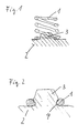
- FIG. 1 shows a presynchronous compression spring 1 and its supports on a sintered shift sleeve carrier 2 at its radially inward end.
- the sintered shift sleeve carrier 2 has a cam-like projection 3, formed in one piece with the sintered shift sleeve carrier, which extends into the presynchronous compression spring 1 and fixes this to the inside diameter in the radial and axial direction.
- the parting plane of the sintering tool runs in the drawing plane so that manufacturing without subsequent processing is possible.
- FIG. 2 shows an additional modification of the embodiment according to FIG. 1, in which the presynchronous compression spring 1 is better fixed in the radial direction.
- the cam-like projection 3 has an undercut 4 on the cam base which can be removed from the sintering tool and into which the presynchronous compression spring 1 is locked with its first gear.
- the presynchronous compression spring 1 can be preassembled in a captive manner on the sintered shift sleeve carrier 2.
- the mass of the presynchronous compression spring is decoupled with regard to the centrifugal force effect, as a result of which the influence of mass on the switching force is minimized at different speeds.
Landscapes
- Engineering & Computer Science (AREA)
- Mechanical Engineering (AREA)
- General Engineering & Computer Science (AREA)
- Manufacturing & Machinery (AREA)
- Powder Metallurgy (AREA)
- Mechanical Operated Clutches (AREA)
Abstract
Description
- Figur 1
- einen Teilquerschnitt eines gesinterten Schaltmuffenträgers im Bereich einer Vorsynchrondruckfeder gemäß der Erfindung und
- Figur 2
- eine Variante der Erfindung nach Figur 1 in entsprechender Darstellung.
Claims (3)
- Gesinterter Schaltmuffenträger (2) mit Auflagern für Vorsynchrondruckfedern (1) zu deren Führung in axialer und radialer Richtung, dadurch gekennzeichnet, dass jedes Vorsynchrondruckfederauflager aus jeweils einem im Sinterverfahren gleichzeitig mit dem Schaltmuffenträger (2) hergestellten Zentriervorsprung (3) des Schaltmuffenträgers (2) in radialer Richtung besteht, der die zugehörige Vorsynchrondruckfeder (1) an ihrem Innendurchmesser zentriert.
- Schaltmuffenträger (2) nach Anspruch 1, dadurch gekennzeichnet, dass die Trennebene des Sinterwerkzeugs mittig durch den Zentriervorsprung (3) des Schaltmuffenträgers (2) verläuft.
- Schaltmuffenträger (2) nach Anspruch 1 oder 2, dadurch gekennzeichnet, dass der Zentriervorsprung (3) eine Hinterschneidung (4) besitzt, die so gestaltet ist, dass die Vorsynchrondruckfeder (1) mit einem Gang in diese eingerastet werden kann.
Applications Claiming Priority (2)
| Application Number | Priority Date | Filing Date | Title |
|---|---|---|---|
| DE2001135639 DE10135639A1 (de) | 2001-07-21 | 2001-07-21 | Gesinterter Schaltmuffenträger |
| DE10135639 | 2001-07-21 |
Publications (2)
| Publication Number | Publication Date |
|---|---|
| EP1277981A1 true EP1277981A1 (de) | 2003-01-22 |
| EP1277981B1 EP1277981B1 (de) | 2007-12-19 |
Family
ID=7692670
Family Applications (1)
| Application Number | Title | Priority Date | Filing Date |
|---|---|---|---|
| EP02011698A Expired - Lifetime EP1277981B1 (de) | 2001-07-21 | 2002-06-04 | Gesinterter Schaltmuffenträger |
Country Status (2)
| Country | Link |
|---|---|
| EP (1) | EP1277981B1 (de) |
| DE (2) | DE10135639A1 (de) |
Citations (3)
| Publication number | Priority date | Publication date | Assignee | Title |
|---|---|---|---|---|
| FR2752279A1 (fr) * | 1996-08-09 | 1998-02-13 | Volkswagen Ag | Piece d'arret pour dispositif de synchronisation |
| DE19922325C1 (de) | 1999-05-14 | 2000-07-13 | Daimler Chrysler Ag | Schaltmuffenträger |
| EP1184585A1 (de) * | 2000-08-29 | 2002-03-06 | Peugeot Citroen Automobiles | Einrichtung um eine Kugel in der Nabe einer Synchronisiereinrichtung für Kraftfahrzeuge zu halten |
Family Cites Families (1)
| Publication number | Priority date | Publication date | Assignee | Title |
|---|---|---|---|---|
| DE7042040U (de) * | 1973-02-22 | Zahnradfabrik Friedrichshafen Ag | Zahnradgetriebe mit Synchronisierung |
-
2001
- 2001-07-21 DE DE2001135639 patent/DE10135639A1/de not_active Withdrawn
-
2002
- 2002-06-04 EP EP02011698A patent/EP1277981B1/de not_active Expired - Lifetime
- 2002-06-04 DE DE50211389T patent/DE50211389D1/de not_active Expired - Fee Related
Patent Citations (3)
| Publication number | Priority date | Publication date | Assignee | Title |
|---|---|---|---|---|
| FR2752279A1 (fr) * | 1996-08-09 | 1998-02-13 | Volkswagen Ag | Piece d'arret pour dispositif de synchronisation |
| DE19922325C1 (de) | 1999-05-14 | 2000-07-13 | Daimler Chrysler Ag | Schaltmuffenträger |
| EP1184585A1 (de) * | 2000-08-29 | 2002-03-06 | Peugeot Citroen Automobiles | Einrichtung um eine Kugel in der Nabe einer Synchronisiereinrichtung für Kraftfahrzeuge zu halten |
Non-Patent Citations (1)
| Title |
|---|
| GEMEINHOLZER G: "ZF: CONFORT DE PASSAGE ET CONSTRUCTION PLUS COMPACTE POUR LES TRANSMISSIONS DE VOITURES DE SPORT ET DE PUISSANCES ELEVEES, GRACE AU MATERIAU DE FRICTION FRITTE HS 43", INGENIEURS DE L'AUTOMOBILE, RAIP. BOULOGNE, FR, no. 662, 1991, pages 69 - 71, XP000147163, ISSN: 0020-1200 * |
Also Published As
| Publication number | Publication date |
|---|---|
| DE50211389D1 (de) | 2008-01-31 |
| EP1277981B1 (de) | 2007-12-19 |
| DE10135639A1 (de) | 2003-02-06 |
Similar Documents
| Publication | Publication Date | Title |
|---|---|---|
| DE19832729B4 (de) | Synchronkörper mit integriertem Druckstück oder Rastelement | |
| EP0955481B1 (de) | Schiebemuffe einer Synchronisiereinheit für Schaltgetriebe | |
| DE2619479A1 (de) | Verfahren zur ausbildung eines aufnahmeschlitzes fuer einen sprengring in einem keilverzahnten maschinenelement | |
| DE3642115C2 (de) | Verfahren und Anordnung zum Befestigen von Lagerringen | |
| EP3615834B1 (de) | Bremsscheibenanordnung für eine scheibenbremse eines kraftfahrzeugs, verfahren | |
| DE69216045T2 (de) | Abdichtungsvorrichtungen für geradlinig bewegenden machanismus und verfahren zu deren herstellung | |
| DE102019123434A1 (de) | Blechring für ein Rotorblechpaket eines Rotors einer elektrischen Maschine und Verfahren zur Herstellung eines Rotorblechpakets aus mehreren Blechringen | |
| DE102007027161A1 (de) | Lageranordnung | |
| EP0693230B1 (de) | Armierungsring für rotationskörper und verfahren zu seiner herstellung | |
| EP1319861B1 (de) | Lagerung mit einem Gummi-Metalllager für einen Getriebeträger | |
| EP1277981A1 (de) | Gesinterter Schaltmuffenträger | |
| EP1413791A1 (de) | Reibbelagsegment, Reibbelag und Verfahren zu deren Herstellung | |
| DE4127213A1 (de) | Duennringlager | |
| WO2017198404A1 (de) | Verbindungsanordnung zur verbindung einer mehrzahl von tilgermassenelementen einer tilgermasse | |
| DE3416686A1 (de) | Spannrolle | |
| DE19910308B4 (de) | Hydraulisch dämpfendes Gummilager mit Axialanschlägen sowie ein Verfahren zur Herstellung eines solchen hydraulisch dämpfenden Gummilagers mit integrierten Axialanschlägen | |
| DE102018101551A1 (de) | Käfig für ein Wälzlager, Verfahren zum Fertigen des Käfigs sowie ein Käfigrohling | |
| DE10211135B4 (de) | Verfahren und Vorrichtung zur Herstellung eines Formkörpers | |
| DE102016205482A1 (de) | Die Erfindung betrifft eine Arretierung und eine Synchronisiereinrichtung mit einer Arretierung und einem Synchronkörper | |
| DE102010052875A1 (de) | Verfahren zur Herstellung eines Gleichaufgelenks | |
| EP1717470B1 (de) | Lageranordnung mit zweiteiligem Lagerträger | |
| DE102004008420B4 (de) | Vorrichtung zur Dämpfung von Schwingungen und Verfahren zur Herstellung eines kombinierten Gehäuse-Primär- oder Sekundärteil-Teilelementes für Vorrichtungen zur Dämpfung von Schwingungen | |
| DE102013224594B4 (de) | Tilgersystem | |
| DE112017008237T5 (de) | Deckelelement für einen Nockenwellenversteller und Nockenwellenversteller | |
| DE102014223514A1 (de) | Wälzlageraufnahme für eine Wellenlagerung |
Legal Events
| Date | Code | Title | Description |
|---|---|---|---|
| PUAI | Public reference made under article 153(3) epc to a published international application that has entered the european phase |
Free format text: ORIGINAL CODE: 0009012 |
|
| 17P | Request for examination filed |
Effective date: 20021004 |
|
| AK | Designated contracting states |
Kind code of ref document: A1 Designated state(s): AT BE CH CY DE DK ES FI FR GB GR IE IT LI LU MC NL PT SE TR |
|
| AX | Request for extension of the european patent |
Free format text: AL;LT;LV;MK;RO;SI |
|
| AKX | Designation fees paid |
Designated state(s): DE FR GB IT |
|
| 17Q | First examination report despatched |
Effective date: 20070427 |
|
| GRAP | Despatch of communication of intention to grant a patent |
Free format text: ORIGINAL CODE: EPIDOSNIGR1 |
|
| 17Q | First examination report despatched |
Effective date: 20070427 |
|
| GRAS | Grant fee paid |
Free format text: ORIGINAL CODE: EPIDOSNIGR3 |
|
| GRAA | (expected) grant |
Free format text: ORIGINAL CODE: 0009210 |
|
| AK | Designated contracting states |
Kind code of ref document: B1 Designated state(s): DE FR GB IT |
|
| REG | Reference to a national code |
Ref country code: GB Ref legal event code: FG4D Free format text: NOT ENGLISH |
|
| GBT | Gb: translation of ep patent filed (gb section 77(6)(a)/1977) |
Effective date: 20071219 |
|
| REF | Corresponds to: |
Ref document number: 50211389 Country of ref document: DE Date of ref document: 20080131 Kind code of ref document: P |
|
| ET | Fr: translation filed | ||
| PGFP | Annual fee paid to national office [announced via postgrant information from national office to epo] |
Ref country code: IT Payment date: 20080625 Year of fee payment: 7 |
|
| PLBE | No opposition filed within time limit |
Free format text: ORIGINAL CODE: 0009261 |
|
| STAA | Information on the status of an ep patent application or granted ep patent |
Free format text: STATUS: NO OPPOSITION FILED WITHIN TIME LIMIT |
|
| 26N | No opposition filed |
Effective date: 20080922 |
|
| PGFP | Annual fee paid to national office [announced via postgrant information from national office to epo] |
Ref country code: FR Payment date: 20080626 Year of fee payment: 7 |
|
| PGFP | Annual fee paid to national office [announced via postgrant information from national office to epo] |
Ref country code: GB Payment date: 20080626 Year of fee payment: 7 |
|
| PG25 | Lapsed in a contracting state [announced via postgrant information from national office to epo] |
Ref country code: DE Free format text: LAPSE BECAUSE OF NON-PAYMENT OF DUE FEES Effective date: 20090101 |
|
| GBPC | Gb: european patent ceased through non-payment of renewal fee |
Effective date: 20090604 |
|
| REG | Reference to a national code |
Ref country code: FR Ref legal event code: ST Effective date: 20100226 |
|
| PG25 | Lapsed in a contracting state [announced via postgrant information from national office to epo] |
Ref country code: FR Free format text: LAPSE BECAUSE OF NON-PAYMENT OF DUE FEES Effective date: 20090630 |
|
| PG25 | Lapsed in a contracting state [announced via postgrant information from national office to epo] |
Ref country code: GB Free format text: LAPSE BECAUSE OF NON-PAYMENT OF DUE FEES Effective date: 20090604 |
|
| PG25 | Lapsed in a contracting state [announced via postgrant information from national office to epo] |
Ref country code: IT Free format text: LAPSE BECAUSE OF NON-PAYMENT OF DUE FEES Effective date: 20090604 |