EP1277859A2 - Sliver opening arrangement for an open-end spinning machine - Google Patents
Sliver opening arrangement for an open-end spinning machine Download PDFInfo
- Publication number
- EP1277859A2 EP1277859A2 EP02012279A EP02012279A EP1277859A2 EP 1277859 A2 EP1277859 A2 EP 1277859A2 EP 02012279 A EP02012279 A EP 02012279A EP 02012279 A EP02012279 A EP 02012279A EP 1277859 A2 EP1277859 A2 EP 1277859A2
- Authority
- EP
- European Patent Office
- Prior art keywords
- spreading
- rollers
- roller
- open
- end spinning
- Prior art date
- Legal status (The legal status is an assumption and is not a legal conclusion. Google has not performed a legal analysis and makes no representation as to the accuracy of the status listed.)
- Granted
Links
Images


Classifications
-
- D—TEXTILES; PAPER
- D01—NATURAL OR MAN-MADE THREADS OR FIBRES; SPINNING
- D01H—SPINNING OR TWISTING
- D01H4/00—Open-end spinning machines or arrangements for imparting twist to independently moving fibres separated from slivers; Piecing arrangements therefor; Covering endless core threads with fibres by open-end spinning techniques
- D01H4/30—Arrangements for separating slivers into fibres; Orienting or straightening fibres, e.g. using guide-rolls
Definitions
- the invention relates to an open-end spinning device according to the preamble of claim 1.
- DE 40 40 102 A1 shows a device for spinning a Thread, in which the sliver end by an additional Air flow is moved into the set, so that a effective resolution should still be possible if the speed of the opening roller compared to Rotor spinning devices usual speed of opening rollers is significantly reduced. Because the sliver end in the Is pushed in, combing is intensified, essentially through the side flanks of the teeth or Is caused. It is aimed in this way, too sufficient at slower combing speeds Generating friction, through which the fibers are made safe the sliver end or fiber beard are pulled out. It has it turned out, however, that by sucking the Individual fibers with the peripheral speed of the Opening roller are transported so that the individual fibers despite the reduced peripheral speed of the opening roller overall have the same speed as at conventional opening rollers and thus undesirably fast are.
- the generic DE 196 10 960 A1 describes a Open-end spinning process, in which the individual fibers on their Can no longer be slowed down from the sliver to the thread should.
- the individual fibers should immediately after their Detach from the sliver of a precisely defined one mechanically controlled speed.
- the feed device has a very wide feed roller and an equally wide opening roller. So that the number the interventions of dissolving elements in the fiber beard increase.
- the invention has for its object the fiber template for to improve the resolver.
- the spreading device required in relation to multi-stage drafting devices advantageously little space.
- a Generate fiber material template with a more precise dosage and increased uniformity of the amount of fiber fed can be achieved.
- the dissolving process itself will improved. Too high distortions in the direction of fiber flow and the result associated disadvantages can be avoided.
- the spreading device there is a compact device for effective spreading of the Sliver in the transverse direction in a narrow space. It can be one thin fiber material template for the opening roller generated be that over the entire working width of the opening roller enough. This means that the resolution process is flawless low opening roller speed as well as compared to that of Rotor spinning usual opening roller widened opening roller achievable, which is characterized by high dosing accuracy and high Characterized yarn uniformity.
- the distance between each interacting spreading rollers can be changed periodically.
- the tensile stress on the fiber material template acts change periodically and so the spreading process intensify, accelerate and equalize.
- a sliver can be 2 to 3 times, for example Width of the original width can be spread.
- a frequency of periodic change that is much higher is called the rotational frequency of the spreading rollers, the frequency preferably to a value between 8 Hz and 25 Hz is set leads to a high uniformity of the Spreading the fiber material template.
- the depressions can be designed as trapezoidal grooves his. Such a shape is easy to manufacture and it forms deflection edges for the between each interacting spreading rollers guided zigzag Sliver. The sliver is with between the deflection edges a tensile stress builds up, and under the Influence of this tension is effectively spread.
- the depressions and webs are designed so that the webs of the spreading rollers approximately one in the axial direction Form sinusoid. In this way, it is more gentle Spreading.
- the Spreading rollers formed by discs, each on a Shaft are attached, and the peripheral surfaces of the webs form.
- This version is simple and inexpensive produce.
- the limitation to a maximum of two slivers means that the fiber material template predominantly by cross expansion and not mainly due to longitudinal distortion to a thin non-woven fabric has been pulled apart when the opening roller is presented. This allows the uniformity of the Improve the fiber material template.
- a deflection device upstream of the belt spreading device is at such a distance for that from a jug stripped sliver arranged that the sliver at Pull out of the jug between the jug and the deflection device more than the length of the tape of a coil rotation hangs vertically.
- This arrangement enables the Coiler rotation incorrect rotation introduced into the sliver can turn out.
- Such false rotations consist of so-called S and from so-called Z twists, the can happen accidentally when you take off the tape. With the Belt spreading device associated deflection device can safely avoided that the wrong turns in the Break in pairs of spreading rollers and hinder the spreading process.
- a Sliver 1 pulled from the can 2 runs over the Deflection roller 3 of a deflection device 4 and is by a Guide 5 fed to a spreading device 6.
- the distance between the axis of the guide roller 3 and the can 2 a little more than the length of a coil turn.
- the Sliver 1 passes through three of the spreading rollers 7, 8, 9, 10, 11, 12 formed pairs of rollers and is in a spread state presented as a thin nonwoven fabric 13 of the opening device 14.
- the feed trough 15 presses the spread sliver 1 against the Feed roller 16 and forms a with the feed roller 16 Nip that the end of the sliver 1, the so-called Beard, holds back.
- the opening roller 17 combs the fiber beard and dissolves the sliver down to the individual fiber. there rotates the opening roller 17 in the direction of arrow 18.
- Die Fibers are taken over by a vacuumed take-off roller 19 and brought together into a narrow ribbon.
- the direction of rotation of the take-off roller 19 is indicated by the arrow 20 indicated.
- the take-off roller 19 and the pinch roller 21 form a clamping line that is traversed by the ribbon.
- the air spinning device 22 generates an air vortex which is used for Thread formation serves.
- Such air spinning devices are known for example from DE 196 10 960.
- the thread 23 passes a fume cupboard 24 and becomes one For reasons of simplification, winding unit not shown promoted.
- the band spreading device 6 of Figure 2 is opposite the Figure 1 enlarged and shown in more detail.
- the Sliver 1 is in the guide 5 after the deflection first pair of rollers formed from the spreading rollers 7, 8 moved in and spread there. Spreading it will Sliver 1 thinner.
- the sliver 1 then runs through the spreading rollers 9 and 10 of the second pair of spreading rollers and finally the spreading rollers 11 and 12 of the third Spreading roller pair and is as thin, over the entire Working width of spread sliver 1 of the feed roller 16 supplied, which forms a clamping line with the feed trough 15.
- the high-speed opening roller 17 combs the fibers from the designated as fiber beard 25 end of the sliver 1 and dissolves the sliver 1 up to the individual fiber.
- the lower spreading rollers 8, 10, 12 are non-rotatable with the Gears 26, 27, 28 connected.
- the intermediate wheels 29, 30 provide a drive connection between the gears 26, 27, 28 of the lower spreading rollers 8, 10, 12 ago.
- the Intermediate wheel 30 is rotationally fixed to pulley 31 connected by means of the drive belt 32 over the Pulley 33 is driven.
- the pulley 33 is in turn, non-rotatably connected to the feed roller 16.
- the Pulley 33 is driven by motor 35 by means of drive belt 34 driven.
- the translation between the feed roller 16 and the lower spreading rollers 8, 10, 12 is chosen so that the Peripheral speed of the feed roller 16 and Spreading rollers 8, 10, 12 is the same.
- the axis 36 of the upper spreading roller 9 is on an arm of the Angle lever 37 attached.
- the angle lever 37 is in the With respect to the housing 40 fixed axis 38 and has a bolt 39 attached to the other arm.
- the Bolt 39 engages in the elongated hole 41 of the coupling rod 42.
- the upper spreading rollers 7 and 11 on the Angle levers 43 and 44 are pivotally mounted.
- the bolts 45, 46 of the angle levers 43, 44 also engage in each Elongated hole of the coupling rods 47, 48 a.
- the coupling rod 42 is pivotable with its end on the Bolt 45, the coupling rod 48 in the same way on the Bolt 39 attached so that the three angle levers 37, 43, 44th articulated and pivotable together are.
- pivoting the angle lever 37, 43, 44 against the upper spreading rollers 7, 9, 11 from the lower spreading rollers 8, 10, 12 are lifted off for example, to be able to insert new slivers.
- the lever knob 57 detects the locking lever 55 upwards pivoted, whereby the nose 56 disengages from the housing 40 and the fixation of the coupling rods 42, 47, 48 is released.
- the lever button 57 in the Representation of Figure 2 By subsequently moving the lever button 57 in the Representation of Figure 2 to the left, the angle lever 37, 43, 44 pivoted counterclockwise and the top Spreading rollers 7, 9, 11 raised.
- the upper spreading rollers 7, 9, 11 dodge upwards.
- the deflection takes place against the Tensile force caused by the respective tension spring 52, 53, 54 is applied as part of the game by the Dimensions of the elongated holes of the coupling rods 42, 47, 48 is limited.
- Figure 3 shows a section through the second pair of spreading rollers the band spreading device 6 shown in FIG Grip grooves and webs of the two spreading rollers 9, 10 into each other and form a zigzag Gap.
- the distance between the spreading rollers 9, 10 is so dimensioned that a sliver 1 of 7 ktex in the space can be drawn in without the upper spreading roller 9 to raise.
- the shaft 58 of the lower spreading roller 10 is on Housing 40 mounted and is driven via the gear 27.
- the spreading roller 10 laterally has rims 59, 60 on which the upper spreading roller 9 rests with its rims 61, 62.
- the upper spreading roller 9 is rotatably mounted on the axis 63.
- the Axis 63 is fixed to the angle lever 37.
- the working width of the roller pairs is the working width of the feed roller 16 customized.
- the sliver 1 is shown in FIG. 3 already largely over the width of the spreading rollers 9, 10 spread. After the spread by the third Spreading roller pair can the sliver 1 of the feed roller 16 over spread the entire working width.
- Figure 4 shows the space between the spreading rollers 9 and 10 in an enlarged view.
- the webs 64 of the lower Spreading roller 10 engage in the grooves 65 of the upper Spreading roller 9 and the webs 66 of the upper spreading roller 9 in the grooves 67 of the lower spreading roller 10.
- the sliver 1 runs zigzag in the space between the two Spreading rollers 9, 10 and when entering the pair of rollers each in the area between the webs 64 and the webs 66 subjected to a tensile stress and thereby spread.
- the Spreading process of the sliver 68 can be carried out more gently.
- FIG. 6 shows an alternative embodiment of the The subject matter.
- the sliver 71 is replaced by a Spreading roller pair performed, in which both the upper Spreading roller 72 as well as the lower spreading roller 73 disks 74, 75, each fastened to a shaft 76, 77 are, and their peripheral surfaces form webs 99, 100. Between the disks 74, 75 recesses 97, 98 are formed.
- This Execution of the spreading rollers 72, 73 is simple and manufacture inexpensively.
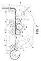
- FIG. 7 shows the side view of a belt spreading device 78 with up and down moving upper spreading rollers 79, 81 and stationary lower spreading rollers 80, 82.
- the opening device with the feed roller 16 is further in connection with Figure 2 described above.
- the sliver 1 passes a guide 5 and a deflecting roller 83 before it comes out of the upper Spreading roller 79 and the lower spreading roller 80 formed first spreading roller pair is supplied. Before it was the Feed roller 16 is submitted, it passes through a second the upper spreading roller 81 and the lower spreading roller 82 formed spreading roller pair.
- the height of the stationary lower spreading rollers 80, 82 is chosen so that Sliver 1 can run above the spreading rollers 80, 82, if there is between the deflection roller 83 and the feed roller 16 is pulled tight.
- the axes 84, 85 of the spreading rollers 79, 81 are on Angle lever 86 attached; the lower spreading rollers 80, 82 are mounted stationary on the housing 87.
- the storage corresponds to the Bearing of the spreading rollers 8, 10, 12 shown in Figure 2
- Angle lever 86 and the dashed line Swivel levers 88 are connected in a rotationally fixed manner to the shaft 89 and can be pivoted together about the axis of rotation of shaft 89.
- On The end of the pivot lever 88 is blown away by means of the crank rod 90 forth.
- the other end of the crank rod 90 engages the crank disk 91.
- the crank disc 91 is from Motor 92 driven.
- the speed of the crank disk 91 is between 500 revolutions per minute and 1,500 revolutions per minute Minute.
- the crank drive is a buffer element trained that when entering thickened tape or Belt twists no jam occurs.
- the lower spreading rollers 80, 82 are by means of Driving belt 93 via the intermediate gear 94 and the gear wheels 95, 96 rotated.
- the drive belt 93 also drives the Deflection roller 83.
- the gear ratios are like this chosen that both the deflection roller 83 and the Spreading rollers 79, 80, 81, 82 and the feed roller 16 die have the same peripheral speed.
- the sliver 1 loosens with each upward movement of the upper spreading rollers 79, 81 in the respective spreading roller pair the grooves.
- the new point of contact between fiber material and the webs is the downward movement of the Spreading rollers 79, 81 mostly shifted somewhat to the side.
- the Sliver 1 is not only more effective, but also spread more evenly.
Landscapes
- Engineering & Computer Science (AREA)
- Mechanical Engineering (AREA)
- Textile Engineering (AREA)
- Spinning Or Twisting Of Yarns (AREA)
- Preliminary Treatment Of Fibers (AREA)
- Nonwoven Fabrics (AREA)
Abstract
Description
Die Erfindung betrifft eine Offenend-Spinnvorrichtung gemäß
dem Oberbegriff des Anspruchs 1.The invention relates to an open-end spinning device according to
the preamble of
Neben dem Rotorspinnverfahren wird auch bei anderen Offenend-Spinnverfahren, wie Friktionsspinnen oder Luftspinnen, ein Faserband mittels einer Auflösewalze zu Einzelfasern aufgelöst. Bei derartigen Spinnverfahren ist es zur Vermeidung von Faserstauchungen üblicherweise erwünscht, daß das Fasermaterial auf seinem gesamten Weg von der Zuführeinrichtung der Auflösewalze bis zur Abzugseinrichtung des Fadens ständig beschleunigt werden kann, ohne daß dabei die Abzugsgeschwindigkeit zu hohe Werte annehmen muß. Es kann jedoch mit erheblichen Nachteilen verbunden sein, dafür die Drehzahl der Auflösewalze beliebig abzusenken. Beim Absenken der Drehzahl der Auflösewalze besteht die Gefahr, daß die Auflösefunktion wesentlich beeinträchtigt wird. Die für das erwünschte Auflösen des Fasermaterials bis zur Einzelfaser erforderliche Anzahl der Eingriffe von Auflöseelementen, wie Nadeln oder Sägezähnen, in den Faserbart kann nicht erreicht werden.In addition to the rotor spinning process, other open-end spinning processes, such as friction spiders or aerial spiders Sliver by means of an opening roller to individual fibers dissolved. With such spinning processes it is to be avoided of fiber compression usually desirable that Fiber material all the way from the Feed device of the opening roller up to the take-off device of the thread can be accelerated continuously without doing so the take-off speed must be too high. It can However, there are considerable disadvantages, for which the Reduce the speed of the opening roller as desired. When lowering the speed of the opening roller there is a risk that the Dissolving function is significantly impaired. The for that Desired dissolution of the fiber material down to the individual fiber required number of interventions by dissolving elements, such as Needles or saw teeth, in the fiber beard can not be reached become.
Sowohl die Menge der ausgekämmten Fasern wie auch das Gleichbleiben dieser Menge ist unzureichend für einen einwandfreien Faden.Both the amount of combed fibers and that Keeping this amount is insufficient for one flawless thread.
Die DE 40 40 102 A1 zeigt eine Vorrichtung zum Erspinnen eines
Fadens, bei der das Faserbandende durch eine zusätzliche
Luftströmung in die Garnitur hineinbewegt wird, so daß eine
wirkungsvolle Auflösung auch dann noch möglich sein soll, wenn
die Drehzahl der Auflösewalze gegenüber der bei
Rotorspinnvorrichtungen üblichen Drehzahl von Auflösewalzen
wesentlich reduziert ist. Weil das Faserbandende in die
Garnitur hineingedrückt wird, wird das Auskämmen intensiviert,
das im wesentlichen durch die Seitenflanken der Zähne oder
Nadeln bewirkt wird. Es wird auf diese Weise angestrebt, auch
bei langsameren Kämmgeschwindigkeiten eine ausreichende
Reibungsmitnahme zu erzeugen, durch die die Fasern sicher aus
dem Faserbandende oder Faserbart herausgezogen werden. Es hat
sich jedoch herausgestellt, daß durch das Ansaugen der
Einzelfasern diese mit der Umfangsgeschwindigkeit der
Auflösewalze transportiert werden, so daß die Einzelfasern
trotz verringerter Umfangsgeschwindigkeit der Auflösewalze
insgesamt die gleiche Geschwindigkeit haben wie bei
herkömmlichen Auflösewalzen und damit unerwünscht schnell
sind.
Auch die gattungsbildende DE 196 10 960 A1 beschreibt ein Offenend-Spinnverfahren, bei dem die Einzelfasern auf ihrem Weg vom Faserband bis zum Faden nicht mehr verlangsamt werden sollen. Die Einzelfasern sollen unmittelbar nach ihrem Herauslösen aus dem Faserband einer genau festgelegten mechanisch kontrollierten Geschwindigkeit unterworfen werden. Die Zuführeinrichtung weist eine sehr breite Zuführwalze und eine ebenso breite Auflösewalze auf. Damit läßt sich die Zahl der Eingriffe von Auflöseelementen in den Faserbart erhöhen.The generic DE 196 10 960 A1 describes a Open-end spinning process, in which the individual fibers on their Can no longer be slowed down from the sliver to the thread should. The individual fibers should immediately after their Detach from the sliver of a precisely defined one mechanically controlled speed. The feed device has a very wide feed roller and an equally wide opening roller. So that the number the interventions of dissolving elements in the fiber beard increase.
Als Möglichkeit zum Erzielen einer breiten Faservorlage wird offenbart, mehrere, nämlich fünf, Faserbänder nebeneinander gleichzeitig vorzulegen. Das Zuführen von mehreren Faserbändern zu einer Spinnstelle führt zu erheblichem Aufwand. Neben dem Aufwand durch Vervielfachung der Zuführwege mit den erforderlichen Zuführelementen muß zum Beispiel der Raum für eine entsprechende Anzahl von Spinnkannen an jeder Spinnstelle zur Verfügung stehen. Dies führt bei einer Spinnmaschine mit ihrer Vielzahl von Spinnstellen zu einem enormen Platzbedarf. Außerdem ergeben sich zwischen der Faserbandvorlage und dem gesponnenen Garn sehr hohe Verzüge, die die Gleichmäßigkeit beziehungsweise die Einhaltung der Garnfeinheit gefährden.As a way to achieve a broad fiber template discloses several, namely five, slivers side by side to submit simultaneously. Feeding several Sliver to a spinning station leads to considerable Expenditure. In addition to the effort by multiplying the feed paths with the necessary feed elements, for example, the Space for an appropriate number of spinning cans on each Spinning station are available. This leads to a Spinning machine with its multitude of spinning positions in one enormous space requirement. In addition, between the Sliver and the spun yarn very high warpage, which the uniformity or compliance with Threaten yarn count.
Der Erfindung liegt die Aufgabe zugrunde, die Faservorlage für die Auflöseeinrichtung zu verbessern.The invention has for its object the fiber template for to improve the resolver.
Diese Aufgabe wird erfindungsgemäß durch eine Offenend-Spinnvorrichtung
mit den Merkmalen des Anspruchs 1 gelöst.This object is achieved by an open-end spinning device
solved with the features of
Vorteilhafte Ausgestaltungen der Erfindung sind Gegenstand der Unteransprüche.Advantageous embodiments of the invention are the subject of Dependent claims.
Mit einem erfindungsgemäß ausgebildeten Spreizwalzenpaar, das der Auflöseeinrichtung im Faserfluß vorgeordnet ist, läßt sich zum Beispiel ein Faserband über die gesamte Arbeitsbreite der Auflösewalze verteilen und vergleichmäßigen, indem es einem Spreizvorgang unterworfen wird. Dabei läßt sich eine relativ dünne Fasermaterialvorlage erzielen. Die Bandspreizvorrichtung benötigt im Verhältnis zu mehrstufigen Verzugseinrichtungen vorteilhaft wenig Raum.With a pair of spreading rollers designed according to the invention, the is arranged upstream of the dissolving device in the fiber flow for example a sliver across the entire working width of the Distribute and equalize the opening roller by giving it Spreading process is subjected. It can be a relative achieve a thin fiber material template. The spreading device required in relation to multi-stage drafting devices advantageously little space.
Mittels der vorliegenden Erfindung läßt sich eine Fasermaterialvorlage erzeugen, mit der eine genauere Dosierung und eine erhöhte Gleichmäßigkeit der eingespeisten Fasermenge erreicht werden können. Der Auflösevorgang selbst wird verbessert. Zu hohe Verzüge in Faserflußrichtung und die damit verbundenen Nachteile können vermieden werden.By means of the present invention, a Generate fiber material template with a more precise dosage and increased uniformity of the amount of fiber fed can be achieved. The dissolving process itself will improved. Too high distortions in the direction of fiber flow and the result associated disadvantages can be avoided.
Mit der erfindungsgemäßen Bandspreizvorrichtung liegt eine kompakte Einrichtung zum wirkungsvollen Spreizen des Faserbandes in Querrichtung auf engem Raum vor. Es kann eine dünne Fasermaterialvorlage für die Auflösewalze erzeugt werden, die über die gesamte Arbeitsbreite der Auflösewalze reicht. Damit ist ein einwandfreier Auflösevorgang bei niedriger Auflösewalzendrehzahl sowie bei gegenüber der beim Rotorspinnen üblichen Auflösewalze verbreiterten Auflösewalze erzielbar, der sich durch hohe Dosiergenauigkeit und hohe Garngleichmäßigkeit auszeichnet.With the spreading device according to the invention there is a compact device for effective spreading of the Sliver in the transverse direction in a narrow space. It can be one thin fiber material template for the opening roller generated be that over the entire working width of the opening roller enough. This means that the resolution process is flawless low opening roller speed as well as compared to that of Rotor spinning usual opening roller widened opening roller achievable, which is characterized by high dosing accuracy and high Characterized yarn uniformity.
Vorzugsweise ist der Abstand zwischen den jeweils zusammenwirkenden Spreizwalzen periodisch veränderbar. Damit läßt sich die Zugspannung, die auf die Fasermaterialvorlage einwirkt, periodisch verändern und so der Spreizvorgang intensivieren, beschleunigen und vergleichmäßigen.Preferably, the distance between each interacting spreading rollers can be changed periodically. In order to can the tensile stress on the fiber material template acts, change periodically and so the spreading process intensify, accelerate and equalize.
In einer bevorzugten Ausführungsform sind zwei aufeinanderfolgende Spreizwalzenpaare so miteinander gekoppelt, daß sich deren Spreizwalzenabstände gegensinnig so ändern, daß sich jeweils bei einem Spreizwalzenpaar der Abstand zwischen den zusammenwirkenden Spreizwalzen verringert, während sich bei dem anderen Spreizwalzenpaar der Abstand vergrößert. Sind die beiden Spreizwalzenpaare mechanisch gekoppelt und ist ein gemeinsamer Antrieb zur Erzeugung der periodischen Änderung des Walzenabstandes vorhanden, ist der Antrieb für die periodische Abstandsänderung besonders einfach und kostensparend ausgeführt. Die Spreizwirkung wird noch mehr verstärkt. Auf diese Weise kann ein Faserband zum Beispiel auf die 2- bis 3-fache Breite der ursprünglichen Breite gespreizt werden.In a preferred embodiment there are two successive spreading roller pairs with each other coupled that their spreading roller distances in opposite directions change that each with a pair of spreading rollers Distance between the interacting spreading rollers decreased, while the other pair of spreading rollers Distance increased. Are the two spreading roller pairs mechanically coupled and is a common drive for Generation of the periodic change of the roller spacing is present, the drive for the periodic Distance change particularly easy and cost-saving executed. The spreading effect is increased even more. On in this way, a sliver can be 2 to 3 times, for example Width of the original width can be spread.
Eine Frequenz der periodischen Änderung, die wesentlich höher ist als die Drehfrequenz der Spreizwalzen, wobei die Frequenz vorzugsweise auf einen Wert zwischen 8 Hz und 25 Hz eingestellt ist, führt zu einer hohen Gleichmäßigkeit der Spreizung der Fasermaterialvorlage.A frequency of periodic change that is much higher is called the rotational frequency of the spreading rollers, the frequency preferably to a value between 8 Hz and 25 Hz is set leads to a high uniformity of the Spreading the fiber material template.
Die Vertiefungen können als trapezförmige Nuten ausgebildet sein. Eine derartige Form läßt sich einfach herstellen und sie bildet Umlenkkanten für das zwischen den jeweils zusammenwirkenden Spreizwalzen zickzackförmig geführte Faserband. Zwischen den Umlenkkanten wird das Faserband mit einer sich aufbauenden Zugspannung beaufschlagt, und unter dem Einfluß dieser Zugspannung wirkungsvoll gespreizt wird.The depressions can be designed as trapezoidal grooves his. Such a shape is easy to manufacture and it forms deflection edges for the between each interacting spreading rollers guided zigzag Sliver. The sliver is with between the deflection edges a tensile stress builds up, and under the Influence of this tension is effectively spread.
Alternativ sind die Vertiefungen und Stege so ausgeführt, daß die Stege der Spreizwalzen in Achsrichtung annähernd eine Sinusform bilden. Auf diese Weise erfolgt eine schonendere Spreizung.Alternatively, the depressions and webs are designed so that the webs of the spreading rollers approximately one in the axial direction Form sinusoid. In this way, it is more gentle Spreading.
In einer alternativen Ausführungsform der Erfindung sind die Spreizwalzen durch Scheiben gebildet, die jeweils auf einer Welle befestigt sind, und deren Umfangsflächen die Stege bilden. Diese Ausführung läßt sich einfach und kostengünstig herstellen.In an alternative embodiment of the invention, the Spreading rollers formed by discs, each on a Shaft are attached, and the peripheral surfaces of the webs form. This version is simple and inexpensive produce.
Die Begrenzung auf maximal zwei Faserbänder führt dazu, daß die Fasermaterialvorlage überwiegend durch Querspreizung und nicht überwiegend durch Längsverzug zu einem dünnen Faservlies auseinandergezogen worden ist, wenn sie der Auflösewalze vorgelegt wird. Damit läßt sich die Gleichmäßigkeit der Fasermaterialvorlage verbessern.The limitation to a maximum of two slivers means that the fiber material template predominantly by cross expansion and not mainly due to longitudinal distortion to a thin non-woven fabric has been pulled apart when the opening roller is presented. This allows the uniformity of the Improve the fiber material template.
Eine der Bandspreizvorrichtung vorgelagerte Umlenkvorrichtung ist in einem solchen Abstand für das aus einer Kanne abgezogene Faserband angeordnet, daß das Faserband beim Abziehen aus der Kanne zwischen Kanne und Umlenkeinrichtung mehr als die Bandlänge einer Coilerdrehung senkrecht hängt. Diese Anordnung ermöglicht es, daß sich durch die Coilerdrehung in das Faserband eingebrachte Falschdrehung herausdrehen kann. Derartige Falschdrehungen bestehen aus sogenannten S- und aus sogenannten Z-Verdrehungen, die zufällig beim Ablegen des Bandes entstehen können. Mit der der Bandspreizvorrichtung zugeordneten Umlenkeinrichtung kann sicher vermieden werden, daß die Falschdrehungen in die Spreizwalzenpaare einlaufen und den Spreizvorgang behindern.A deflection device upstream of the belt spreading device is at such a distance for that from a jug stripped sliver arranged that the sliver at Pull out of the jug between the jug and the deflection device more than the length of the tape of a coil rotation hangs vertically. This arrangement enables the Coiler rotation incorrect rotation introduced into the sliver can turn out. Such false rotations consist of so-called S and from so-called Z twists, the can happen accidentally when you take off the tape. With the Belt spreading device associated deflection device can safely avoided that the wrong turns in the Break in pairs of spreading rollers and hinder the spreading process.
Weitere Einzelheiten der Erfindung werden anhand der Darstellung der Figuren erläutert.Further details of the invention are based on the Representation of the figures explained.
Es zeigt:
- Fig. 1
- eine Prinzipdarstellung einer Spinnstelle mit einer Bandspreizvorrichtung,
- Fig. 2
- die Bandspreizeinrichtung der
Figur 1 in Seitenansicht in vereinfachter Darstellung, - Fig. 3
- einen Schnitt A-A durch ein Spreizwalzenpaar der in
Figur 2 dargestellten Bandspreizvorrichtung, - Fig. 4
- das Ineinandergreifen zusammenwirkender Spreizwalzen in
einem vergrößerten Ausschnitt der
Figur 3, - Fig. 5
- einen Schnitt durch ein teilweise dargestelltes Spreizwalzenpaar mit sinusförmigem Profil,
- Fig. 6
- einen Schnitt durch ein Spreizwalzenpaar, dessen Spreizwalzen Scheiben aufweisen,
- Fig. 7
- eine Bandspreizvorrichtung mit jeweils zusammenwirkenden Spreizwalzen, deren Abstand zueinander periodisch veränderbar ist.
- Fig. 1
- 1 shows a schematic diagram of a spinning station with a belt spreading device,
- Fig. 2
- 1 in side view in a simplified representation,
- Fig. 3
- 3 shows a section AA through a pair of spreading rollers of the band spreading device shown in FIG. 2,
- Fig. 4
- the intermeshing of interacting spreading rollers in an enlarged detail of FIG. 3,
- Fig. 5
- 2 shows a section through a pair of spreading roller pairs with a sinusoidal profile,
- Fig. 6
- a section through a pair of spreading rollers, the spreading rollers have disks,
- Fig. 7
- a belt spreading device, each with interacting spreading rollers, the distance between which can be changed periodically.
An der in Figur 1 dargestellten Spinnstelle wird ein
Faserband 1 aus der Kanne 2 abgezogen, läuft über die
Umlenkrolle 3 einer Umlenkeinrichtung 4 und wird durch eine
Führung 5 einer Bandspreizvorrichtung 6 zugeführt. Der Abstand
zwischen der Achse der Umlenkrolle 3 und der Kanne 2 beträgt
etwas mehr als die Bandlänge einer Coilerdrehung. Auf dieser
Strecke hängt das Faserband 1 frei, und vereinzelt auftretende
Falschdrehungen im Faserband 1 können sich herausdrehen. Das
Faserband 1 durchläuft drei von den Spreizwalzen 7, 8, 9, 10,
11, 12 gebildete Walzenpaare und wird in gespreiztem Zustand
als dünnes Faservlies 13 der Auflöseeinrichtung 14 vorgelegt.
Die Speisemulde 15 preßt das gespreizte Faserband 1 gegen die
Einzugswalze 16 und bildet mit der Einzugswalze 16 eine
Klemmstelle, die das Ende des Faserbandes 1, den sogenannten
Faserbart, zurückhält. Die Auflösewalze 17 kämmt den Faserbart
aus und löst das Faserband bis zur Einzelfaser auf. Dabei
rotiert die Auflösewalze 17 in Richtung des Pfeiles 18. Die
Fasern werden von einer besaugten Abnahmewalze 19 übernommen
und zu einem schmalen Faserbändchen zusammengeführt. Die
Drehrichtung der Abnahmewalze 19 ist durch den Pfeil 20
angedeutet. Die Abnahmewalze 19 und die Klemmrolle 21 bilden
eine Klemmlinie, die von dem Faserbändchen durchlaufen wird.At the spinning position shown in Figure 1 is a
Die Luftspinneinrichtung 22 erzeugt einen Luftwirbel, der zur
Fadenbildung dient. Derartige Luftspinneinrichtungen sind
beispielsweise aus der DE 196 10 960 bekannt. Der Faden 23
passiert eine Abzugseinrichtung 24 und wird zu einer aus
Vereinfachungsgründen nicht dargestellten Spulstelle
befördert.The
Die Bandspreizvorrichtung 6 der Figur 2 ist gegenüber der
Figur 1 vergrößert und detaillierter dargestellt. Das
Faserband 1 wird nach dem Umlenken in der Führung 5 in das
erste aus den Spreizwalzen 7, 8 gebildete Walzenpaar
eingezogen und dort gespreizt. Durch das Spreizen wird das
Faserband 1 dünner. Anschließend durchläuft das Faserband 1
die Spreizwalzen 9 und 10 des zweiten Spreizwalzenpaares und
schließlich die Spreizwalzen 11 und 12 des dritten
Spreizwalzenpaares und wird als dünnes, über die gesamte
Arbeitsbreite gespreiztes Faserband 1 der Einzugswalze 16
zugeführt, die mit der Speisemulde 15 eine Klemmlinie bildet.
Die schnellaufende Auflösewalze 17 kämmt die Fasern aus dem
als Faserbart 25 bezeichneten Ende des Faserbandes 1 aus und
löst das Faserband 1 dabei bis zur Einzelfaser auf.The
Die unteren Spreizwalzen 8, 10, 12 sind drehfest mit den
Zahnrädern 26, 27, 28 verbunden. Die Zwischenräder 29, 30
stellen eine Antriebsverbindung zwischen den Zahnrädern 26,
27, 28 der unteren Spreizwalzen 8, 10, 12 her. Das
Zwischenrad 30 ist drehfest mit der Riemenscheibe 31
verbunden, die mittels des Treibriemens 32 über die
Riemenscheibe 33 angetrieben wird. Die Riemenscheibe 33 ist
ihrerseits drehfest mit der Einzugswalze 16 verbunden. Die
Riemenscheibe 33 wird mittels des Treibriemens 34 vom Motor 35
angetrieben. Die Übersetzung zwischen der Einzugswalze 16 und
den unteren Spreizwalzen 8, 10, 12 ist so gewählt, daß die
Umfangsgeschwindigkeit von der Einzugswalze 16 und den
Spreizwalzen 8, 10, 12 gleich ist.The lower spreading
Die Achse 36 der oberen Spreizwalze 9 ist an einem Arm des
Winkelhebels 37 befestigt. Der Winkelhebel 37 ist um die im
Hinblick auf das Gehäuse 40 ortsfeste Achse 38 schwenkbar und
weist einen am anderen Arm befestigten Bolzen 39 auf. Der
Bolzen 39 greift in das Langloch 41 der Koppelstange 42 ein.
In gleicher Weise sind die oberen Spreizwalzen 7 und 11 an den
Winkelhebeln 43 und 44 verschwenkbar gelagert. Die Bolzen 45,
46 der Winkelhebel 43, 44 greifen ebenfalls jeweils in ein
Langloch der Koppelstangen 47, 48 ein.The
Die Koppelstange 42 ist mit ihrem Ende schwenkbar auf den
Bolzen 45, die Koppelstange 48 in gleicher Weise auf den
Bolzen 39 aufgesteckt, so daß die drei Winkelhebel 37, 43, 44
gelenkig miteinander verbunden und gemeinsam verschwenkbar
sind. Durch das Verschwenken der Winkelhebel 37, 43, 44 gegen
den Uhrzeigersinn können die oberen Spreizwalzen 7, 9, 11 von
den unteren Spreizwalzen 8, 10, 12 abgehoben werden, um
beispielsweise neue Faserbänder einlegen zu können.The
An den Bolzen 45, 39, 46 der Winkelhebel 43, 37, 44 und an den
Bolzen 49, 50, 51, die an den Koppelstangen 47, 42, 48
befestigt sind, sind Zugfedern 52, 53, 54 eingehängt. Werden
nach dem Einlegen von Faserbändern die Koppelstangen 42, 47,
48 manuell in der Darstellung der Figur 2 nach rechts gezogen,
verschieben sich die Langlöcher in den Koppelstangen 42, 47,
48 gegenüber den Bolzen 39, 45, 46, und die Bolzen 39, 45, 46
und damit die Winkelhebel 37, 43, 44 werden mittels der
Zugfedern 52, 53, 54 mit einer Zugkraft beaufschlagt.On the
Unter der Wirkung dieser Zugkraft schwenken die
Winkelhebel 37, 43, 44 im Uhrzeigersinn, bis die oberen
Spreizwalzen 7, 9, 11 eine Endposition erreicht haben. In
dieser Endposition werden die Koppelstangen 42, 47, 48 durch
den Sperrhebel 55 fixiert. Der Sperrhebel 55 ist um den
Bolzen 49 schwenkbar. Das Fixieren erfolgt mittels Einhaken
der Nase 56 am Gehäuse 40.Under the effect of this traction, they swivel
Angle levers 37, 43, 44 clockwise until the top
Spreading
Zum manuellen Abheben der oberen Spreizwalzen 7, 9, 11 wird
der Hebelknopf 57 erfaßt, der Sperrhebel 55 nach oben
geschwenkt, wodurch die Nase 56 vom Gehäuse 40 ausklinkt und
die Fixierung der Koppelstangen 42, 47, 48 aufgehoben wird.
Durch anschließendes Bewegen des Hebelknopfes 57, in der
Darstellung der Figur 2 nach links, werden die Winkelhebel 37,
43, 44 gegen den Uhrzeigersinn geschwenkt und die oberen
Spreizwalzen 7, 9, 11 angehoben.For manual lifting of the upper spreading
Läuft eine Bandverdickung oder Bandverdrehung in ein
Spreizwalzenpaar ein, können die oberen Spreizwalzen 7, 9, 11
jeweils nach oben ausweichen. Die Auslenkung erfolgt gegen die
Zugkraft, die durch die jeweilige Zugfeder 52, 53, 54
aufgebracht wird, im Rahmen des Spiels, das durch die
Abmessungen der Langlöcher der Koppelstangen 42, 47, 48
begrenzt wird.If there is a thickening or twisting of the tape
Pair of spreading rollers, the upper spreading
Figur 3 zeigt einen Schnitt durch das zweite Spreizwalzenpaar
der in Figur 2 dargestellten Bandspreizvorrichtung 6. Die
Nuten und Stege der beiden Spreizwalzen 9, 10 greifen
ineinander und bilden einen zickzackförmig verlaufenden
Zwischenraum. Der Abstand der Spreizwalzen 9, 10 ist so
bemessen, daß ein Faserband 1 von 7 ktex in den Zwischenraum
eingezogen werden kann, ohne die obere Spreizwalze 9
anzuheben. Die Welle 58 der unteren Spreizwalze 10 ist am
Gehäuse 40 gelagert und wird über das Zahnrad 27 angetrieben.
Die Spreizwalze 10 weist seitlich Borde 59, 60 auf, auf denen
die obere Spreizwalze 9 mit ihren Borden 61, 62 aufliegt. Die
obere Spreizwalze 9 ist auf der Achse 63 drehbar gelagert. Die
Achse 63 ist fest mit dem Winkelhebel 37 verbunden. An den
Bolzen 39, der am oberen Hebelarm des Winkelhebels 37
befestigt ist, greift die Zugfeder 53 an. Die Arbeitsbreite
der Walzenpaare ist der Arbeitsbreite der Einzugswalze 16
angepaßt. Das Faserband 1 ist in der Darstellung der Figur 3
bereits weitgehend über die Breite der Spreizwalzen 9, 10
gespreizt. Nach der Spreizung durch das dritte
Spreizwalzenpaar kann das Faserband 1 der Einzugswalze 16 über
die gesamte Arbeitsbreite gespreizt vorgelegt werden.Figure 3 shows a section through the second pair of spreading rollers
the
Figur 4 zeigt den Zwischenraum zwischen den Spreizwalzen 9 und
10 in vergrößerter Darstellung. Die Stege 64 der unteren
Spreizwalze 10 greifen in die Nuten 65 der oberen
Spreizwalze 9 ein und die Stege 66 der oberen Spreizwalze 9 in
die Nuten 67 der unteren Spreizwalze 10. Das Faserband 1
verläuft zickzackförmig im Zwischenraum zwischen den beiden
Spreizwalzen 9, 10 und wird beim Einlaufen in das Walzenpaar
jeweils im Bereich zwischen den Stegen 64 und den Stegen 66
einer Zugbeanspruchung unterworfen und dadurch gespreizt.Figure 4 shows the space between the spreading
Mit der in Figur 5 dargestellten Ausführungsform kann der
Spreizvorgang des Faserbandes 68 schonender vollzogen werden. With the embodiment shown in Figure 5, the
Spreading process of the
Dazu bilden die Oberfläche der oberen Spreizwalze 69 und die
Oberfläche der unteren Spreizwalze 70, in Achsrichtung
gesehen, annähernd eine Sinusform.For this purpose, the surface of the upper spreading
Figur 6 zeigt eine alternative Ausführungsform des
Erfindungsgegenstandes. Das Faserband 71 wird durch ein
Spreizwalzenpaar geführt, bei dem sowohl die obere
Spreizwalze 72 wie auch die untere Spreizwalze 73 Scheiben 74,
75 aufweist, die jeweils auf einer Welle 76, 77 befestigt
sind, und deren Umfangsflächen Stege 99, 100 bilden. Zwischen
den Scheiben 74, 75 werden Vertiefungen 97, 98 gebildet. Diese
Ausführung der Spreizwalzen 72, 73 läßt sich einfach und
kostengünstig herstellen.Figure 6 shows an alternative embodiment of the
The subject matter. The
Figur 7 zeigt die Seitenansicht einer Bandspreizvorrichtung 78
mit auf- und abbewegten oberen Spreizwalzen 79, 81 und
ortsfesten unteren Spreizwalzen 80, 82. Die Auflöseeinrichtung
mit der Einzugswalze 16 ist im Zusammenhang mit Figur 2 weiter
oben beschrieben. Das Faserband 1 passiert eine Führung 5 und
eine Umlenkwalze 83, bevor es dem aus der oberen
Spreizwalze 79 und der unteren Spreizwalze 80 gebildeten
ersten Spreizwalzenpaar zugeführt wird. Bevor es der
Einzugswalze 16 vorgelegt wird, durchläuft es ein zweites aus
der oberen Spreizwalze 81 und der unteren Spreizwalze 82
gebildetes Spreizwalzenpaar. Die Höhe der ortsfest gelagerten
unteren Spreizwalzen 80, 82 ist so gewählt, daß das
Faserband 1 oberhalb der Spreizwalzen 80, 82 verlaufen kann,
wenn es zwischen der Umlenkwalze 83 und der Einzugswalze 16
straff gezogen ist.FIG. 7 shows the side view of a
Die Achsen 84, 85 der Spreizwalzen 79, 81 sind am
Winkelhebel 86 befestigt; die unteren Spreizwalzen 80, 82 sind
ortsfest am Gehäuse 87 gelagert. Die Lagerung entspricht der
in Figur 2 gezeigten Lagerung der Spreizwalzen 8, 10, 12. Die
Winkelhebel 86 und der gestrichelt dargestellte
Schwenkhebel 88 sind drehfest mit der Welle 89 verbunden und
um die Rotationsachse der Welle 89 zusammen verschwenkbar. Ein
Ende des Schwenkhebels 88 ist mittels der Kurbelstange 90 hinund
herbewegbar. Das andere Ende der Kurbelstange 90 greift an
der Kurbelscheibe 91 an. Die Kurbelscheibe 91 wird vom
Motor 92 angetrieben. Die Drehzahl der Kurbelscheibe 91 liegt
zwischen 500 Umdrehungen pro Minute und 1.500 Umdrehungen pro
Minute. Der Kurbelantrieb ist so als Pufferelement
ausgebildet, daß beim Einlaufen von Bandverdickungen oder
Bandverdrehungen keine Blockierung auftritt.The
Abhängig von der Drehzahl der Kurbelscheibe 91 bewegen sich
die oberen Spreizwalzen 79, 81 gegensinnig periodisch auf und
ab. Durch die hochfrequente Bewegung wird die auf das
Faserband 1 ausgeübte Spreizwirkung signifikant verstärkt.Depending on the speed of the
Die unteren Spreizwalzen 80, 82 werden mittels des
Treibriemens 93 über das Zwischenrad 94 und die Zahnräder 95,
96 in Rotation versetzt. Der Treibriemen 93 treibt auch die
Umlenkwalze 83 an. Die Übersetzungsverhältnisse sind so
gewählt, daß sowohl die Umlenkwalze 83 wie auch die
Spreizwalzen 79, 80, 81, 82 und die Einzugswalze 16 die
gleiche Umfangsgeschwindigkeit haben.The lower spreading
Das Faserband 1 löst sich bei jeder Aufwärtsbewegung der
oberen Spreizwalzen 79, 81 im jeweiligen Spreizwalzenpaar aus
den Nuten. Die neue Berührungsstelle zwischen Fasermaterial
und den Stegen ist bei der Abwärtsbewegung der
Spreizwalzen 79, 81 meist etwas seitlich verlagert. Das
Faserband 1 wird dadurch nicht nur wirkungsvoller, sondern
auch gleichmäßiger gespreizt.The
Claims (10)
dadurch gekennzeichnet, daß der Auflöseeinrichtung (14) eine Bandspreizvorrichtung (6, 78) mit mindestens einem zusammenwirkenden Spreizwalzenpaar im Fluß des Fasermaterials vorgeordnet ist, wobei die Spreizwalzen (7, 8, 9, 10, 11, 12, 69, 70, 72, 73, 79, 80, 81, 82) jeweils auf dem Umfang umlaufende zueinander parallele Vertiefungen (65, 67, 97, 98) aufweisen, die so ausgebildet sind, daß die zwischen den Vertiefungen (65, 67, 97, 98) gebildeten Stege (64, 66, 99, 100) jeweils in die Vertiefungen (65, 67, 97, 98) der gegenüberliegenden Spreizwalze eingreifen, wodurch das zwischen den jeweils zusammenwirkenden Spreizwalzen (7, 8; 9, 10; 11, 12; 69, 70; 72, 73; 79, 80; 81, 82) hindurchgeführte Fasermaterial in Achsrichtung der Spreizwalzen (7, 8, 9, 10, 11, 12, 69, 70, 72, 73, 79, 80, 81, 82) zusammenhängend über mehrere Vertiefungen (65, 67, 97, 98) ausgebreitet wird.Open-end spinning device with a dissolving device for dissolving continuously fed fiber material, the dissolving device comprising a feed device for a high-speed dissolving roller,
characterized in that the opening device (14) is preceded by a belt spreading device (6, 78) with at least one cooperating pair of spreading rollers in the flow of the fiber material, the spreading rollers (7, 8, 9, 10, 11, 12, 69, 70, 72, 73, 79, 80, 81, 82) each have circumferential mutually parallel depressions (65, 67, 97, 98) which are designed such that the webs formed between the depressions (65, 67, 97, 98) (64, 66, 99, 100) each engage in the recesses (65, 67, 97, 98) of the opposite spreading roller, whereby the between the respectively interacting spreading rollers (7, 8; 9, 10; 11, 12; 69, 70 ; 72, 73; 79, 80; 81, 82) fiber material passed through in the axial direction of the spreading rollers (7, 8, 9, 10, 11, 12, 69, 70, 72, 73, 79, 80, 81, 82) several wells (65, 67, 97, 98) is spread out.
Applications Claiming Priority (2)
| Application Number | Priority Date | Filing Date | Title |
|---|---|---|---|
| DE10135548A DE10135548A1 (en) | 2001-07-20 | 2001-07-20 | Open-end spinning device |
| DE10135548 | 2001-07-20 |
Publications (3)
| Publication Number | Publication Date |
|---|---|
| EP1277859A2 true EP1277859A2 (en) | 2003-01-22 |
| EP1277859A3 EP1277859A3 (en) | 2003-05-28 |
| EP1277859B1 EP1277859B1 (en) | 2005-09-14 |
Family
ID=7692607
Family Applications (1)
| Application Number | Title | Priority Date | Filing Date |
|---|---|---|---|
| EP02012279A Expired - Lifetime EP1277859B1 (en) | 2001-07-20 | 2002-06-05 | Sliver opening arrangement for an open-end spinning machine |
Country Status (5)
| Country | Link |
|---|---|
| US (1) | US6796116B2 (en) |
| EP (1) | EP1277859B1 (en) |
| CN (1) | CN1399020A (en) |
| CZ (1) | CZ20022296A3 (en) |
| DE (2) | DE10135548A1 (en) |
Cited By (1)
| Publication number | Priority date | Publication date | Assignee | Title |
|---|---|---|---|---|
| DE102009026737A1 (en) | 2008-09-16 | 2010-03-25 | Technische Universität Dresden | Filament thread extending device for manufacturing fiber band, has needle disks with close distance corresponding to breadth of filament thread, where width distance of disks corresponds to breadth of filament band |
Families Citing this family (5)
| Publication number | Priority date | Publication date | Assignee | Title |
|---|---|---|---|---|
| DE102005009731A1 (en) * | 2005-03-03 | 2006-09-07 | Rieter Ingolstadt Spinnereimaschinenbau Ag | Flyerless spinning process and device with a drafting system |
| CH709566A1 (en) * | 2014-04-28 | 2015-10-30 | Rieter Ag Maschf | Trigger assembly for a spinning machine. |
| CZ2015234A3 (en) * | 2015-04-07 | 2016-11-16 | Rieter Cz S.R.O. | Method of terminating spinning on rotor spinning machine workstation |
| CN106868658A (en) * | 2017-03-22 | 2017-06-20 | 响水县晨丰纺织有限公司 | A kind of friction spinning machine Yarn-feeding mechanism |
| CN113969442B (en) * | 2021-10-29 | 2022-07-22 | 东台市兴源色织有限公司 | Rotor spinning machine is used in cotton production and processing |
Citations (3)
| Publication number | Priority date | Publication date | Assignee | Title |
|---|---|---|---|---|
| US4369622A (en) * | 1980-03-24 | 1983-01-25 | Riegel Textile Corporation | Method and apparatus for drawing and blending textile materials |
| DE4040102A1 (en) * | 1990-12-16 | 1992-06-17 | Fritz Stahlecker | Sliver comber - has airflow to draw material into the clothing for more intense action and slower comb speed |
| DE19610960A1 (en) * | 1996-03-20 | 1997-09-25 | Fritz Stahlecker | Open end spinning of veil of fibres |
Family Cites Families (13)
| Publication number | Priority date | Publication date | Assignee | Title |
|---|---|---|---|---|
| US3107477A (en) * | 1949-11-23 | 1963-10-22 | Meimberg Julius | Process and apparatus for spinning fibrous materials |
| US3107447A (en) * | 1961-03-22 | 1963-10-22 | Anthony G Tucci | Seam-presser |
| GB1332856A (en) * | 1970-05-14 | 1973-10-10 | Chubu Seiko Kk | Rotary drafting apparatus |
| DE2506058C3 (en) * | 1975-02-13 | 1978-06-01 | Schubert & Salzer Maschinenfabrik Ag, 8070 Ingolstadt | Sliver opening device for an open-end spinning device |
| DE3219332A1 (en) * | 1982-05-22 | 1983-11-24 | F.A. Kümpers KG, 4440 Rheine | Delivery rollers which grasp slivers compactly and lead them on |
| DE3245517C2 (en) * | 1982-12-09 | 1985-11-14 | Spinnbau GmbH, 2820 Bremen | Device for warping cross-oriented incoming fiber webs |
| DE3448514C2 (en) | 1984-01-21 | 1995-08-31 | Brockmanns Karl Josef Dr Ing | Fiber template stretching device |
| DE3402083C2 (en) * | 1984-01-21 | 1995-03-23 | Brockmanns Karl Josef Dr Ing | Method and device for forming staple fibers |
| CS264430B1 (en) | 1987-06-15 | 1989-08-14 | Safar Vaclav | Device for fibres opening for spinning unit of spinning machine |
| US4979270A (en) * | 1989-08-03 | 1990-12-25 | Burlington Industries, Inc. | Apparatus and methods for converting tow into staple |
| US5699659A (en) * | 1996-03-08 | 1997-12-23 | Waverly Mills, Inc. | Process for producing substantially all-polyester yarns from fine denier feed fibers on an open end spinning machine |
| US6265045B1 (en) * | 1998-07-29 | 2001-07-24 | Clopay Plastic Products Company, Inc. | Method and apparatus for pin-hole prevention in zone laminates |
| US6368444B1 (en) * | 1998-11-17 | 2002-04-09 | Kimberly-Clark Worldwide, Inc. | Apparatus and method for cross-directional stretching of polymeric film and other nonwoven sheet material and materials produced therefrom |
-
2001
- 2001-07-20 DE DE10135548A patent/DE10135548A1/en not_active Withdrawn
-
2002
- 2002-06-05 EP EP02012279A patent/EP1277859B1/en not_active Expired - Lifetime
- 2002-06-05 DE DE50204230T patent/DE50204230D1/en not_active Expired - Fee Related
- 2002-06-28 CZ CZ20022296A patent/CZ20022296A3/en unknown
- 2002-07-19 US US10/199,824 patent/US6796116B2/en not_active Expired - Fee Related
- 2002-07-22 CN CN02126462A patent/CN1399020A/en active Pending
Patent Citations (3)
| Publication number | Priority date | Publication date | Assignee | Title |
|---|---|---|---|---|
| US4369622A (en) * | 1980-03-24 | 1983-01-25 | Riegel Textile Corporation | Method and apparatus for drawing and blending textile materials |
| DE4040102A1 (en) * | 1990-12-16 | 1992-06-17 | Fritz Stahlecker | Sliver comber - has airflow to draw material into the clothing for more intense action and slower comb speed |
| DE19610960A1 (en) * | 1996-03-20 | 1997-09-25 | Fritz Stahlecker | Open end spinning of veil of fibres |
Cited By (2)
| Publication number | Priority date | Publication date | Assignee | Title |
|---|---|---|---|---|
| DE102009026737A1 (en) | 2008-09-16 | 2010-03-25 | Technische Universität Dresden | Filament thread extending device for manufacturing fiber band, has needle disks with close distance corresponding to breadth of filament thread, where width distance of disks corresponds to breadth of filament band |
| DE102009026737B4 (en) * | 2008-09-16 | 2012-10-31 | Technische Universität Dresden | Apparatus and method for spreading band-shaped filament yarns |
Also Published As
| Publication number | Publication date |
|---|---|
| CZ20022296A3 (en) | 2003-03-12 |
| EP1277859A3 (en) | 2003-05-28 |
| EP1277859B1 (en) | 2005-09-14 |
| DE10135548A1 (en) | 2003-01-30 |
| US20030014957A1 (en) | 2003-01-23 |
| DE50204230D1 (en) | 2005-10-20 |
| CN1399020A (en) | 2003-02-26 |
| US6796116B2 (en) | 2004-09-28 |
Similar Documents
| Publication | Publication Date | Title |
|---|---|---|
| EP1984549B1 (en) | Machine for producing a knitted fabric from fibrous material, in particular a circular knitting machine | |
| CH634883A5 (en) | OPEN-END FRICTION SPINNING DEVICE FOR A SPINNING UNIT. | |
| DE3878573T2 (en) | DEVICE AND METHOD FOR STRETCHING TEXTILE FIBER TAPES. | |
| EP0165398A1 (en) | Method and device for manufacturing a yarn with a friction spinning device | |
| DE102009026737B4 (en) | Apparatus and method for spreading band-shaped filament yarns | |
| EP1277859B1 (en) | Sliver opening arrangement for an open-end spinning machine | |
| EP3027794B1 (en) | Spinning machine with false-twist device | |
| DE602005006163T2 (en) | Cotton combing machine and the like with improved sliver forming apparatus | |
| EP0365856B1 (en) | Crossband arrangement at the exit of a carding machine | |
| EP3146098A1 (en) | Spinning machine having a false twist device | |
| EP2832904A1 (en) | Spinning machine and a false twisting device | |
| DE102006006504B4 (en) | Drawing process and drafting device for refining fiber material | |
| CH659837A5 (en) | FLAT-KNITTING MACHINE WITH A DEVICE FOR PULLING OFF MOLDED KNITTINGS. | |
| EP3027792B1 (en) | Spinning machine with false twisting device | |
| WO2015014682A1 (en) | Spinning machine and false-twist device | |
| DE4003811A1 (en) | BELT STRETCHER AND SPINNING MACHINE WITH A VARIETY OF THIS BELT STRETCHER | |
| DE3012929C2 (en) | Device for producing an effect thread consisting of several yarn components | |
| DE109147C (en) | ||
| DE4004045A1 (en) | DEVICE FOR PNEUMATIC SPIRAL SPINNING | |
| DE19615736A1 (en) | Fibre flow between opening roller and friction roller on open=end friction spinner | |
| DE3641177C2 (en) | ||
| DE1510455C (en) | Needle bar for fiber ribbons | |
| DE19805396A1 (en) | Spinning assembly with a condenser between the drawing unit and spinner for hard fibers, with improved condensing effect | |
| DE3217083A1 (en) | Friction false twister | |
| DE1149852B (en) | Device for stretching, especially for fully synthetic threads |
Legal Events
| Date | Code | Title | Description |
|---|---|---|---|
| PUAI | Public reference made under article 153(3) epc to a published international application that has entered the european phase |
Free format text: ORIGINAL CODE: 0009012 |
|
| AK | Designated contracting states |
Kind code of ref document: A2 Designated state(s): AT BE CH CY DE DK ES FI FR GB GR IE IT LI LU MC NL PT SE TR |
|
| AX | Request for extension of the european patent |
Free format text: AL;LT;LV;MK;RO;SI |
|
| PUAL | Search report despatched |
Free format text: ORIGINAL CODE: 0009013 |
|
| AK | Designated contracting states |
Designated state(s): AT BE CH CY DE DK ES FI FR GB GR IE IT LI LU MC NL PT SE TR |
|
| AX | Request for extension of the european patent |
Extension state: AL LT LV MK RO SI |
|
| RIC1 | Information provided on ipc code assigned before grant |
Ipc: 7D 01H 5/00 B Ipc: 7D 01H 4/30 A |
|
| RAP1 | Party data changed (applicant data changed or rights of an application transferred) |
Owner name: SAURER GMBH & CO. KG |
|
| 17P | Request for examination filed |
Effective date: 20031128 |
|
| AKX | Designation fees paid |
Designated state(s): CH DE IT LI |
|
| GRAP | Despatch of communication of intention to grant a patent |
Free format text: ORIGINAL CODE: EPIDOSNIGR1 |
|
| GRAS | Grant fee paid |
Free format text: ORIGINAL CODE: EPIDOSNIGR3 |
|
| GRAA | (expected) grant |
Free format text: ORIGINAL CODE: 0009210 |
|
| AK | Designated contracting states |
Kind code of ref document: B1 Designated state(s): CH DE IT LI |
|
| REG | Reference to a national code |
Ref country code: CH Ref legal event code: EP |
|
| REF | Corresponds to: |
Ref document number: 50204230 Country of ref document: DE Date of ref document: 20051020 Kind code of ref document: P |
|
| PG25 | Lapsed in a contracting state [announced via postgrant information from national office to epo] |
Ref country code: LI Free format text: LAPSE BECAUSE OF NON-PAYMENT OF DUE FEES Effective date: 20060630 Ref country code: CH Free format text: LAPSE BECAUSE OF NON-PAYMENT OF DUE FEES Effective date: 20060630 |
|
| PGFP | Annual fee paid to national office [announced via postgrant information from national office to epo] |
Ref country code: IT Payment date: 20060630 Year of fee payment: 5 |
|
| PLBE | No opposition filed within time limit |
Free format text: ORIGINAL CODE: 0009261 |
|
| STAA | Information on the status of an ep patent application or granted ep patent |
Free format text: STATUS: NO OPPOSITION FILED WITHIN TIME LIMIT |
|
| 26N | No opposition filed |
Effective date: 20060615 |
|
| PG25 | Lapsed in a contracting state [announced via postgrant information from national office to epo] |
Ref country code: DE Free format text: LAPSE BECAUSE OF NON-PAYMENT OF DUE FEES Effective date: 20070103 |
|
| REG | Reference to a national code |
Ref country code: CH Ref legal event code: PL |
|
| PG25 | Lapsed in a contracting state [announced via postgrant information from national office to epo] |
Ref country code: IT Free format text: LAPSE BECAUSE OF NON-PAYMENT OF DUE FEES Effective date: 20070605 |