EP1277619A1 - Dispositif téléscopique réglable à cliquet, et application sur gallerie de toit de véhicule - Google Patents
Dispositif téléscopique réglable à cliquet, et application sur gallerie de toit de véhicule Download PDFInfo
- Publication number
- EP1277619A1 EP1277619A1 EP02291789A EP02291789A EP1277619A1 EP 1277619 A1 EP1277619 A1 EP 1277619A1 EP 02291789 A EP02291789 A EP 02291789A EP 02291789 A EP02291789 A EP 02291789A EP 1277619 A1 EP1277619 A1 EP 1277619A1
- Authority
- EP
- European Patent Office
- Prior art keywords
- housing
- pawl
- rod
- lever
- configuration
- Prior art date
- Legal status (The legal status is an assumption and is not a legal conclusion. Google has not performed a legal analysis and makes no representation as to the accuracy of the status listed.)
- Withdrawn
Links
- 230000000903 blocking effect Effects 0.000 claims description 23
- 210000002683 foot Anatomy 0.000 claims description 10
- 210000003423 ankle Anatomy 0.000 claims description 2
- 238000009434 installation Methods 0.000 description 2
- 238000010276 construction Methods 0.000 description 1
Images


Classifications
-
- B—PERFORMING OPERATIONS; TRANSPORTING
- B60—VEHICLES IN GENERAL
- B60R—VEHICLES, VEHICLE FITTINGS, OR VEHICLE PARTS, NOT OTHERWISE PROVIDED FOR
- B60R9/00—Supplementary fittings on vehicle exterior for carrying loads, e.g. luggage, sports gear or the like
- B60R9/04—Carriers associated with vehicle roof
- B60R9/058—Carriers associated with vehicle roof characterised by releasable attaching means between carrier and roof
Definitions
- the present invention relates, in general, fastening systems, and in particular systems allowing the fixing of a roof cross bar on the roof of a motor vehicle.
- the invention relates, according to a first of its aspects, a telescopic device adjustable including a sliding bar according to first and second opposite longitudinal directions to each other, and a housing having a housing in which one end of the bar is received at controlled sliding.
- the object of the invention is precisely to propose a adjustable telescopic device that meets this need.
- the device of the invention by elsewhere conforms to the generic definition given by it the preamble above, is essentially characterized in that it comprises a rod, a lever movable by report to the housing, pawls of drive and restraint, and first and second prestressed springs, in that the rod projects from the end of the bar and is engaged in the housing of the housing according to the first longitudinal direction, in that each ratchet adopts in relation to the rod a configuration pass, in which the rod slides freely by report to this ratchet, and a blocking configuration, in which the rod is blocked in translation by relation to this pawl in at least one of the first and second longitudinal directions, in that the first spring requests the drive pawl towards its passing configuration, in that the second spring requests the retaining pawl towards its configuration blocking for sliding of the rod according to the second direction, in that the drive pawl is selectively placed in its blocking configuration by the lever acting against the first spring, and in that the drive pawl is selectively moved by the lever, in blocking configuration,
- Each of the drive and retainer pawls may have a hole threaded on the rod.
- each pawl adopts, in busy configuration, orientation substantially perpendicular to the rod and, in the blocking configuration, an inclined orientation relative to the rod in which this pawl is supported in overhang on the rod.
- the lever either movable relative to the housing between a position initial and a final position passing through a hooking position, whether the first spring is compressed between a first fixed stop of the housing and the drive ratchet, which the lever presses selectively on the drive ratchet at a point articulated support distant from the rod, as the ratchet drive, in the initial position of the lever, or stressed by the first prestressed spring, according to the second longitudinal direction, against a second stop fixed housing, and adopts a rest position in which it is in passing configuration, that the ratchet drive, in the hooking position of the lever, either placed by this lever in its blocking configuration, that the drive pawl, in the final position of the lever, adopts a position offset from its position rest in the first longitudinal direction, in which it is released from the second fixed stop, and in which it compresses the first spring more prestressed towards the first fixed stop, than the second spring be compressed between a third fixed stop of the housing and
- the lever can be mounted mobile in rotation by compared to the case and carry an eccentric by through which it operates the ratchet drive.
- the retaining pawl includes an external part crossing a hole in the housing and on which a operator can apply pressure to tilt the retaining pawl in its on position.
- the housing can meanwhile have a foot which extends in a direction inclined to the first direction.
- the device of the invention can thus comprise a box at each end of the bar, each box having a foot which extends in a direction inclined to the first direction and which has a hooking relief.
- the housing opposite to the housing comprising the drive and retainer pawls are attached to the bar by means of an ankle.
- the movable lever in the pass-through configuration of the drive ratchet, is housed in the housing.
- the invention also relates to the application of the adjustable telescopic device, as defined previously, when fixing the bar on the roof of a motor vehicle, application in which the pavilion has relief reliefs, and in which the bar is adjusted to slide in one boxes until the hooking reliefs of the telescopic device encloses the relief reliefs of the pavilion.
- the invention relates to a adjustable telescopic device, comprising essentially a bar 1 and a housing 2.
- this device more specifically includes, in this application, a bar 1 and two boxes 2 and 2 'each of which is linked to a corresponding end, 10 and 10 ', of the bar 1.
- the boxes can be the same or different, bar 1 being in all cases sliding mounted along two opposite longitudinal directions, D1 and D2, with respect to at least one of the housings.
- Figure 5 illustrates the most economical, in which the bar is slidably mounted relative to the housing 2, while it is fixed to the box 2 'by means of a pin 11.
- Each of the boxes 2 and 2 ' has a foot, such that 21 and 21 ', which extends in a direction, such that D3 and D3 ', inclined with respect to each direction of sliding D1 and D2 of the bar 1, each foot 21 and 21 'having a catching relief such as 210 and 210.
- This device is intended to allow fixing of the bar 1 on the roof 9 of a motor vehicle.
- pavilion 9 has reliefs retainers, such as 90 and 90 ', with which the reliefs hooking 210 and 210 'of the boxes 2 and 2' are respectively intended to cooperate.
- the fixing of this device on the pavilion is carried out by reverse movements, and in particular by the sliding of the bar 1 in the housing 2 according to the direction D1.
- the specific characteristics of the invention relate to the means it plans to carry out and check the sliding of bar 1 in relation to the case 2, and more specifically the sliding of the end 10 of the bar 1 in the housing 20 of the case 2.
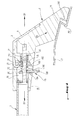
- the device of the invention comprises essentially a rod 3, a lever 4, mounted movable by compared to the housing 2, a drive pawl 5, a retaining pawl 6, and prestressed springs 71 and 72, respectively associated with the drive pawls and restraint.
- the lever 4 is for example rotatably mounted on the case 2, and carries an eccentric 41 via which this lever actuates the drive pawl 5, on which it presses at an articulated support point 51 distant from rod 3.
- Training and retaining pawls 5 and 6 for example have respective holes 50 and 60, by which these pawls are threaded on the rod 3.
- the holes 50 and 60 have a size such that, when the pawls 5 and 6 are perpendicular to the rod 3, this rod slides freely in these holes, whereas, when the pawls 5 and 6 are sufficiently inclined with respect to the rod 3, the holes are supported cantilevered on rod 3 and block the movement of this rod in at least one of the directions D1 and D2.
- each of the pawls 5 and 6 can adopt, with respect to the rod 3, a configuration pass in which the rod 3 slides freely by report to this ratchet, and a blocking configuration in which rod 3 is blocked in translation relative to at this ratchet in at least one of the directions longitudinal D1 and D2.
- the holes 50 and 60 may have rectilinear edges, and the rod 3 can have a polygonal section, for example the shaped like a regular hexagon.
- the spring 72 continuously stresses the pawl of retainer 6 towards its blocking configuration, in one direction suitable for blocking the sliding of the rod 3 according to the direction D2.
- the spring 72 is compressed between a fixed stop 83 of the housing 20 and the retaining pawl 6, that it requests at a distance from this stop 83 according to the direction D2, while the retaining pawl 6 crosses a bore 200 of the housing 2 and is mounted tilting around of a stop 84 of this housing.
- This tilting can be obtained by pressing exercised by an operator on the external part 61 of this pawl 6, or possibly by pulling rod 3 that performs the pawl drive 5 in the direction D1, as will be understood below.
- the drive pawl 5 is permanently biased towards its passing configuration by the spring 71, the latter being compressed between a fixed stop 81 of the housing 20 and the drive pawl 5.
- This pawl 5 is placed in its configuration blocking by movement of lever 4, actuated against the force exerted by the spring 71.
- the lever 4 is movable, relative to the housing 2, between a position initial (figure 1) and a final position (figure 3), in passing through a hooking position (figure 2).
- lever 4 When lever 4 is in its position hooking (figure 2), it switches the ratchet drive 5 relative to the rod, so that ratchet adopts its blocking configuration.
- the pawl drive 5 In the final position of lever 4, the pawl drive 5 is therefore in a position offset from its rest position in direction D1, i.e. that it is released from the second fixed stop 82, and that it further compresses the spring 71 towards the fixed stop 8.
- the rod 3 is therefore globally displaced in direction D1 with respect to the position it occupied before the actuation of the lever 4, that is to say relative to the position illustrated in figure 1.
Landscapes
- Engineering & Computer Science (AREA)
- Mechanical Engineering (AREA)
- Fittings On The Vehicle Exterior For Carrying Loads, And Devices For Holding Or Mounting Articles (AREA)
Abstract
Description
- la Figure 1 est une vue en coupe d'un dispositif conforme à l'invention, représenté en extension, et dans lequel le levier est en position initiale;
- la Figure 2 est une vue en coupe du dispositif de la figure 1, le levier étant représenté en position d'accrochage;
- la Figure 3 est une vue en coupe du dispositif de la figure 1 représenté après serrage, le levier étant en position finale;
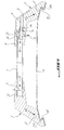
- la Figure 4 est une vue en coupe du dispositif de la figure 1 représenté après serrage, le levier ayant été ramené à sa position initiale; et
- la Figure 5 est une vue en coupe à échelle réduite d'un dispositif conforme à l'invention, fixé au pavillon d'un véhicule automobile.
Claims (11)
- Dispositif télescopique réglable, comprenant une barre (1) coulissante suivant des première et seconde directions longitudinales (D1, D2) opposées l'une à l'autre, et un boítier (2) présentant un logement (20) dans lequel une extrémité (10) de la barre (1) est reçue à coulissement contrôlé, caractérisé en ce qu'il comprend une tige (3), un levier (4) mobile par rapport au boítier (2), des cliquets d'entraínement et de retenue (5, 6), et des premier et second ressorts précontraints (71, 72), en ce que la tige (3) fait saillie de l'extrémité (10) de la barre (1) et est engagée dans le logement (20) du boítier (2) suivant la première direction longitudinale (D1), en ce que chaque cliquet (5, 6) adopte par rapport à la tige (3) une configuration passante, dans laquelle la tige (3) coulisse librement par rapport à ce cliquet (5, 6), et une configuration bloquante, dans laquelle la tige (3) est bloquée en translation par rapport à ce cliquet (5, 6) dans l'une au moins des première et seconde directions longitudinales (D1, D2), en ce que le premier ressort (71) sollicite le cliquet d'entraínement (5) vers sa configuration passante, en ce que le second ressort (72) sollicite le cliquet de retenue (6) vers sa configuration bloquante pour un coulissement de la tige (3) suivant la seconde direction (D2), en ce que le cliquet d'entraínement (5) est sélectivement placé dans sa configuration bloquante par le levier (4) agissant à l'encontre du premier ressort (71), et en ce que le cliquet d'entraínement (5) est sélectivement déplacé par le levier (4), en configuration bloquante, dans la première direction (D1) par rapport au boítier (2).
- Dispositif télescopique réglable suivant la revendication 1, caractérisé en ce que chacun des cliquets d'entraínement et de retenue (5, 6) présente un perçage (50, 60) enfilé sur la tige (3).
- Dispositif télescopique réglable suivant la revendication 1 ou 2, caractérisé en ce que chaque cliquet (5, 6) adopte, en configuration passante, une orientation sensiblement perpendiculaire à la tige (3) et, en configuration bloquante, une orientation inclinée par rapport à la tige (3) dans laquelle ce cliquet (5, 6) s'appuie en porte-à-faux sur la tige (3).
- Dispositif télescopique réglable suivant l'une quelconque des revendications précédentes, caractérisé en ce que le levier (4) est mobile par rapport au boítier (2) entre une position initiale et une position finale en passant par une position d'accrochage, en ce que le premier ressort (71) est comprimé entre une première butée fixe (81) du logement (20) et le cliquet d'entraínement (5), en ce que le levier (4) appuie sélectivement sur le cliquet d'entraínement (5) en un point d'appui articulé (51) distant de la tige (3), en ce que le cliquet d'entraínement (5), dans la position initiale du levier (4), est sollicité par le premier ressort précontraint (71), suivant la seconde direction longitudinale (D2), contre une seconde butée fixe (82) du logement (20), et adopte une position de repos dans laquelle il est en configuration passante, en ce que le cliquet d'entraínement (5), dans la position d'accrochage du levier (4), est placé par ce levier (4) dans sa configuration bloquante, en ce que le cliquet d'entraínement (5), dans la position finale du levier (4), adopte une position décalée de sa position de repos suivant la première direction longitudinale (D1) dans laquelle il est dégagé de la seconde butée fixe (82), et dans laquelle il comprime davantage le premier ressort précontraint (71) vers la première butée fixe (81), en ce que le second ressort (72) est comprimé entre une troisième butée fixe (83) du logement (20) et le cliquet de retenue (6), qu'il sollicite à distance de la troisième butée fixe (83), et en ce que le cliquet de retenue (6) est monté basculant, par rapport au boítier (2) et à la tige (3), entre sa configuration bloquante et sa configuration passante, ce cliquet de retenue (6) étant sollicité vers sa configuration bloquante par le second ressort précontraint (72) suivant la seconde direction (D2), et vers sa position passante par un basculement de ce cliquet de retenue (6) dans la première direction (D1).
- Dispositif télescopique réglable suivant l'une quelconque des revendications précédentes, caractérisé en ce que le levier (4) est mobile en rotation par rapport au boítier (2) et porte un excentrique (41) par l'intermédiaire duquel il actionne le cliquet d'entraínement (5).
- Dispositif télescopique selon l'une des revendications précédentes, caractérisé en ce que le cliquet de retenue (6) comprend une partie externe (61) traversant un perçage (200) du boítier (2) et sur laquelle un opérateur peut exercer une pression pour basculer le cliquet de retenue (6) à sa position passante.
- Dispositif télescopique réglable suivant l'une quelconque des revendications précédentes, caractérisé en ce que le boítier (2) présente un pied (21) qui s'étend suivant une direction (D3) inclinée par rapport à la première direction (D1).
- Dispositif télescopique réglable suivant la revendication 7, caractérisé en ce qu'il comprend un boítier (2, 2') à chaque extrémité (10, 10') de la barre (1), et en ce que chaque boítier (2, 2') comporte un pied (21) s'étendant suivant une direction (D3, D3') inclinée par rapport à la première direction (D1) et présentant un relief d'accrochage (210, 210').
- Dispositif télescopique selon la revendication 8, caractérisé en ce que le boítier (2') opposé au boítier (2) comportant les cliquets d'entraínement et de retenue (5, 6) est fixé à la barre (1) au moyen d'une cheville (11).
- Dispositif télescopique selon l'une des revendications précédentes caractérisé en ce que le levier mobile (4), en configuration passante du cliquet d'entraínement (5), est logé dans le boítier (2).
- Application d'un dispositif télescopique réglable suivant l'une des revendications 8 à 10 à la fixation de la barre sur le pavillon (9) d'un véhicule automobile, dans laquelle le pavillon (9) présente des reliefs de retenue (90, 90'), et dans laquelle la barre (1) est ajustée en coulissement dans l'un des boítiers (2, 2') jusqu'à ce que les reliefs d'accrochage (210, 210') du dispositif télescopique enserrent les reliefs de retenue (90, 90') du pavillon (9).
Applications Claiming Priority (2)
| Application Number | Priority Date | Filing Date | Title |
|---|---|---|---|
| FR0109543 | 2001-07-17 | ||
| FR0109543A FR2827558B1 (fr) | 2001-07-17 | 2001-07-17 | Dispositif telescopique reglable a barre, et application a la fixation de la barre sur le pavillon d'un vehicule automobile |
Publications (1)
| Publication Number | Publication Date |
|---|---|
| EP1277619A1 true EP1277619A1 (fr) | 2003-01-22 |
Family
ID=8865615
Family Applications (1)
| Application Number | Title | Priority Date | Filing Date |
|---|---|---|---|
| EP02291789A Withdrawn EP1277619A1 (fr) | 2001-07-17 | 2002-07-16 | Dispositif téléscopique réglable à cliquet, et application sur gallerie de toit de véhicule |
Country Status (2)
| Country | Link |
|---|---|
| EP (1) | EP1277619A1 (fr) |
| FR (1) | FR2827558B1 (fr) |
Cited By (1)
| Publication number | Priority date | Publication date | Assignee | Title |
|---|---|---|---|---|
| WO2011078697A1 (fr) * | 2009-12-01 | 2011-06-30 | Hubco Automotive Limited | Ensemble de pied |
Citations (7)
| Publication number | Priority date | Publication date | Assignee | Title |
|---|---|---|---|---|
| US2239268A (en) * | 1939-12-14 | 1941-04-22 | Auto Specialties Mfg Co | Lifting jack |
| US2534857A (en) * | 1949-08-30 | 1950-12-19 | Crewe Mfg & Tool Co | Ratchet mechanism for calking guns |
| US5148067A (en) * | 1991-07-01 | 1992-09-15 | Lasota Laurence | Latching linear motor |
| DE4141826A1 (de) * | 1991-12-18 | 1993-06-24 | Friedhelm Schneider | Entleerungsvorrichtung fuer kartuschen und behaelter mit hochviskosem inhalt |
| US5735410A (en) * | 1996-09-12 | 1998-04-07 | Kallstrom; Ervin C. | Stand for vehicle wheel |
| US5823403A (en) * | 1996-01-17 | 1998-10-20 | Albion Engineering Company | High thrust drive system and devices employing |
| EP1247998A1 (fr) * | 2001-04-05 | 2002-10-09 | Sinto Auto | Assemblage mécanique réglable, et application |
-
2001
- 2001-07-17 FR FR0109543A patent/FR2827558B1/fr not_active Expired - Fee Related
-
2002
- 2002-07-16 EP EP02291789A patent/EP1277619A1/fr not_active Withdrawn
Patent Citations (7)
| Publication number | Priority date | Publication date | Assignee | Title |
|---|---|---|---|---|
| US2239268A (en) * | 1939-12-14 | 1941-04-22 | Auto Specialties Mfg Co | Lifting jack |
| US2534857A (en) * | 1949-08-30 | 1950-12-19 | Crewe Mfg & Tool Co | Ratchet mechanism for calking guns |
| US5148067A (en) * | 1991-07-01 | 1992-09-15 | Lasota Laurence | Latching linear motor |
| DE4141826A1 (de) * | 1991-12-18 | 1993-06-24 | Friedhelm Schneider | Entleerungsvorrichtung fuer kartuschen und behaelter mit hochviskosem inhalt |
| US5823403A (en) * | 1996-01-17 | 1998-10-20 | Albion Engineering Company | High thrust drive system and devices employing |
| US5735410A (en) * | 1996-09-12 | 1998-04-07 | Kallstrom; Ervin C. | Stand for vehicle wheel |
| EP1247998A1 (fr) * | 2001-04-05 | 2002-10-09 | Sinto Auto | Assemblage mécanique réglable, et application |
Cited By (3)
| Publication number | Priority date | Publication date | Assignee | Title |
|---|---|---|---|---|
| WO2011078697A1 (fr) * | 2009-12-01 | 2011-06-30 | Hubco Automotive Limited | Ensemble de pied |
| CN102834299A (zh) * | 2009-12-01 | 2012-12-19 | 胡布科汽车有限公司 | 支腿组件 |
| AU2010335063B2 (en) * | 2009-12-01 | 2014-05-29 | Yakima Australia Pty Limited | Leg assembly |
Also Published As
| Publication number | Publication date |
|---|---|
| FR2827558A1 (fr) | 2003-01-24 |
| FR2827558B1 (fr) | 2003-10-31 |
Similar Documents
| Publication | Publication Date | Title |
|---|---|---|
| EP2432954B1 (fr) | Poignee d'un ouvrant de vehicule automobile | |
| US4854187A (en) | Hand brake assembly for a vehicle | |
| FR2562003A1 (fr) | Dispositif de reglage d'un coussin d'assise de siege, notamment dans un vehicule automobile | |
| FR2530205A1 (fr) | Dispositif retroviseur de porte pour automobiles | |
| FR2693535A1 (fr) | Dispositif de sécurité pour lève-vitre électriques de véhicule à câble. | |
| EP2572759A1 (fr) | Dispositif de protection contre la chute | |
| EP0579518B1 (fr) | Lève-vitre électrique de véhicule du type à câble coulissant le long d'un rail de guidage | |
| EP1277619A1 (fr) | Dispositif téléscopique réglable à cliquet, et application sur gallerie de toit de véhicule | |
| FR2775226A1 (fr) | Dispositif de reglage de la course de selection d'un levier de vitesse de vehicule automobile entre le point mort et le couloir de vitesses 1-2 | |
| EP1072735B1 (fr) | Dispositif d'assistance à la pose de lambris | |
| EP1702795B1 (fr) | Système de fixation d'un projecteur sur un bouclier de véhicule routier et procédé d'installation et de fixation du projecteur sur le bouclier | |
| FR2697566A1 (fr) | Serrure à pêne basculant. | |
| FR2791011A1 (fr) | Dispositif de montage d'un ecran de projection ou d'affichage d'informations pour vehicules automobiles | |
| FR2853293A1 (fr) | Dispositif de commande de frein de service | |
| FR3074780A1 (fr) | Dispositif pour une commande manuelle d'urgence d'un systeme distant | |
| FR2818303A1 (fr) | Serrure anti-panique adaptable | |
| JP4395487B2 (ja) | 可倒式パーキングブレーキ装置 | |
| EP1449730A1 (fr) | Dispositif de commande manuelle de frein de parking | |
| FR2469312A1 (fr) | Butee escamotable pour accelerateur de vehicule | |
| EP1247998A1 (fr) | Assemblage mécanique réglable, et application | |
| FR2889141A1 (fr) | Dispositif antivol permettant de commander le verrouillage d'une colonne de direction d'un vehicule automobile | |
| EP1351835A1 (fr) | Dispositif de commandes au volant pour vehicule | |
| FR2535805A1 (fr) | Dispositif de rattrapage de jeu a cliquet pour frein a tambour de vehicule automobile | |
| FR2725752A1 (fr) | Dispositif de blocage de bras actionneur commande par un systeme mecanique a mouvement lineaire et comprenant une protection contre les chocs et les efforts mecaniques | |
| FR2932125A1 (fr) | Dispositif de manoeuvre d'un couvercle de coffre |
Legal Events
| Date | Code | Title | Description |
|---|---|---|---|
| PUAI | Public reference made under article 153(3) epc to a published international application that has entered the european phase |
Free format text: ORIGINAL CODE: 0009012 |
|
| AK | Designated contracting states |
Kind code of ref document: A1 Designated state(s): AT BE BG CH CY CZ DE DK EE ES FI FR GB GR IE IT LI LU MC NL PT SE SK TR |
|
| AX | Request for extension of the european patent |
Free format text: AL;LT;LV;MK;RO;SI |
|
| 17P | Request for examination filed |
Effective date: 20030716 |
|
| AKX | Designation fees paid |
Designated state(s): AT BE BG CH CY CZ DE DK EE ES FI FR GB GR IE IT LI LU MC NL PT SE SK TR |
|
| 17Q | First examination report despatched |
Effective date: 20040819 |
|
| RAP1 | Party data changed (applicant data changed or rights of an application transferred) |
Owner name: AUTOMAXI INTERNATIONAL |
|
| GRAP | Despatch of communication of intention to grant a patent |
Free format text: ORIGINAL CODE: EPIDOSNIGR1 |
|
| STAA | Information on the status of an ep patent application or granted ep patent |
Free format text: STATUS: THE APPLICATION IS DEEMED TO BE WITHDRAWN |
|
| 18D | Application deemed to be withdrawn |
Effective date: 20070619 |