EP1277565A2 - Presseneinrichtung zum Herstellen masshaltiger Presslinge aus pulverförmigem Material - Google Patents
Presseneinrichtung zum Herstellen masshaltiger Presslinge aus pulverförmigem Material Download PDFInfo
- Publication number
- EP1277565A2 EP1277565A2 EP02016227A EP02016227A EP1277565A2 EP 1277565 A2 EP1277565 A2 EP 1277565A2 EP 02016227 A EP02016227 A EP 02016227A EP 02016227 A EP02016227 A EP 02016227A EP 1277565 A2 EP1277565 A2 EP 1277565A2
- Authority
- EP
- European Patent Office
- Prior art keywords
- stamp
- press
- base body
- carrier
- framework
- Prior art date
- Legal status (The legal status is an assumption and is not a legal conclusion. Google has not performed a legal analysis and makes no representation as to the accuracy of the status listed.)
- Withdrawn
Links
Images


Classifications
-
- B—PERFORMING OPERATIONS; TRANSPORTING
- B30—PRESSES
- B30B—PRESSES IN GENERAL
- B30B11/00—Presses specially adapted for forming shaped articles from material in particulate or plastic state, e.g. briquetting presses, tabletting presses
- B30B11/02—Presses specially adapted for forming shaped articles from material in particulate or plastic state, e.g. briquetting presses, tabletting presses using a ram exerting pressure on the material in a moulding space
-
- B—PERFORMING OPERATIONS; TRANSPORTING
- B30—PRESSES
- B30B—PRESSES IN GENERAL
- B30B11/00—Presses specially adapted for forming shaped articles from material in particulate or plastic state, e.g. briquetting presses, tabletting presses
- B30B11/005—Control arrangements
Definitions
- the invention relates to a press device for Pressing true-to-size compacts from one essentially powdery material with the generic features of claim 1.
- Such presses are generally used for pressing powder or granules made of iron, basic ceramic components or the like into pellets, for. B. gears or molded parts. Due to the high specific pressures of 30 - 100 kN / cm 2 and more, a very high stability of the press device is required.
- a modular press is known from DE 31 42 126 C2 from the actual press to apply the Main pressing force and a press device, which can be inserted into the actual press as an adapter can.
- the press device that can be used consists of a Tool rack that has an upper and a lower Connection device between the two press bears Press is coupled.
- adapter-like press device from a framework from pull rods used to guide a variety of plates, Stamp carriers and a die plate between the also arranged or stored on the framework Connection facilities exist.
- a base plate in which hydraulic devices for relative movement of individuals trained as stamp carriers Panels are arranged with a bearing approach in the actual press stored.
- the other plates are movable in the framework relative to this base plate stored.
- the die holding plate is over the framework with the lower connecting device of the adapter rigid connected and opposite the upper connecting device of the Adapters slidably arranged in the framework.
- the single ones Stamp carriers are hydraulic compared to the base plate movable so that it is between a filling position in which the Die opening of the die holder plate can be filled with powder and a final press position, in which the powder with the help is pressed from press dies to a compact, are movable.
- the stamps for pressing the powder sit on the respective stamp carriers. Are in the press end position the individual stamp carriers are supported on fixed stops.
- Both the piston / cylinder devices for hydraulic Driving the individual stamp carriers as well Fixed stops are from the respective central openings of the individual stamp carrier spaced in the edge area of the Stamp carrier arranged.
- the central openings formed in the individual stamp carriers such that each the stamp on one of the die holding plate sit on the distant stamp carrier by the openings of the closer to the die holding plate located stamp plates can be passed.
- stamp carrier To improve the leadership of the stamp carrier is from DE 40 00 423 C2 a press for the production of dimensionally stable press
- the upper and lower press bears and an adapter into the press inserted tool frame, which has a lower Coupling plate on the lower bear and over an upper one Connector on the upper bear is connectable.
- On one in the Press firmly supported base plate of the tool frame is a movably supported framework made of tie rods provided which the lower clutch plate with a Rigidly connect the die holding plate.
- stamp carrier On one in the Press firmly supported base plate of the tool frame is a movably supported framework made of tie rods provided which the lower clutch plate with a Rigidly connect the die holding plate.
- stamp carrier Furthermore, from the Base plate made by piston / cylinder drives stamp carrier movable into the filling and pressing positions.
- the stamp carrier for improvement the leadership is suggested to use the stamp carrier as pots form, which on cylindrical surfaces relative to Base plate are guided. Also lie with this arrangement the stamp carrier in the press end
- the object of the invention is to provide a press Manufacture dimensionally stable compacts from essentially to improve powdery material so that also for stamp carrier arranged away from the base plate Deflection in the press end position is reduced.
- This task is carried out by a press device Manufacture dimensionally stable compacts with the characteristics of Claim 1 or by methods of manufacturing dimensionally stable compacts with the features of the claims 14 and 15 solved.
- the central support of the stamp carrier enables in the Press end position a power transmission such that the Do not bend the stamp carrier anymore.
- the line of force will the same or at least essentially the same in extension of the support devices or fixed stops by the corresponding sections of the stamp carrier more or less straight on the stamp with which powder or Granules are pressed in the die opening.
- central stores also offer Fixed stops or support devices are sufficient Stability to support the individual stamp carriers in the Pressing end.
- two are insufficient dimensioned support devices for supporting above lying stamp carrier with above, also laterally above the support device arranged stamps to a good to allow central power distribution.
- the support devices are thus the central one Passage opening of a stamp carrier adjacent arranged.
- the openings for the support devices appropriately trained in lower stamp carriers become. Enlarged openings for Stamps of deeper levels, center pens and the same too for carrying out support devices in their edge area be used. The narrower the opening areas to Carrying out the support devices in the stamp carriers are trained, the more stability is for the individual stamp carrier offered. Conversely enable wider openings for the passage of the support devices performing a variety of supports and especially the optional use of several Supporting devices for the first pressing tests. Is possible but also the provision of separate openings for Carrying out support devices by one Stamp carrier through. Such openings are for one Stamp carrier less in terms of its stability disadvantageous and also offer when carried out or used fixed stop or used Support device for guiding the stamp carrier with the Opening up further support.
- stamp carriers with only small stamps on their surface can also be used to put on the Stamps and reach under by support devices only accordingly small dimensioned attachment devices in protrude into the central opening of the stamp carrier to let.
- the Hydraulic devices in extension of the Attachments from the center of the central opening arranged.
- a press device for pressing dimensionally stable compacts from powdered or granular material, in particular made of iron powder Ceramic powder or the like from a variety of Assemblies.
- This is essentially a lower one Press block, which by a base plate 0, stamp carrier 1, 2, 3 and 4, a die holding plate 5 and a lower one Connection device 71 is formed, and an upper Press block 6, one above the other in a framework Drawbars 70 and the like are arranged.
- the upper press block 6 preferably comparable assemblies have as the lower press block.
- the upper press block 6 can e.g. through an upper connector 72, a upper base plate and stamp carrier are formed.
- the lower connecting device 71 has one Coupling device for coupling to a lower one Press bears on a hydraulic press or the like.
- the upper press block 6 has a corresponding upper one Connection device 72 with a coupling device for Connect to an upper press bear.
- guide rods 73 For connecting the lower press block and the upper one Press block 6 are shown guide rods 73, which in Extension of the tie rods 70 of the framework arranged are.
- the framework thus holds the entire individual Components of the adapter 7 together.
- Guide rods 73 between the two press blocks are not absolutely necessary.
- the lower connection device 71 After installing the press device or adapter 7 in a press is the lower connection device 71 with the lower press bears coupled to the press.
- the top view of which can also be seen from FIG. 2 is arranged.
- the base plate has 0 a rectangular outer circumference, with the four tie rods 70 through corresponding openings in their corner areas to lead.
- the base plate 0 has one on two sides Storage approach 51 with which the base plate 0 after Installation firmly connected to the press, at least in this is firmly supported.
- the base plate 0 serves as a storage facility for the large number of stamp carriers 1 - 4, which here essentially as plate-shaped components are shown.
- the single ones Stamp holders 1 - 4 are hydraulic Devices movable relative to the base plate 0. Farther lead from the base plate 0 from fixed stops 12, 22, 32, 42 in the direction of the individual stamp carriers 1 - 4, the Stamp carrier 1 - 4 in the final press position on this correspondingly assigned to the fixed stops 12, 22, 32 or 42 rest.
- the fixed stops 12, 22, 42 are seated preferably on contact surfaces 57-59.
- the inside for example radially evenly around a central press axis 74 arranged stamp carrier 3rd arranged centrally on or in the base plate 0.
- a piston / cylinder arrangement 33 to move the inner one Stamp carrier 3 relative to the base plate 0 is in the area a central through opening 54 through the base plate 0 arranged through. This causes a pressurized Displacement of the internal stamp carrier 3 in Direction of the central press axis 74 allows.
- the piston rod 35 of the piston / cylinder assembly 33 for the most internal Stamp carrier 3 has a central opening 34 through which a Center pin or other assemblies towards the central one Press axis 74 through the innermost punch carrier 3 can be passed through.
- the inner one Stamp carrier 3 is adjacent to a first stamp carrier 1 arranged. While the inside stamp carrier 3 at this embodiment entirely from the base plate 0 is stored and managed, also here in Top view square first stamp carrier, as well 3 shows holes in its corner areas, through which the four tie rods 70 of the framework round lead. This is used to store the first Stamp carrier 1 such that it only in the direction of central press axis 74 is slidably disposed. To the Moving the first stamp carrier 1 in the direction of the central one Press axis 74 are one or more piston / cylinder assemblies 13, here two diametrically opposite, in the Base plate 0 arranged. Alternatively, the piston / cylinder arrangements e.g.
- the one or more fixed stops 12 for supporting the first Stamp carrier 1 in the press end position are on the Base plate 0 directly the opening and Guide device for the inside stamp carrier 3 arranged adjacent.
- the one or more fixed stops 12 for the first stamp carrier 1 are thus in the press end position below the area of the inside of the opening 14 Stamp carrier 1 and are therefore in the effective direction of Force line of the press force.
- attachment device 16 for stamps of the first Stamp holder 1 outlined.
- This insert or attachment device 16 for stamp protrudes into the opening 14 of the first Stamp holder 1 into it.
- the width of the attachment device 16 is sufficient for the stamps applied To give support and also to be safe on the fixed stops 12 to sit for the first stamp carrier 1.
- the opening 14 of the first stamp carrier 1 thus consists of a first central opening section through which on the internal stamp carrier 3 attached stamps can be passed and an outer annular Section 14a, through the fixed stops to support others Pass the stamp carriers 2, 4 of higher-level assemblies through.
- additional or narrower or wider fixed stops 12 or attachment devices 16 for the first stamp carrier 1 are formed.
- the next press section is the present one Embodiment of the second stamp carrier 2, which in Fig. 1st is arranged above the first stamp carrier 1.
- Fig. 4 shows the structure with regard to this second stamp carrier 2 essentially comparable to that of the first stamp carrier 1.
- the second stamp carrier 2 is also performed on the four tie rods 70 through make appropriate openings in its outer peripheral area.
- the second punch carrier 2 is for lifting or lowering also with a piston rod 25 of a piston / cylinder arrangement 23 for the second stamp carrier 2 connected is arranged in the base plate 0.
- the second stamp carrier 2 a central opening 24 for Passing stamps and the like on the first stamp carrier 1, the inner stamp carrier 3 or as a center pin in the press end position are to be passed through.
- the second stamp carrier 2 is included a height adjustment device 27, wherein a height adjustment device can be used in this regard, as known per se from DE 40 00 423 C2 is.
- a height adjustment device can be used in this regard, as known per se from DE 40 00 423 C2 is.
- This consists of an adjusting ring 27a with a underside of the inclined plane on the Fixed stops 22 for the second stamp carrier 2 rests.
- the attachment device 26 of the second stamp carrier 2 in the present Embodiment from a closed annular Component. This allows stamps to be full accordingly be placed circumferentially on the attachment device 26.
- the fixed stops 22 are in turn on the base plate 0 arranged that they in the direction of action, in particular in Force line of the press force below the stamp under the Grip attachment device 26.
- the arrangement of the Fixed stops 22 are chosen so that they are as possible close to the central opening 24 under the attachment 26 grab.
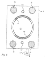
- another is Assembly above the second stamp carrier 2 another, fourth stamp carrier 4 arranged, which with respect to the Construction similar to the stamp carriers described above 1, 2 is formed.
- the fourth Stamp carrier 4 in turn through holes for performing the Drawbars 70 on.
- the piston rod 45 To raise or lower the fourth Stamp carrier relative to the base plate 0 are also one or more, here two piston / cylinder arrangements ready provided whose cylinders are arranged in the base plate 0 are, the piston rod 45 through corresponding openings in the base plate 0, the first stamp carrier 1 and the second stamp carrier 2 to fourth stamp carrier 4 lead.
- the fourth stamp carrier 4 also has one central opening 44 on which to carry out the stamp and the same serves from lower-lying stamp carriers.
- the inside of the fourth stamp carrier 4 also designed as an attachment device 46, the Top is designed for placing stamps while the underside for placing the fourth stamp carrier 4 on one or more corresponding fixed stops 42 are formed is.
- the fixed stops 42 are in this way on the base plate 0 arranged that from this through the first and the second stamp carrier 1 or 2 through to the fourth Lead stamp carrier 4 and there below on this attached stamp in the effective direction of the pressing force are arranged.
- the fourth also Stamp carrier 4 a height adjustment device 47 for the same Height adjustment relative to base plate 0.
- Such Height adjustment devices can be used for the different Stamp carrier optionally provided or omitted become.
- the through openings 14a, 24a for performing the Fixed stops 22 and 42 by the first stamp carrier 1 and the second stamp carrier 2 are in the present Embodiment to illustrate the possibility of a Variety of opening arrangements designed differently.
- the attachment devices 16 for stamps of the first Stamp carrier 1 from the sides into the central opening 14 into it, so that ring-shaped in its edge regions Opening extensions 14a are formed, through which corresponding fixed stops 22, 42 are passed can.
- the lateral opening 14a can be stepped decrease in scope.
- the opening for performing Fixed stops 22 for the second stamp carrier 2 therefore larger than the opening for performing fixed stops 42nd for the fourth stamp carrier 4. It is advantageous the base for the arrangement of fixed stops each formed in a ring.
- the second stamp carrier 2 shows another possibility for the arrangement of openings for fixed stops 42 the central opening 24 of a circumferential, annular Attachment device 26, so that several or according to partial round fixed stops 22 the attachment device 26 can reach under.
- To perform the Fixed stops 42 through the second stamp carrier 2 are 26 openings outside the ring-shaped attachment device 24a, which advantageously in one Area below a corresponding attachment device 46 of the fourth stamp carrier 4 are formed. This enables the fixed stops 42 to be arranged Direction of action of the press force also with regard to the stamp on the fourth stamp carrier 4.
- the fourth stamp carrier 4 is the next one Assembly arranged the die holding plate 5, which over the Tie rods 70 rigid with the lower connecting device 71 connected is.
- the die holding plate 5 which over the Tie rods 70 rigid with the lower connecting device 71 connected is.
- the die holding plate 5 In an extension of the die holding plate 5 are above this, e.g. B. via guide rods 73, others Assemblies of the upper press block 6 arranged, wherein this is essentially a mirror image of the one described Structure of the lower press block can be arranged.
- the upper connection device 72 is connected to the Guide rods 73 relative to the die holding plate 5 flexibly guided. But a fixed one is also possible Connection of the guide rods 73 to the die holding plate 5, in which case the entire upper assembly including the upper link 72 relative to the die holding plate 5 via the guide rods 73 is slidably arranged.
- the die 5 is in a first Step relative to the base plate 0 and the stamp carriers 1 - 4 of the lower press block moved up.
- the stamps on the stamp carriers 1 - 4 and optionally also the central pin from the die opening 56 also partly moved upwards, but not so far, like the die so that a die opening 56 is formed into which powder can be poured from above.
- the individual stamp carriers 1 - 4 with the stamps against the die holding plate 5 pressed, the stamp the powder in the Compress die opening 56 into a compact.
- a special feature of the press device are the through assigned fixed stops 12, 22, 32, 42 centrally supported Stamp holder 1 - 4.
- the central support enables in the press end position an exercise of the pressing force in Direction of action, especially the line of force of all individuals Stamp, so that a bending of the individual stamp carrier minimized or completely avoided towards their central opening can be.
- Matrix holding plate with the lower connection device is firmly or rigidly connected and base plate and Stamp carriers are movable relative to it
- can also be another relative arrangement can be chosen.
Landscapes
- Engineering & Computer Science (AREA)
- Mechanical Engineering (AREA)
- Press Drives And Press Lines (AREA)
- Press-Shaping Or Shaping Using Conveyers (AREA)
- Powder Metallurgy (AREA)
Abstract
Description
- Fig. 1
- eine Presseneinrichtung zum Herstellen maßhaltiger Presslinge aus pulverförmigem Material im Querschnitt aus seitlicher Richtung;
- Fig. 2
- eine Draufsicht auf eine Grundplatte dieser Presseneinrichtung mit angedeuteten Auflageflächen für Abstützeinrichtungen;
- Fig. 3
- eine Draufsicht auf einen ersten Stempelträger oberhalb der Grundplatte;
- Fig. 4
- einen zweiten Stempelträger oberhalb des ersten Stempelträgers, wobei beide Durchtrittsöffnungen für Stempel und dergleichen von Stempelträgern tieferer Ebenen aufweisen, und
- Fig. 5
- einen weiteren Stempelträger oberhalb der genannten Stempelträger.
Claims (15)
- Presseneinrichtung zum Herstellen maßhaltiger Presslinge aus im wesentlichen pulverförmigem Material, insbesondere Eisenpulver oder Keramikpulver, mitdadurch gekennzeichnet,einem Rahmenwerk (70, 73), welches über eine untere Verbindungseinrichtung (71) mit einem Unterbären einer Presse und über eine obere Verbindungseinrichtung (72) mit einem Oberbären der Presse adaptermäßig verbindbar ist,einer Matrizenhalteplatte (5), die im Rahmenwerk (70, 73) angeordnet ist,einem Grundkörper (0), der in dem Rahmenwerk (70, 73) angeordnet ist, wobei die Matrizenhalteplatte (5) und der Grundkörper (0) relativ zueinander verschiebbar in dem Rahmenwerk (70) angeordnet sind,einer Vielzahl von Stempelträgern (1 - 4), von denen zumindest ein Teil am Rahmenwerk (70) relativ zur Matrizenhalteplatte (5) und relativ zum Grundkörper (0) verschiebbar zwischen diesen gelagert ist, wobei die Stempelträger (1 - 4) mittels Kolben-/Zylinder-Antrieben relativ zum Grundkörper (0) in Füll- und Pressstellungen bewegbar sind, undAbstützeinrichtungen (12, 22, 32, 42), welche die Stempelträger (1 - 4) in Pressendstellung relativ zum Grundkörper (0) abstützen,dass die Abstützeinrichtungen (12, 22, 32, 42) zwischen dem Grundkörper (0) und den zugeordneten Stempelträgern (1 - 4) derart angeordnet sind, dass auf den Stempelträgern (1 - 4) sitzende Stempel in Pressendstellung über die Abstützeinrichtungen (12, 22, 32, 42) in Kraftlinie zentral abgestützt sind.
- Presseneinrichtung nach Anspruch 1, bei der einzelne oder alle der Abstützeinrichtungen (22, 42) zu nicht direkt zum Grundkörper (0) benachbarten Stempelträgern (2, 4) jeweils auf oder an einem Stempelträger (1, 2) zwischen diesen Stempelträgern (2, 4) und dem Grundkörper (0) abgestützt sind.
- Presseneinrichtung nach Anspruch 1 oder 2, bei der zumindest ein Teil der Abstützeinrichtungen (12, 22, 32, 42) als Festanschläge auf dem Grundkörper (0) angeordnet ist.
- Presseneinrichtung nach einem vorstehenden Anspruch, bei der einzelnen Stempelträgern (1 - 4) eine Abstützeinrichtung (12, 22, 32, 42) zugeordnet ist, welche einen oder mehrere, vorzugsweise jeweils zwei Festanschläge aufweist.
- Presseneinrichtung nach einem vorstehenden Anspruch, bei der die Abstützeinrichtungen (12, 22, 32, 42) zentral, einer zentralen Öffnung (54, 14, 24, 44) der Stempelträger (1 - 4) benachbart, unterhalb der Stempelträger (1 - 4) angeordnet sind und entsprechende Stempel oberhalb dieser Bereiche auf den entsprechenden Stempelträgern (1 - 4) angeordnet sind.
- Presseneinrichtung nach einem vorstehenden Anspruch, bei der eine zentrale Öffnung (14) zumindest eines der Stempelträger (1) mittig für den Durchtritt von Stempeln und dergleichen und im Randbereich (14a) für den Durchtritt von Abstützeinrichtungen (22, 42) zu Stempelträgern (2, 4) zwischen diesem Stempelträger (1) und der Matrizenhalteplatte (5) ausgebildet ist.
- Presseneinrichtung nach einem vorstehenden Anspruch, bei der zumindest bei einem der Stempelträger (2) eine zentrale Öffnung (24) zum Durchtritt von Stempeln, Abstützeinrichtungen (42) und dergleichen und zusätzlich eine oder mehrere separate Öffnungen (24a) zum Durchtritt von zumindest einer der Abstützeinrichtungen (42) für einen weiteren Stempelträger (4) zwischen diesem Stempelträger (2) und der Matrizenhalteplatte (5) ausgebildet sind.
- Presseneinrichtung nach Anspruch 7, bei der zumindest eine solcher separaten Öffnungen (24a) durch eine Aufsatzeinrichtung (26) zum Aufsetzen von einem oder mehreren Stempeln auf den Stempelträger (2) mit der separaten Öffnung (24a) von der zentralen Öffnung (24) getrennt sind, wobei die Aufsatzeinrichtung (26) vorzugsweise eine Breite gleich der darauf aufsitzenden Stempel aufweist.
- Presseneinrichtung nach einem vorstehenden Anspruch, bei der eine oder mehrere Aufsatzeinrichtungen (16) zum Aufsetzen von Stempeln und zum Untergreifen von Abstützeinrichtungen (12) in eine zentrale Öffnung (14) eines Stempelträgers (1) hineinragen.
- Presseneinrichtung nach einem vorstehenden Anspruch, bei der die Abstützeinrichtungen (12, 22, 32, 42) eine teilweise zylindrische Innen- und/oder Außenwandung aufweisen.
- Presseneinrichtung nach einem vorstehenden Anspruch, bei der die Abstützeinrichtungen (12, 22, 32, 42) hinsichtlich des Querschnittes ähnlich dem Querschnitt darüber angeordneter Stempel ausgebildet sind.
- Presseneinrichtung nach einem vorstehenden Anspruch, bei der Abstützeinrichtungen (12, 22) mit einer zu zumindest zwei Stempelträgern hin abgestuften Höhe ausgebildet sind, wobei ein von der Matrizenhalteplatte (5) entfernterer Stempelträger (1) auf der niedriger abgestuften Oberfläche der Abstützeinrichtung abgestützt wird und der zur Matrizenhalteplatte (5) hin näher angeordnete Stempelträger (2) auf der höheren Oberfläche der Abstützeinrichtung in Pressendstellung abgestützt wird.
- Presseneinrichtung nach einem vorstehenden Anspruch, bei der Stauchungsmesseinrichtungen (80) an den Abstützeinrichtungen (12, 22, 32, 42) und/oder Stempelträgern (1, 2, 3, 4) befestigt sind.
- Verfahren zum Herstellen maßhaltiger Presslinge aus im wesentlichen pulverförmigem Material, insbesondere Eisenpulver oder Keramikpulver, mit einer Presseneinrichtung mitdadurch gekennzeichnet,einem Rahmenwerk (70, 73) zum adaptermäßigen Verbinden eines Unterbären einer Presse über eine untere Verbindungseinrichtung (71) und zum adaptermäßigen Verbinden eines Oberbären der Presse über eine obere Verbindungseinrichtung (72),einer Matrizenhalteplatte (5), die im Rahmenwerk (70, 73) angeordnet ist, und einem Grundkörper (0), der in dem Rahmenwerk (70, 73) angeordnet ist, wobei die Matrizenhalteplatte (5) und der Grundkörper (0) relativ zueinander verschiebbar in dem Rahmenwerk (70) angeordnet sind,einer Vielzahl von Stempelträgern (1 - 4), von denen zumindest ein Teil am Rahmenwerk (70) relativ zur Matrizenhalteplatte (5) und relativ zum Grundkörper (0) verschiebbar zwischen diesen gelagert ist, undAbstützeinrichtungen (12, 22, 32, 42) zum Abstützen der Stempelträger (1 - 4) beim Pressen in Pressendstellung relativ zum Grundkörper (0),wobei die Stempelträger (1 - 4) mittels Kolben-/Zylinder-Antrieben beim Betrieb relativ zum Grundkörper (0) in Fülloder Pressstellungen bewegt werden,dass die Abstützeinrichtungen (12, 22, 32, 42) zwischen dem Grundkörper (0) und den zugeordneten Stempelträgern (1 - 4) derart angeordnet werden, dass auf den Stempelträgern (1 - 4) sitzende Stempel beim Pressen in Pressendstellung über die Abstützeinrichtungen (12, 22, 32, 42) in Kraftlinie zentral abgestützt werden.
- Verfahren zum Herstellen maßhaltiger Presslinge aus im wesentlichen pulverförmigem Material, insbesondere Eisenpulver oder Keramikpulver, mit einer Presseneinrichtung mitdadurch gekennzeichnet,einem Rahmenwerk (70, 73) zum adaptermäßigen Verbinden eines Unterbären einer Presse über eine untere Verbindungseinrichtung (71) und zum adaptermäßigen Verbinden eines Oberbären der Presse über eine obere Verbindungseinrichtung (72),einer Matrizenhalteplatte (5), die im Rahmenwerk (70, 73) angeordnet ist, und einem Grundkörper (0), der in dem Rahmenwerk (70, 73) angeordnet ist, wobei die Matrizenhalteplatte (5) und der Grundkörper (0) relativ zueinander verschiebbar in dem Rahmenwerk (70) angeordnet sind,einer Vielzahl von Stempelträgern (1 - 4), von denen zumindest ein Teil am Rahmenwerk (70) relativ zur Matrizenhalteplatte (5) und relativ zum Grundkörper (0) verschiebbar zwischen diesen gelagert ist,Abstützeinrichtungen (12, 22, 32, 42) zum Abstützen der Stempelträger (1 - 4) beim Pressen in Pressendstellung relativ zum Grundkörper (0) undMesseinrichtungen (80) zum Messen von Stauchungen beim Pressen an den Festanschlägen und/oder den Stempelträgern,wobei die Stempelträger (1 - 4) mittels Kolben-/Zylinder-Antrieben beim Betrieb relativ zum Grundkörper (0) in Fülloder Pressstellungen bewegt werden, undwobei Messwerte der Messeinrichtungen (80) zum Überwachen des Betriebs verwendet werden,dass die Abstützeinrichtungen (12, 22, 32, 42) zwischen dem Grundkörper (0) und den zugeordneten Stempelträgern (1 - 4) derart angeordnet werden, dass auf den Stempelträgern (1 - 4) sitzende Stempel beim Pressen in Pressendstellung über die Abstützeinrichtungen (12, 22, 32, 42) in Kraftlinie zentral abgestützt werden, so dass die Messwerte der Messeinrichtungen (80) tatsächliche Stauchungen beim Pressen darstellen, unddass mit den Messwerten eine Korrektur der Presskraft und/oder der Justierung von Höhenverstelleinrichtungen der einzelnen Stempelträger gesteuert oder geregelt werden.
Applications Claiming Priority (2)
| Application Number | Priority Date | Filing Date | Title |
|---|---|---|---|
| DE10135523A DE10135523C2 (de) | 2001-07-20 | 2001-07-20 | Presseneinrichtung zum Herstellen maßhaltiger Presslinge aus pulverförmigen Metall |
| DE10135523 | 2001-07-20 |
Publications (2)
| Publication Number | Publication Date |
|---|---|
| EP1277565A2 true EP1277565A2 (de) | 2003-01-22 |
| EP1277565A3 EP1277565A3 (de) | 2004-01-14 |
Family
ID=7692584
Family Applications (1)
| Application Number | Title | Priority Date | Filing Date |
|---|---|---|---|
| EP02016227A Withdrawn EP1277565A3 (de) | 2001-07-20 | 2002-07-19 | Presseneinrichtung zum Herstellen masshaltiger Presslinge aus pulverförmigem Material |
Country Status (3)
| Country | Link |
|---|---|
| US (1) | US6902698B2 (de) |
| EP (1) | EP1277565A3 (de) |
| DE (1) | DE10135523C2 (de) |
Families Citing this family (13)
| Publication number | Priority date | Publication date | Assignee | Title |
|---|---|---|---|---|
| DE10254656B4 (de) * | 2002-11-22 | 2005-10-13 | Dorst Technologies Gmbh & Co. Kg | Presseneinrichtung zum Herstellen maßhaltiger Presslinge mit zentraler Stempelabstützung |
| DE10355963A1 (de) * | 2002-12-02 | 2004-06-24 | Mold-Masters Limited, Georgetown | Hubbegrenzer für einen Nadelventilbetätigungsmechanismus |
| US20050252121A1 (en) * | 2003-02-05 | 2005-11-17 | Richard Hahn | Crown molding with improved mounting surfaces |
| AT502360B1 (de) * | 2004-11-17 | 2007-05-15 | Mpt Metal Press Tec Gmbh | Presse zum herstellen eines gestuften formkörpers aus pulver |
| KR101476855B1 (ko) * | 2006-03-22 | 2014-12-24 | 쓰리엠 이노베이티브 프로퍼티즈 컴파니 | 필터 매체 |
| DE102009049847A1 (de) | 2009-10-19 | 2011-04-21 | Dorst Technologies Gmbh & Co. Kg | Metall- oder Keramikpulver-Presse und Steuerverfahren dafür |
| DE102009049845A1 (de) | 2009-10-19 | 2011-04-21 | Dorst Technologies Gmbh & Co. Kg | Metall- oder Keramikpulver-Presse und Steuerverfahren dafür |
| DE102010033997A1 (de) | 2010-08-11 | 2012-02-16 | Dorst Technologies Gmbh & Co. Kg | Metall- oder Keramikpulver-Elektropresse und Steuerverfahren dafür |
| DE102010033998A1 (de) | 2010-08-11 | 2012-02-16 | Dorst Technologies Gmbh & Co. Kg | Metall- oder Keramikpulver-Elektropresse und Steuerverfahren dafür |
| DE102010044740A1 (de) | 2010-09-08 | 2012-03-08 | Dorst Technologies Gmbh & Co. Kg | Metall- oder Keramikpulver-Elektropresse oder Pressenwerkzeug einer solchen Presse |
| DE102010044688A1 (de) | 2010-09-08 | 2012-03-08 | Dorst Technologies Gmbh & Co. Kg | Metall- oder Keramikpulver-Elektropresse und Steuerverfahren dafür |
| US8733048B1 (en) * | 2013-12-20 | 2014-05-27 | Highland Technologies, LLC | Multi-story durable wall construction |
| DE102014003726A1 (de) | 2014-03-18 | 2015-09-24 | Gkn Sinter Metals Engineering Gmbh | Presse zum Herstellen maßhaltiger Grünlinge und Verfahren zum Herstellen |
Family Cites Families (4)
| Publication number | Priority date | Publication date | Assignee | Title |
|---|---|---|---|---|
| IT1107475B (it) * | 1978-07-24 | 1985-11-25 | Merisinter Spa | Complesso di pressa e porta-stampo per la compattazione nella metallurgia delle polveri |
| DE3142126A1 (de) * | 1981-10-23 | 1983-05-11 | Dorst-Keramikmaschinen-Bau Otto Dorst U. Dipl.-Ing. Walter Schlegel, 8113 Kochel | "presse zum herstellen masshaltiger presslinge aus pulverfoermigem material" |
| DE3919821C2 (de) * | 1989-06-15 | 1994-04-07 | Mannesmann Ag | Verfahren und Vorrichtung zum Herstellen von maßhaltigen Preßlingen |
| DE4000423C2 (de) | 1990-01-09 | 1998-10-08 | Dorst Masch & Anlagen | Presse zur Herstellung maßhaltiger Preßlinge aus pulverförmigem Material |
-
2001
- 2001-07-20 DE DE10135523A patent/DE10135523C2/de not_active Revoked
-
2002
- 2002-07-19 EP EP02016227A patent/EP1277565A3/de not_active Withdrawn
- 2002-07-19 US US10/197,823 patent/US6902698B2/en not_active Expired - Lifetime
Also Published As
| Publication number | Publication date |
|---|---|
| DE10135523C2 (de) | 2003-07-31 |
| US6902698B2 (en) | 2005-06-07 |
| DE10135523A1 (de) | 2003-02-06 |
| EP1277565A3 (de) | 2004-01-14 |
| US20030015813A1 (en) | 2003-01-23 |
Similar Documents
| Publication | Publication Date | Title |
|---|---|---|
| DE3142126C2 (de) | ||
| DE102011116552B4 (de) | Presse | |
| DE10135523C2 (de) | Presseneinrichtung zum Herstellen maßhaltiger Presslinge aus pulverförmigen Metall | |
| DE102010051513A1 (de) | Keramikpulver- und/oder Metallpulver-Pressenwerkzeug, Keramikpulver- und/oder Metallpulver-Presse, modulares System mit einem solchen Pressenwerkzeug, Verfahren zum Zusammensetzen eines solchen Pressenwerkzeugs | |
| DE10254656B4 (de) | Presseneinrichtung zum Herstellen maßhaltiger Presslinge mit zentraler Stempelabstützung | |
| EP2768662B1 (de) | Presse | |
| DE4112839C1 (de) | ||
| DE4022951A1 (de) | Biegerichtmaschine fuer lange profilabschnitte | |
| EP3160726B1 (de) | Verbesserte c-gestell-presse | |
| DE1932393C3 (de) | Verfahren zum Anheben von schweren flächigen Bauteilen sowie Vorrichtung zur Durchfuhrung des Verfahrens | |
| DE4112656A1 (de) | Zieheinrichtung in einer presse zum ziehen von blechformteilen | |
| EP0589240B1 (de) | Liegende Metallstrangpresse | |
| DE102021002385A1 (de) | Werkstückspannelement | |
| DE3434470C2 (de) | Biegepresse | |
| EP0370956B1 (de) | Verfahren und Vorrichtung zum Biegen von Blechstücken | |
| DE3926854C2 (de) | Vorrichtung in Keramik-Pressen zum Füllen der Preßform mit pulverförmigem Preßgut | |
| DE112005001153T5 (de) | Elektrodensäule | |
| DE3002039A1 (de) | Stehende hydraulische gesenkpresse | |
| EP0561159B1 (de) | Vorrichtung zum Pressen von Formteilen aus einer feinkörnigen Masse | |
| DE20122762U1 (de) | Presseneinrichtung zum Herstellen maßhaltiger Presslinge aus pulverförmigem Material | |
| DE19607257C2 (de) | Hydraulische Blechformpresse | |
| DE4315464A1 (de) | Vorrichtung zum Pressen eines vorzugsweise quaderförmigen Preßlings | |
| DE10152114A1 (de) | Pressenanordnung, insbesondere zum Pressen von keramischen Presslingen | |
| DE2423177A1 (de) | Vorrichtung zum einstellen und ausrichten der behaelter einer extrusionspresse | |
| DE69023966T2 (de) | Presse mit einer gleitend gestützten Pressekammer zum Herstellen von Formelementen. |
Legal Events
| Date | Code | Title | Description |
|---|---|---|---|
| PUAI | Public reference made under article 153(3) epc to a published international application that has entered the european phase |
Free format text: ORIGINAL CODE: 0009012 |
|
| AK | Designated contracting states |
Kind code of ref document: A2 Designated state(s): AT BE BG CH CY CZ DE DK EE ES FI FR GB GR IE IT LI LU MC NL PT SE SK TR |
|
| AX | Request for extension of the european patent |
Free format text: AL;LT;LV;MK;RO;SI |
|
| PUAL | Search report despatched |
Free format text: ORIGINAL CODE: 0009013 |
|
| AK | Designated contracting states |
Kind code of ref document: A3 Designated state(s): AT BE BG CH CY CZ DE DK EE ES FI FR GB GR IE IT LI LU MC NL PT SE SK TR |
|
| AX | Request for extension of the european patent |
Extension state: AL LT LV MK RO SI |
|
| RIC1 | Information provided on ipc code assigned before grant |
Ipc: 7B 30B 7/02 B Ipc: 7B 30B 11/02 A |
|
| RAP1 | Party data changed (applicant data changed or rights of an application transferred) |
Owner name: DORST TECHNOLOGIES GMBH & CO. KG |
|
| 17P | Request for examination filed |
Effective date: 20040629 |
|
| AKX | Designation fees paid |
Designated state(s): AT CH DE ES FR IT LI |
|
| 17Q | First examination report despatched |
Effective date: 20071116 |
|
| STAA | Information on the status of an ep patent application or granted ep patent |
Free format text: STATUS: THE APPLICATION HAS BEEN WITHDRAWN |
|
| 18W | Application withdrawn |
Effective date: 20080317 |