EP1277414B1 - Apparatus for tightening two parts of an sport article - Google Patents
Apparatus for tightening two parts of an sport article Download PDFInfo
- Publication number
- EP1277414B1 EP1277414B1 EP02356123A EP02356123A EP1277414B1 EP 1277414 B1 EP1277414 B1 EP 1277414B1 EP 02356123 A EP02356123 A EP 02356123A EP 02356123 A EP02356123 A EP 02356123A EP 1277414 B1 EP1277414 B1 EP 1277414B1
- Authority
- EP
- European Patent Office
- Prior art keywords
- guide
- tongue
- complementary piece
- walls
- complementary
- Prior art date
- Legal status (The legal status is an assumption and is not a legal conclusion. Google has not performed a legal analysis and makes no representation as to the accuracy of the status listed.)
- Expired - Lifetime
Links
Images


Classifications
-
- A—HUMAN NECESSITIES
- A43—FOOTWEAR
- A43C—FASTENINGS OR ATTACHMENTS OF FOOTWEAR; LACES IN GENERAL
- A43C11/00—Other fastenings specially adapted for shoes
- A43C11/14—Clamp fastenings, e.g. strap fastenings; Clamp-buckle fastenings; Fastenings with toggle levers
- A43C11/1406—Fastenings with toggle levers; Equipment therefor
- A43C11/1413—Equipment for fastening toggle lever fastenings
-
- A—HUMAN NECESSITIES
- A63—SPORTS; GAMES; AMUSEMENTS
- A63C—SKATES; SKIS; ROLLER SKATES; DESIGN OR LAYOUT OF COURTS, RINKS OR THE LIKE
- A63C10/00—Snowboard bindings
- A63C10/02—Snowboard bindings characterised by details of the shoe holders
- A63C10/04—Shoe holders for passing over the shoe
-
- A—HUMAN NECESSITIES
- A63—SPORTS; GAMES; AMUSEMENTS
- A63C—SKATES; SKIS; ROLLER SKATES; DESIGN OR LAYOUT OF COURTS, RINKS OR THE LIKE
- A63C10/00—Snowboard bindings
- A63C10/02—Snowboard bindings characterised by details of the shoe holders
- A63C10/04—Shoe holders for passing over the shoe
- A63C10/06—Straps therefor, e.g. adjustable straps
-
- A—HUMAN NECESSITIES
- A63—SPORTS; GAMES; AMUSEMENTS
- A63C—SKATES; SKIS; ROLLER SKATES; DESIGN OR LAYOUT OF COURTS, RINKS OR THE LIKE
- A63C10/00—Snowboard bindings
- A63C10/24—Calf or heel supports, e.g. adjustable high back or heel loops
Definitions
- the invention relates to the field of sporting goods, and in particular to sliding sports. It is more particularly a clamping device used on sports articles such as snowboard bindings, ski boots, roller skates or harnesses. It relates more specifically to a particular geometry of certain mechanisms using toothed tongues, and whose configuration facilitates the use.
- the invention is more particularly described in its application to snowboarding, but it can also be transposed for various other sports articles using clamping systems similar to those used on snowboard bindings. .
- Some surf bindings commonly referred to as “hull fasteners” have straps that pass over the foot so as to keep it clamped into the binding. These straps are generally adjustable in length to adapt to all shoe configurations.
- An example of this type of strap is described in WO 97/28859. These straps comprise two parts, namely a first part formed by a rectilinear notched tongue which is fixed on one side of the fastener. On the other side of the binding, the strap includes a portion passing over the foot, and ending with a ratchet system.
- the rectilinear tongue is placed between the walls of a guide on which is articulated a pawl.
- This pawl cooperates with the notches of the notched tongue to prevent the strap from loosening.
- the walls of the guide are spaced a distance equal to the width of the notched tongue, to avoid any mechanical play, and prevent the latter from moving laterally in the guide.
- a problem to be solved by the invention is that of the compatibility between an absence of lateral play of the tongue inside the guide, and ease of implementation of the tongue in the guide.
- EP-A-1 203 540 forms part of the state of the art under Article 54 (3) and (4) EPC.
- the invention therefore relates to a device for clamping two parts of a sports article.
- the device is characterized in that it also comprises a complementary piece in which is embedded the guide, the portion of the complementary piece located on the side of the opening of the guide through which the tongue is inserted, comprising two diverging walls flaring and extending beyond the opening of the guide.
- the device which ensures the locking of the tongue comprises a centering piece, a portion of which forms a tongue insertion opening, having a width substantially greater than the opening of the guide itself.
- the diverging walls of the complementary piece are extended by side walls facing the walls of the guide.
- the complementary piece envelops the underside of the guide and covers the lateral faces of the latter.
- This complementary piece may for example be made by overmoulding on the guide which may be metallic.
- centering means may for example be formed of a lug and a corresponding light, located on the guide and the complementary light.
- This locking of the guide relative to the complementary piece can be further improved in the case where the walls of the guide are extended by divergent walls coming into contact with a portion of the inner faces of the diverging walls of the complementary piece.
- the parallel side walls of the latter may slightly flake and come to fit partially in the diverging walls of the complementary piece. In this configuration, any relative movement of the guide and the complementary piece is prohibited.
- the side walls of the complementary piece can form gripping zones of the guide.
- the maneuvers of the pawl and other moving parts associated with the guide can be facilitated by effective handling of the complementary part, and therefore the guide.
- the outer faces of the side walls of the complementary part are then ergonomically configured, to allow the registration of the fingers of the user.
- the two side walls of the complementary piece are asymmetrical.
- the two gripping zones present on either side of the guide are not at the same longitudinal level of the complementary part, but are on the contrary offset, to accommodate the difference in length between thumb and forefinger
- the gripping zone intended to receive the support of the index is closer to the opening of the guide than that intended to receive the support of the thumb.
- the guide may comprise a lever cooperating with the tongue to cause the advancement in the guide.
- this additional lever when actuated, pushes the tongue inside the guide thus increasing the clamping.
- the ratchet meanwhile ensures the locking of the tongue by not opposing its advance in the guide, but preventing the recoil.
- the tongue is associated with an articulated loop, which is integral with the tongue and which ensures the displacement of the latter inside the guide, when actuated by the user.
- this articulated loop causes the displacement of the tongue in the direction of insertion, which allows it to penetrate the guide and cooperate with the pawl.
- the user folds the loop or more generally the maneuver it exerts a pull of the tongue in the opposite direction of its introduction into the guide. This movement is thwarted by the ratchet, which ensures tightening.
- the guide and the ratchet are associated with a loop. Maneuvering the loop moves the guide and the complementary piece towards the tongue which is fixed.
- the complementary and characteristic part of the invention can be an integral part of a new design locking system, or even be reported under the guide of an existing system, so as to improve the operation of the latter.
- the clamping device according to the invention can find a particularly advantageous application for equipping surf bindings.
- the device is mounted to ensure the tightening of the two parts of a strap.
- the device according to the invention can also be mounted on a gliding sports shoe such as an alpine ski boot, a cross-country ski boot, a surf boot or the like as well as a roller skate or a skateboard. ice skating.
- the device serves to clamp between them two flaps of the shoe, a first flap carrying the tongue, the other flap carrying the guide and the characteristic complementary piece.
- the invention relates to a clamping device which can find a particular application in sliding sports, and in particular for ski boots and surf bindings.
- the invention makes it possible to equip a fastener (1) of the "shell" type which comprises a base (2), a rear shell (3), and two straps (4, 5), connecting the two sides of the base (2), passing respectively above the instep and above the metatarsophalangeal joint.
- Each of these straps (4, 5) comprises a rectilinear notched tongue (6, 7) which is secured by one end (8, 9) to one side of the base.
- the other part of the strap (10, 11) is secured to the other side of the base.
- This portion (10, 11) which passes over the shoe is generally enlarged and padded to distribute the pressure it exerts on the shoe, and prevent it hurts the user.
- this portion of the strap (10, 11) comprises a clamping mechanism (12, 13) made according to the invention.
- This clamping device (12, 13) can be of different designs, as illustrated in FIG. 1.
- these locking mechanisms (12, 13) comprise a guide in which the notched tongue (6, 7) slides, and a ratchet system, which cooperates with the tongue (6, 7) to prevent sliding within the guide, in a direction that would loosen the strap.
- the clamping mechanism also comprises a lever (50) which cooperates with the tongue (6) to cause the advancement inside the guide, in the direction tightening.
- This additional lever (50) which may be advantageous, is however not necessary for the implementation of the invention.
- FIG. 3 The various elements forming the clamping mechanism are illustrated separately in FIG. 3.
- This joining can for example be carried out by a rivet (18) passing through a bore (31) formed in the guide (30) and a bore (21) formed in the central portion (22) of the complementary piece (20), as well as a bore (19) formed in the strap (12).
- the complementary piece (20) comprises a central portion (22), two side walls (23, 24) located on either side of the central portion (22). These side walls (23, 24) are extended at the front by diverging walls (25, 26) which flare away from the body of the workpiece (20).
- the complementary piece (20) On each outer face of the side walls (23, 24), the complementary piece (20) comprises a gripping zone (27, 28), slightly outgrowth.
- the shape of these gripping areas is determined by ergonomic considerations.
- One of the two gripping areas (27, 28) may be offset longitudinally relative to the other, to account for the difference in positioning of the thumb and index finger when the workpiece (20) is grasped by the user.
- the central portion (22) of the complementary piece (20) comprises a slight recess, delimited by the extra thickness (29), within which is embedded the guide (30).
- the guide (30) also comprises a central zone (32) to take place in the recess of the complementary piece (20).
- the guide (30) comprises side walls (33), which are flat and parallel. Near the opening (34) of the guide, these side walls (33) have an extension (35) away from the side wall (33) to the outside. These extension portions (35) are embedded in a portion of the diverging walls (25, 26) of the complementary piece (20).
- the two side walls (33) of the guides (30) are each pierced by a pair of openings (36, 37) receiving the axes (41, 51) respectively of the pawl (40) and the lever (50).
- the guide (30) has a cutout for forming a lug (38) deformed downwards, to fit into an opening (39) provided for this purpose in the complementary piece (20). In this way, the centering and locking of the guide (30) inside the complementary piece (20) are ensured.
- the guide (30) therefore receives, as shown in Figure 3, the pawl (40) ensuring the locking of the tongue (6) within the guide (30).
- the pawl (40) has an edge (42) which is embedded in a notch of the tongue (6). Pressure on the support zone (43) of the pawl (40) ensures pivoting of the latter and disengagement of the edge (42) of the notch of the tongue (6). This maneuver therefore allows the loosening of the strap.
- the width ⁇ 1 of the tongue is substantially equal to the distance ( ⁇ 2 ) which separates the internal faces of the walls (33) of the guide (30). In this way, the guidance of the tongue is carried out almost without any transverse play, and therefore no inaccuracy in tightening.
- the width L of the complementary part, measured at its opening, between the diverging walls (25, 26) is clearly greater than the width ⁇ 1 of the tongue (6), so that, even if the tongue is not presented in the axis of the guide (30), it is automatically folded in the right direction by the diverging walls (25, 26) characteristics.
- the invention is not limited to the use of a lever causing the advancement of the tongue inside the locking mechanism, but also covers other variants in which the guide (30) and the complementary piece (20) have only one locking pawl.
- the advance of the tongue can be caused in different ways.
- the tongue (6) can be associated with an articulated loop (60), located at its end connecting to the base of the fastener.
- the operation of the loop (60) causes the extension of the tongue (6) and its introduction into the guide (30).
- the reverse operation of the loop (60) causes a pull on the tongue, and therefore on the entire guide and the complementary piece when the pawl comes into action.
- the strap (12) which supports the guide (30) and the complementary piece (20) which is associated with a deformable loop (62).
- this loop (62) when this loop (62) is operated, the guide (30) and the complementary piece (20) are moved towards the tongue (6), causing the penetration of the latter in the guide (30).
- the reverse operation of the loop ensures traction on the strap (12), and therefore on the guide (30) and the pawl (40). When it comes into action, it ensures traction on the tongue (6), and therefore a tightening of the strap.
- the invention can also be used on ski boots or the like, as illustrated in FIG. 8.
- the clamping device connects the front (66) and rear (65) flaps of a boot.
- the tongue (67) is integral with the front flap (66) and the rear flap (65) has the locking mechanism.
- the latter is equipped with the characteristic piece (68) facilitating the insertion of the tongue (67) into the locking mechanism.
- the clamping device according to the invention can as already mentioned, be used for multiple applications, and especially in surf sports for surf bindings, alpine ski boots, bottom or the like, and boots of surf.
- It can also be used as a clamping means for harnesses or other, or even sports bags.
Abstract
Description
L'invention se rattache au domaine des articles de sport, et notamment aux sports de glisse. Elle vise plus particulièrement un dispositif de serrage employé sur des articles de sports tels que des fixations de surf des neiges, des chaussures de ski, des patins à roulettes ou encore des harnais. Elle concerne plus spécifiquement une géométrie particulière de certains mécanismes utilisant des languettes crantées, et dont la configuration facilite l'utilisation.The invention relates to the field of sporting goods, and in particular to sliding sports. It is more particularly a clamping device used on sports articles such as snowboard bindings, ski boots, roller skates or harnesses. It relates more specifically to a particular geometry of certain mechanisms using toothed tongues, and whose configuration facilitates the use.
Dans la suite de la description, l'invention est plus particulièrement décrite dans son application au surf des neiges, mais elle peut également être transposée pour différents autres articles de sport utilisant des systèmes de serrage analogues à ceux employés sur les fixations de surf des neiges.In the remainder of the description, the invention is more particularly described in its application to snowboarding, but it can also be transposed for various other sports articles using clamping systems similar to those used on snowboard bindings. .
Certaines fixations de surf, généralement appelées "fixation coque", possèdent des sangles qui passent au-dessus du pied de manière à le maintenir plaqué dans la fixation. Ces sangles sont généralement réglables en longueur pour pouvoir s'adapter à toutes les configurations de chaussure. Un exemple de ce type de sangle est décrit dans le document WO 97/28 859. Ces sangles comportent deux parties, à savoir une première partie formée par une languette crantée rectiligne qui est fixée sur un côté de la fixation. De l'autre côté de la fixation, la sangle comprend une partie passant par dessus le pied, et se terminant par un système de cliquet.Some surf bindings, commonly referred to as "hull fasteners", have straps that pass over the foot so as to keep it clamped into the binding. These straps are generally adjustable in length to adapt to all shoe configurations. An example of this type of strap is described in WO 97/28859. These straps comprise two parts, namely a first part formed by a rectilinear notched tongue which is fixed on one side of the fastener. On the other side of the binding, the strap includes a portion passing over the foot, and ending with a ratchet system.
Plus précisément, la languette rectiligne est mise en place entre les parois d'un guide sur lequel est articulé un cliquet. Ce cliquet coopère avec les crans de la languette crantée pour éviter que la sangle ne se desserre. Les parois du guide sont espacées d'une distance égale à la largeur de la languette crantée, pour éviter tout jeu mécanique, et empêcher à cette dernière de se déplacer latéralement dans le guide.More specifically, the rectilinear tongue is placed between the walls of a guide on which is articulated a pawl. This pawl cooperates with the notches of the notched tongue to prevent the strap from loosening. The walls of the guide are spaced a distance equal to the width of the notched tongue, to avoid any mechanical play, and prevent the latter from moving laterally in the guide.
Cette nécessité de limiter le jeu mécanique de la languette à l'intérieur du guide conduit donc à avoir une languette de même largeur que le guide. Or, cette disposition ne facilite pas l'introduction de la languette dans le guide, puisqu'il est nécessaire que l'utilisateur ajuste très précisément la languette lorsqu'il veut la faire pénétrer dans le guide. Ces opérations sont d'autant plus délicates que l'utilisateur porte généralement des gants qui le rendent moins précis dans ses gestes.This need to limit the mechanical play of the tongue inside the guide therefore leads to have a tab of the same width as the guide. However, this arrangement does not facilitate the introduction of the tongue in the guide, since it is necessary for the user to very precisely adjust the tongue when it wants to penetrate the guide. These operations are all the more delicate that the user usually wear gloves that make it less accurate in his actions.
Un problème que se propose donc de résoudre l'invention est celui de la compatibilité entre une absence de jeu latéral de la languette à l'intérieur du guide, et une facilité de mise en place de la languette dans le guide.A problem to be solved by the invention is that of the compatibility between an absence of lateral play of the tongue inside the guide, and ease of implementation of the tongue in the guide.
Une solution a déjà été proposée à ce problème, comme illustré dans le document FR 2 758 057. Ainsi, la languette employée dans la fixation décrite dans ce document possède une extrémité taillée en forme de triangle, possédant donc une largeur moindre dans son extrémité qui vient la première au contact du guide. Cette solution présente une efficacité limitée, puisqu'il importe que la partie en pointe de la languette soit introduite dans la largeur du guide pour que l'effet de centrage ait lieu. En outre, une telle solution est d'autant plus efficace que la languette est taillée en pointe, et qu'elle comporte donc un angle aigu qui représente un risque éventuel de blessures. Cette languette est également relativement fragile.A solution has already been proposed to this problem, as shown in
Le document EP-A-1 203 540 fait partie de l'état de la technique en vertu de l'article 54(3) et (4) CBE.EP-A-1 203 540 forms part of the state of the art under Article 54 (3) and (4) EPC.
L'invention concerne donc un dispositif destiné à assurer le serrage de deux parties d'un article de sport.The invention therefore relates to a device for clamping two parts of a sports article.
Un tel dispositif comporte de façon connue :
- ■ une languette crantée rectiligne, solidaire d'une première partie de l'article de sport ;
- ■ un guide solidaire de la seconde partie de l'article de sport, ledit guide possédant deux parois entre lesquelles peut coulisser ladite languette ;
- ■ un cliquet articulé sur le guide, apte a coopérer avec la languette crantée pour la bloquer en position par rapport au guide.
- ■ a rectilinear notched tongue, integral with a first part of the sports article;
- ■ a guide secured to the second part of the sports article, said guide having two walls between which can slide said tongue;
- ■ a pawl articulated on the guide, adapted to cooperate with the notched tongue to lock it in position relative to the guide.
Conformément à l'invention, le dispositif se caractérise en ce qu'il comporte également une pièce complémentaire dans laquelle est encastré le guide, la portion de la pièce complémentaire située du côté de l'ouverture du guide par laquelle est introduite la languette, comportant deux parois divergentes s'évasant et s'étendant au-delà de l'ouverture du guide.According to the invention, the device is characterized in that it also comprises a complementary piece in which is embedded the guide, the portion of the complementary piece located on the side of the opening of the guide through which the tongue is inserted, comprising two diverging walls flaring and extending beyond the opening of the guide.
Autrement dit, le dispositif qui assure le blocage de la languette comporte une pièce de centrage dont une partie forme une ouverture d'introduction de languette, présentant une largeur nettement supérieure à l'ouverture du guide proprement dit. De la sorte, lorsque l'utilisateur approche la languette de la pièce caractéristique, même si la languette n'est pas parfaitement alignée avec l'axe du guide, son extrémité vient au contact des parois divergentes caractéristiques. La languette est ainsi recentrée et guidée jusqu'à l'entrée du guide dans lequel elle prend place sans jeu latéral.In other words, the device which ensures the locking of the tongue comprises a centering piece, a portion of which forms a tongue insertion opening, having a width substantially greater than the opening of the guide itself. In this way, when the user approaches the tongue of the characteristic part, even if the tongue is not perfectly aligned with the axis of the guide, its end comes into contact with the characteristic diverging walls. The tongue is thus recentered and guided to the entrance of the guide in which it takes place without side play.
Ainsi quelle que soit la forme de l'extrémité de languette, on parvient à introduire la languette dans le guide plus facilement et plus rapidement.Thus regardless of the shape of the tab end, it is possible to introduce the tongue in the guide more easily and more quickly.
Dans une forme particulière de réalisation, les parois divergente de la pièce complémentaire se prolongent par des parois latérales venant au regard des parois du guide. Autrement dit, la pièce complémentaire enveloppe le dessous du guide et recouvre les face latérales de ce dernier. Cette pièce complémentaire peut par exemple être réalisée par surmoulage sur le guide qui peut être métallique.In a particular embodiment, the diverging walls of the complementary piece are extended by side walls facing the walls of the guide. In other words, the complementary piece envelops the underside of the guide and covers the lateral faces of the latter. This complementary piece may for example be made by overmoulding on the guide which may be metallic.
On empêche ainsi le soulèvement du guide à l'intérieur de la pièce complémentaireThis prevents the lifting of the guide inside the complementary piece
On assure ainsi une bonne tenue du guide à l'intérieur de la pièce complémentaire. Cette tenue peut encore être améliorée en utilisant des moyens de centrage ménagés sur le guide et la pièce complémentaire.This ensures a good hold of the guide inside the complementary piece. This behavior can be further improved by using centering means provided on the guide and the complementary piece.
Ces moyens de centrage peuvent par exemple être formés d'un ergot et d'une lumière correspondante, situés sur le guide et sur la lumière complémentaire.These centering means may for example be formed of a lug and a corresponding light, located on the guide and the complementary light.
On empêche de la sorte tout déplacement longitudinal du guide à l'intérieur de la pièce complémentaire.This prevents any longitudinal movement of the guide inside the complementary piece.
Ce blocage du guide par rapport à la pièce complémentaire peut encore être amélioré dans le cas où les parois du guide se prolongent par des parois divergentes venant au contact d'une partie des faces internes des parois divergentes de la pièce complémentaire. Autrement dit, à proximité de l'ouverture du guide, les parois latérales parallèles de ce dernier peuvent légèrement s'évaser et venir s'encastrer en partie dans les parois divergentes de la pièce complémentaire. Dans cette configuration, on interdit tout mouvement relatif du guide et de la pièce complémentaire.This locking of the guide relative to the complementary piece can be further improved in the case where the walls of the guide are extended by divergent walls coming into contact with a portion of the inner faces of the diverging walls of the complementary piece. In other words, near the opening of the guide, the parallel side walls of the latter may slightly flake and come to fit partially in the diverging walls of the complementary piece. In this configuration, any relative movement of the guide and the complementary piece is prohibited.
Avantageusement en pratique, les parois latérales de la pièce complémentaire peuvent former des zones de préhension du guide. Autrement dit, les manoeuvres du cliquet et des autres pièces mobiles associées au guide peuvent être facilitées par une prise en main efficace de la pièce complémentaire, et donc du guide. Les faces extérieures des parois latérales de la pièce complémentaire sont alors configurées de façon ergonomique, pour permettre l'inscription des doigts de l'utilisateur.Advantageously in practice, the side walls of the complementary piece can form gripping zones of the guide. In other words, the maneuvers of the pawl and other moving parts associated with the guide can be facilitated by effective handling of the complementary part, and therefore the guide. The outer faces of the side walls of the complementary part are then ergonomically configured, to allow the registration of the fingers of the user.
Dans une forme particulière de réalisation, les deux parois latérales de la pièce complémentaire sont asymétriques. En d'autres termes, les deux zones de préhension présentes de part et d'autre du guide ne se situent pas au même niveau longitudinal de la pièce complémentaire, mais sont au contraire décalées, pour s'adapter à la différence de longueur existant entre le pouce et l'index. La zone de préhension destinée à recevoir l'appui de l'index se situe plus proche de l'ouverture du guide que celle destinée à recevoir l'appui du pouce.In a particular embodiment, the two side walls of the complementary piece are asymmetrical. In other words, the two gripping zones present on either side of the guide are not at the same longitudinal level of the complementary part, but are on the contrary offset, to accommodate the difference in length between thumb and forefinger The gripping zone intended to receive the support of the index is closer to the opening of the guide than that intended to receive the support of the thumb.
Différentes pièces peuvent être montées sur le guide, pour assurer différents types de coopération avec languette. Ainsi, le guide peut comporter un levier coopérant avec la languette pour en provoquer l'avancement dans le guide. Autrement dit, ce levier supplémentaire, lorsqu'il est actionné, repousse la languette à l'intérieur du guide augmentant ainsi le serrage. Le cliquet quant à lui assure le blocage de la languette en ne s'opposant pas à son avancée dans le guide, mais en empêchant le recul.Different parts can be mounted on the guide, to ensure different types of tabbing cooperation. Thus, the guide may comprise a lever cooperating with the tongue to cause the advancement in the guide. In other words, this additional lever, when actuated, pushes the tongue inside the guide thus increasing the clamping. The ratchet meanwhile ensures the locking of the tongue by not opposing its advance in the guide, but preventing the recoil.
Dans d'autres formes de réalisation, la languette est associée à une boucle articulée, qui est solidaire de la languette et qui assure le déplacement de cette dernière à l'intérieur du guide, lorsqu'elle est actionnée par l'utilisateur. Autrement dit, la manoeuvre de cette boucle articulée provoque le déplacement de la languette dans le sens de l'introduction, ce qui lui permet de pénétrer dans le guide et de coopérer avec le cliquet. Lorsque l'utilisateur replie la boucle ou plus généralement la manoeuvre, il exerce une traction de la languette dans le sens opposé de son introduction dans le guide. Ce mouvement est contrarié par le cliquet, ce qui assure le serrage.In other embodiments, the tongue is associated with an articulated loop, which is integral with the tongue and which ensures the displacement of the latter inside the guide, when actuated by the user. In other words, the operation of this articulated loop causes the displacement of the tongue in the direction of insertion, which allows it to penetrate the guide and cooperate with the pawl. When the user folds the loop or more generally the maneuver, it exerts a pull of the tongue in the opposite direction of its introduction into the guide. This movement is thwarted by the ratchet, which ensures tightening.
La disposition inverse peut également être adoptée. Dans ce cas, le guide et le cliquet sont associés à une boucle. La manoeuvre de la boucle déplace le guide et la pièce complémentaire en direction de la languette qui est fixe.The reverse arrangement can also be adopted. In this case, the guide and the ratchet are associated with a loop. Maneuvering the loop moves the guide and the complementary piece towards the tongue which is fixed.
La pièce complémentaire et caractéristique de l'invention peut faire partie intégrante d'un système de blocage de nouvelle conception, ou bien encore être rapporté sous le guide d'un système existant, de manière à améliorer le fonctionnement de ce dernier.The complementary and characteristic part of the invention can be an integral part of a new design locking system, or even be reported under the guide of an existing system, so as to improve the operation of the latter.
Le dispositif de serrage conforme à l'invention peut trouver une application particulièrement avantageuse pour équiper des fixations de surf. Dans ce cas, le dispositif est monté pour assurer le serrage des deux parties d'une sangle.The clamping device according to the invention can find a particularly advantageous application for equipping surf bindings. In this case, the device is mounted to ensure the tightening of the two parts of a strap.
Le dispositif conforme à l'invention peut également être monté sur une chaussure de sport de glisse telle qu'une chaussure de ski alpin, une chaussure de ski de fond, une chaussure de surf ou analogue ainsi même qu'un patin à roulettes ou un patin à glace. Dans ce cas, le dispositif sert à serrer entre eux deux rabats de la chaussure, un premier rabat portant la languette, l'autre rabat portant le guide et la pièce complémentaire caractéristique.The device according to the invention can also be mounted on a gliding sports shoe such as an alpine ski boot, a cross-country ski boot, a surf boot or the like as well as a roller skate or a skateboard. ice skating. In this case, the device serves to clamp between them two flaps of the shoe, a first flap carrying the tongue, the other flap carrying the guide and the characteristic complementary piece.
La manière de réaliser l'invention ainsi que les avantages qui en découlent ressortiront bien de la description des modes de réalisation qui suivent, à l'appui des figures annexées dans lesquelles :
- La figure 1 est une vue en perspective sommaire d'une fixation équipée du dispositif de blocage.
- La figure 2 est une vue en perspective sommaire de la zone de blocage du dispositif de serrage.
- La figure 3 est une vue éclatée montrant les différents éléments illustrés à la figure 2, de façon distincte.
- La figure 4 est une vue en coupe longitudinale du mécanisme de blocage de la figure 3.
- La figure 5 est une vue de dessus montrant le guide et la pièce complémentaire.
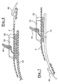
- Les figures 6
et 7 sont des vues en coupe longitudinales de la languette du mécanisme de blocage montrées pour deux variantes de réalisation. - La figure 8 est une vue en perspective sommaire d'une chaussure de ski équipée d'une variante de réalisation du dispositif de serrage.
- Figure 1 is a brief perspective view of a fastener equipped with the locking device.
- Figure 2 is a brief perspective view of the locking area of the clamping device.
- Figure 3 is an exploded view showing the different elements illustrated in Figure 2, separately.
- FIG. 4 is a longitudinal sectional view of the locking mechanism of FIG.
- Figure 5 is a top view showing the guide and the complementary piece.
- Figures 6 and 7 are longitudinal sectional views of the tongue of the locking mechanism shown for two variants.
- Figure 8 is a summary perspective view of a ski boot equipped with an alternative embodiment of the clamping device.
Comme déjà évoqué, l'invention concerne un dispositif de serrage qui peut trouver une application toute particulière dans les sports de glisse, et notamment pour les chaussures de ski et les fixations de surf.As already mentioned, the invention relates to a clamping device which can find a particular application in sliding sports, and in particular for ski boots and surf bindings.
Dans son application aux fixations de surf, tel qu'illustré à la figure 1, l'invention permet d'équiper une fixation (1) du type "coque" qui comprend une embase (2), une coque arrière (3), et deux sangles (4, 5), reliant les deux côtés de l'embase (2), en passant respectivement au dessus du cou de pied et au dessus de l'articulation métatarsophalangienne.In its application to surf bindings, as illustrated in FIG. 1, the invention makes it possible to equip a fastener (1) of the "shell" type which comprises a base (2), a rear shell (3), and two straps (4, 5), connecting the two sides of the base (2), passing respectively above the instep and above the metatarsophalangeal joint.
Chacune de ces sangles (4, 5) comprend une languette crantée rectiligne (6, 7) qui est solidarisée par une extrémité (8, 9) à un côté de l'embase. L'autre partie de la sangle (10, 11) est solidaire de l'autre côté de l'embase. Cette partie (10, 11) qui passe au dessus de la chaussure est généralement élargie et rembourrée pour répartir la pression qu'elle exerce sur la chaussure, et éviter qu'elle ne blesse l'utilisateur. Dans sa portion extrémale, cette partie de la sangle (10, 11) comprend un mécanisme de serrage (12, 13) réalisé conformément à l'invention. Ce dispositif de serrage (12, 13) peut être de différentes conceptions, comme illustré à la figure 1. De façon générale, ces mécanismes de blocage (12, 13) comprennent un guide dans lequel coulisse la languette crantée (6, 7), et un système de cliquet, qui coopère avec la languette (6, 7) pour en empêcher le coulissement à l'intérieur du guide, dans un sens qui desserrerait la sangle.Each of these straps (4, 5) comprises a rectilinear notched tongue (6, 7) which is secured by one end (8, 9) to one side of the base. The other part of the strap (10, 11) is secured to the other side of the base. This portion (10, 11) which passes over the shoe is generally enlarged and padded to distribute the pressure it exerts on the shoe, and prevent it hurts the user. In its extremal portion, this portion of the strap (10, 11) comprises a clamping mechanism (12, 13) made according to the invention. This clamping device (12, 13) can be of different designs, as illustrated in FIG. 1. In general, these locking mechanisms (12, 13) comprise a guide in which the notched tongue (6, 7) slides, and a ratchet system, which cooperates with the tongue (6, 7) to prevent sliding within the guide, in a direction that would loosen the strap.
Dans une forme plus perfectionnée, telle qu'illustrée à la figure 2, le mécanisme de serrage comprend également un levier (50) qui coopère avec la languette (6) pour en provoquer l'avancement à l'intérieur du guide, dans le sens du serrage. Ce levier additionnel (50), qui peut être avantageux, n'est toutefois pas nécessaire pour la mise en oeuvre de l'invention.In a more advanced form, as illustrated in Figure 2, the clamping mechanism also comprises a lever (50) which cooperates with the tongue (6) to cause the advancement inside the guide, in the direction tightening. This additional lever (50), which may be advantageous, is however not necessary for the implementation of the invention.
Les différents éléments formant le mécanisme de serrage sont illustrés de façon séparée à la figure 3. Ainsi, à l'extrémité (17) de la sangle (12) est solidarisé l'ensemble formé par la pièce complémentaire (20), le guide (30), le cliquet (40), et le levier de serrage (50). Cette solidarisation peut par exemple être effectuée par un rivet (18) traversant un perçage (31) réalisé dans le guide (30) et un perçage (21) formé dans la partie centrale (22) de la pièce complémentaire (20), ainsi qu'un perçage (19) réalisé dans la sangle (12).The various elements forming the clamping mechanism are illustrated separately in FIG. 3. Thus, at the end (17) of the strap (12) is secured the assembly formed by the complementary piece (20), the guide ( 30), the pawl (40), and the clamping lever (50). This joining can for example be carried out by a rivet (18) passing through a bore (31) formed in the guide (30) and a bore (21) formed in the central portion (22) of the complementary piece (20), as well as a bore (19) formed in the strap (12).
La pièce complémentaire (20) comprend une partie centrale (22), deux parois latérales (23, 24) situées de part et d'autre de la partie centrale (22). Ces parois latérales (23, 24) se prolongent à l'avant par des parois divergentes (25, 26) qui s'évasent en s'écartant du corps de la pièce (20). Sur chaque face extérieure des parois latérales (23, 24), la pièce complémentaire (20) comporte une zone de préhension (27, 28), légèrement en excroissance. La forme de ces zones de préhension est déterminée par des considérations ergonomiques. Une des deux zones de préhension (27, 28) peut être décalée longitudinalement par rapport à l'autre, pour tenir compte de la différence de positionnement du pouce et de l'index lorsque la pièce (20) est saisie par l'utilisateur.The complementary piece (20) comprises a central portion (22), two side walls (23, 24) located on either side of the central portion (22). These side walls (23, 24) are extended at the front by diverging walls (25, 26) which flare away from the body of the workpiece (20). On each outer face of the side walls (23, 24), the complementary piece (20) comprises a gripping zone (27, 28), slightly outgrowth. The shape of these gripping areas is determined by ergonomic considerations. One of the two gripping areas (27, 28) may be offset longitudinally relative to the other, to account for the difference in positioning of the thumb and index finger when the workpiece (20) is grasped by the user.
Comme illustré à la figure 3, la partie centrale (22) de la pièce complémentaire (20) comprend un léger renfoncement, délimité par la surépaisseur (29), à l'intérieur duquel vient s'encastrer le guide (30). Le guide (30) comprend également une zone centrale (32) venant prendre place dans le renfoncement de la pièce complémentaire (20). De chaque côté, le guide (30) comprend des parois latérales (33), qui sont planes et parallèles. A proximité de l'ouverture (34) du guide, ces parois latérales (33) possèdent un prolongement (35) s'écartant de la paroi latérale (33) vers l'extérieur. Ces portions de prolongement (35) viennent s'encastrer dans une partie des parois divergentes (25, 26) de la pièce complémentaire (20). Les deux parois latérales (33) des guides (30) sont percées chacune d'une paire d'ouvertures (36, 37) recevant les axes (41, 51) respectivement du cliquet (40) et du levier (50).As illustrated in Figure 3, the central portion (22) of the complementary piece (20) comprises a slight recess, delimited by the extra thickness (29), within which is embedded the guide (30). The guide (30) also comprises a central zone (32) to take place in the recess of the complementary piece (20). On each side, the guide (30) comprises side walls (33), which are flat and parallel. Near the opening (34) of the guide, these side walls (33) have an extension (35) away from the side wall (33) to the outside. These extension portions (35) are embedded in a portion of the diverging walls (25, 26) of the complementary piece (20). The two side walls (33) of the guides (30) are each pierced by a pair of openings (36, 37) receiving the axes (41, 51) respectively of the pawl (40) and the lever (50).
Dans sa partie centrale, le guide (30) comporte une découpe permettant de former un ergot (38) déformé vers le bas, pour venir s'encastrer dans une ouverture (39) ménagée à cet effet dans la pièce complémentaire (20). De la sorte, le centrage et le blocage du guide (30) à l'intérieur de la pièce complémentaire (20) sont assurés.In its central part, the guide (30) has a cutout for forming a lug (38) deformed downwards, to fit into an opening (39) provided for this purpose in the complementary piece (20). In this way, the centering and locking of the guide (30) inside the complementary piece (20) are ensured.
Le guide (30) reçoit donc, comme illustré à la figure 3, le cliquet (40) assurant le blocage de la languette (6) à l'intérieur du guide (30). Pour ce faire, le cliquet (40) possède une arête (42) qui vient s'encastrer dans un cran de la languette (6). Une pression sur la zone d'appui (43) du cliquet (40) assure le pivotement de ce dernier et un désenclenchement de l'arête (42) du cran de la languette (6). Cette manoeuvre autorise donc le desserrage de la sangle.The guide (30) therefore receives, as shown in Figure 3, the pawl (40) ensuring the locking of the tongue (6) within the guide (30). To do this, the pawl (40) has an edge (42) which is embedded in a notch of the tongue (6). Pressure on the support zone (43) of the pawl (40) ensures pivoting of the latter and disengagement of the edge (42) of the notch of the tongue (6). This maneuver therefore allows the loosening of the strap.
A l'inverse, le serrage est provoqué par la manoeuvre du levier (50). Lorsque ce levier (50) est soulevé, son arête (52) vient au contact d'un cran de la languette (6), en repoussant ce dernier dans le sens de l'avancée à l'intérieur du guide (30).Conversely, the tightening is caused by the operation of the lever (50). When this lever (50) is raised, its edge (52) comes into contact with a notch of the tongue (6), pushing the latter in the direction of advancing inside the guide (30).
Comme illustré à la figure 5, la largeur λ1 de la languette est sensiblement égale à la distance (λ2) qui sépare les faces internes des parois (33) du guide (30). De la sorte, le guidage de la languette s'effectue quasiment sans aucun jeu transversal, et donc aucune imprécision dans le serrage. En revanche, la largeur L de la pièce complémentaire, mesurée au niveau de son ouverture, entre les parois divergentes (25, 26), est nettement supérieure à la largeur λ1 de la languette (6), de sorte que, même si la languette n'est pas présentée dans l'axe du guide (30), celle-ci est automatiquement rabattue dans la bonne direction par les parois divergentes (25, 26) caractéristiques.As illustrated in FIG. 5, the width λ 1 of the tongue is substantially equal to the distance (λ 2 ) which separates the internal faces of the walls (33) of the guide (30). In this way, the guidance of the tongue is carried out almost without any transverse play, and therefore no inaccuracy in tightening. On the other hand, the width L of the complementary part, measured at its opening, between the diverging walls (25, 26) is clearly greater than the width λ 1 of the tongue (6), so that, even if the tongue is not presented in the axis of the guide (30), it is automatically folded in the right direction by the diverging walls (25, 26) characteristics.
L'invention n'est pas limitée à l'emploi d'un levier provoquant l'avancement de la languette à l'intérieur du mécanisme de blocage, mais couvre également d'autres variantes dans lesquelles le guide (30) et la pièce complémentaire (20) ne comportent qu'un cliquet de blocage.The invention is not limited to the use of a lever causing the advancement of the tongue inside the locking mechanism, but also covers other variants in which the guide (30) and the complementary piece (20) have only one locking pawl.
Dans ce cas, l'avancée de la languette peut être provoquée de différentes manières. Ainsi, comme illustré à la figure 6, la languette (6) peut être associée à une boucle articulée (60), située à son extrémité la raccordant à l'embase de la fixation. La manoeuvre de la boucle (60) provoque l'allongement de la languette (6) et son introduction à l'intérieur du guide (30). La manoeuvre inverse de la boucle (60) provoque une traction sur la languette, et donc sur l'ensemble du guide et de la pièce complémentaire lorsque le cliquet rentre en action.In this case, the advance of the tongue can be caused in different ways. Thus, as illustrated in Figure 6, the tongue (6) can be associated with an articulated loop (60), located at its end connecting to the base of the fastener. The operation of the loop (60) causes the extension of the tongue (6) and its introduction into the guide (30). The reverse operation of the loop (60) causes a pull on the tongue, and therefore on the entire guide and the complementary piece when the pawl comes into action.
Dans une autre forme de réalisation illustrée à la figure 7, c'est la sangle (12) qui supporte le guide (30) et la pièce complémentaire (20) qui est associée à une boucle déformable (62). Dans ce cas, lorsque cette boucle (62) est manoeuvrée, le guide (30) et la pièce complémentaire (20) sont déplacés en direction de la languette (6), provoquant la pénétration de cette dernière dans le guide (30). La manoeuvre inverse de la boucle assure une traction sur la sangle (12), et donc sur le guide (30) et le cliquet (40). Lorsque ce dernier rentre en action, il assure donc une traction sur la languette (6), et donc un serrage de la sangle.In another embodiment illustrated in Figure 7, it is the strap (12) which supports the guide (30) and the complementary piece (20) which is associated with a deformable loop (62). In this case, when this loop (62) is operated, the guide (30) and the complementary piece (20) are moved towards the tongue (6), causing the penetration of the latter in the guide (30). The reverse operation of the loop ensures traction on the strap (12), and therefore on the guide (30) and the pawl (40). When it comes into action, it ensures traction on the tongue (6), and therefore a tightening of the strap.
L'invention peut également être employée sur des chaussures de ski ou analogue, comme illustré à la figure 8. Dans ce cas, le dispositif de serrage relie les rabats avant (66) et arrière (65) d'une chaussure. Dans la forme illustrée, la languette (67) est solidaire du rabat avant (66) et le rabat arrière (65) comporte le mécanisme de blocage. Ce dernier est équipé de la pièce caractéristique (68) facilitant l'introduction de la languette (67) dans le mécanisme de blocage.The invention can also be used on ski boots or the like, as illustrated in FIG. 8. In this case, the clamping device connects the front (66) and rear (65) flaps of a boot. In the illustrated form, the tongue (67) is integral with the front flap (66) and the rear flap (65) has the locking mechanism. The latter is equipped with the characteristic piece (68) facilitating the insertion of the tongue (67) into the locking mechanism.
Il ressort de ce qui précède que l'utilisation des moyens de serrage décrits ci-avant présente de multiples avantages, et notamment :
- ■ l'assurance d'une bonne introduction de la languette dans le guide de blocage, même lorsque la languette n'est pas amenée exactement dans l'axe du guide, par exemple lorsque l'utilisateur n'a pas toute la précision voulue à cause de ses gants ;
- ■ une plus grande facilité et une plus grande rapidité de mise en place ;
- ■ la possibilité d'adapter la pièce complémentaire caractéristique à certaines boucles existantes.
- ■ the guarantee of a good introduction of the tongue in the locking guide, even when the tongue is not brought exactly in the axis of the guide, for example when the user does not have all the precision required to because of his gloves;
- ■ greater ease and speed of implementation;
- ■ the possibility of adapting the characteristic complementary piece to certain existing loops.
Le dispositif de serrage conforme à l'invention peut comme déjà évoqué, être employé pour de multiples applications, et notamment dans les sports de glisse pour des fixations de surf, des chaussures de ski alpin, de fond ou analogue, ainsi que des bottes de surf.The clamping device according to the invention can as already mentioned, be used for multiple applications, and especially in surf sports for surf bindings, alpine ski boots, bottom or the like, and boots of surf.
Il peut également être utilisé en tant que moyen de serrage pour des harnais ou autres, ou bien encore des sacs de sport.It can also be used as a clamping means for harnesses or other, or even sports bags.
Claims (12)
- Device for clamping together two parts of a sports article, including:• a rectilinear notched tongue (6), integral with a first part of the sports article;• a guide (30) integral with the second part of the sports article, said guide having two walls (33) between which said tongue (6) is able to slide;• a pawl (40) articulated on the guide (30), capable of interacting with the notched tongue (6) in order to immobilize it in position relative to the guide (30);characterized in that it also includes a complementary piece (20) in which the guide (30) is nested, the portion of the complementary piece (20) located on the side with the opening of the guide (30) via which the tongue (6), including two divergent walls (25, 26) which flare out and extend beyond the opening of the guide (30).
- Device according to Claim 1, characterized in that the divergent walls (25, 26) of the complementary piece (20) extend via lateral walls (23, 24) opposite the walls (33) of the guide (30).
- Device according to Claim 2, characterized in that it includes means for centring the guide (30) relative to the complementary piece (20).
- Device according to Claim 3, characterized in that the centring means are formed by a stud (38) and a corresponding aperture (39) which are located on the guide (30) and on the complementary piece (20)
- Device according to Claim 2, characterized in that the walls (33) of the guide extend via divergent walls (35) in contact with a part of the inner faces of the divergent walls (25, 26) of the complementary piece (20).
- Device according to Claim 2, characterized in that the lateral walls (23, 24) of the complementary piece form zones (27, 28) for gripping the guide (30).
- Device according to Claim 6, characterized in that the two lateral walls (27, 28) of the complementary piece are asymmetrical.
- Device according to Claim 1, characterized in that the guide (30) includes a lever (50) interacting with the tongue (6) in order to cause the latter to advance in the guide (30).
- Device according to Claim 1, characterized in that it includes an articulated buckle (60) integral with the tongue (6) and ensuring the displacement of the tongue (6) inside the guide (30).
- Device according to Claim 1, characterized in that it includes an articulated buckle (62) integral with the guide (30) and with the complementary piece (20) and ensuring the displacement of the guide (30) relative to the tongue (6).
- Snowboard binding equipped with at least one clamping device according to one Claims 1 to 10, in which the two parts to be clamped together are the parts of a clamping strap (4, 5).
- Gliding-sport boot equipped with at least one device according to one of Claims 1 to 10, in which the two parts to be clamped together are two flaps (66, 65) of the boot, one (66) of which carries the tongue (67) and the other the guide and the complementary piece (68).
Applications Claiming Priority (2)
| Application Number | Priority Date | Filing Date | Title |
|---|---|---|---|
| FR0109473A FR2827185B1 (en) | 2001-07-16 | 2001-07-16 | DEVICE INTENDED TO ENSURE THE TIGHTENING OF TWO PARTS OF A SPORTS ARTICLE |
| FR0109473 | 2001-07-16 |
Publications (2)
| Publication Number | Publication Date |
|---|---|
| EP1277414A1 EP1277414A1 (en) | 2003-01-22 |
| EP1277414B1 true EP1277414B1 (en) | 2006-04-12 |
Family
ID=8865562
Family Applications (1)
| Application Number | Title | Priority Date | Filing Date |
|---|---|---|---|
| EP02356123A Expired - Lifetime EP1277414B1 (en) | 2001-07-16 | 2002-07-02 | Apparatus for tightening two parts of an sport article |
Country Status (5)
| Country | Link |
|---|---|
| US (1) | US6694644B2 (en) |
| EP (1) | EP1277414B1 (en) |
| AT (1) | ATE322844T1 (en) |
| DE (1) | DE60210542T2 (en) |
| FR (1) | FR2827185B1 (en) |
Families Citing this family (18)
| Publication number | Priority date | Publication date | Assignee | Title |
|---|---|---|---|---|
| TW588589U (en) * | 2003-01-30 | 2004-05-21 | Taiwan Ind Fastener Corp | Minutely-adjustable slidable buckle |
| US7614638B2 (en) * | 2004-08-02 | 2009-11-10 | The Burton Corporation | Convertible toe strap |
| US7950072B1 (en) | 2005-06-03 | 2011-05-31 | Violet Hanson | Reversible belt with slide buckle |
| ITTV20050053U1 (en) * | 2005-10-25 | 2007-04-26 | Emmepi Srl | CLOSING DEVICE, PARTICULARLY FOR A SPORTS FOOTWEAR |
| FR2896700A1 (en) * | 2006-01-27 | 2007-08-03 | Skis Rossignol Sas Soc Par Act | FASTENING LOOP WITH SECURED ACCOMMODATION ELEMENT |
| US8236080B2 (en) * | 2008-12-15 | 2012-08-07 | Mann & Hummel Gmbh | Ratchet clip |
| FR2940133B1 (en) * | 2008-12-23 | 2011-01-07 | Salomon Sas | ASSEMBLY COMPRISING A RATCHET DEVICE AND A BAND |
| USD611237S1 (en) | 2009-06-05 | 2010-03-09 | Dashamerica, Inc. | Cycling shoe insole |
| USD636983S1 (en) | 2009-06-05 | 2011-05-03 | Dashamerica, Inc. | Cycling shoe |
| USD630419S1 (en) | 2009-06-05 | 2011-01-11 | Dashamerica, Inc. | Base plate for adjustable strap |
| US10271610B2 (en) * | 2010-10-21 | 2019-04-30 | Heidi Henkel | Flexible and precisely fitting ski boot for maximum efficiency and foot and leg health during Nordic skiing |
| US20120297591A1 (en) * | 2011-05-27 | 2012-11-29 | Pearl Izumi | Selectively Releasable Buckle |
| US8763209B2 (en) | 2011-08-23 | 2014-07-01 | The Burton Corporation | Ratchet buckle and strap assembly |
| US9351539B2 (en) | 2012-12-11 | 2016-05-31 | Bell Sports, Inc. | Controlled release buckle |
| US9566499B2 (en) * | 2015-02-07 | 2017-02-14 | Daniel C. Sullivan | Binding strap assist mechanism with a torsion spring |
| US9737787B2 (en) | 2015-02-07 | 2017-08-22 | Daniel C. Sullivan | Binding strap assist mechanism |
| US10618730B2 (en) * | 2015-03-02 | 2020-04-14 | Grigooris MANSSOURIAN | Retainer mechanism |
| US11299101B2 (en) * | 2019-08-21 | 2022-04-12 | Ford Global Technologies, Llc | Attachment assembly |
Citations (1)
| Publication number | Priority date | Publication date | Assignee | Title |
|---|---|---|---|---|
| EP1203540A1 (en) * | 2000-11-01 | 2002-05-08 | The Burton Corporation | Fastening assembly and method for securing footwear to a binding |
Family Cites Families (11)
| Publication number | Priority date | Publication date | Assignee | Title |
|---|---|---|---|---|
| US3662435A (en) * | 1970-08-06 | 1972-05-16 | Allsop I J | Ratcheting buckle for ski boots and the like |
| US4193171A (en) * | 1978-09-18 | 1980-03-18 | Abraham Lichowsky | Ski boot tightening buckle |
| IT223068Z2 (en) * | 1990-11-19 | 1995-06-09 | Everest Off | STRUCTURE OF CLAMPING DEVICE, PARTICULARLY FOR FOOTWEAR |
| WO1997028859A1 (en) | 1996-02-06 | 1997-08-14 | Preston Binding Company | Snowboard binding assembly |
| US5606779A (en) * | 1996-05-28 | 1997-03-04 | Monotype Supply Co., Ltd. | Microscopically adjustable buckle for shoes |
| EP0809950B1 (en) * | 1996-05-30 | 2002-04-17 | Bauer Italia S.p.A. | A device for adjusting and clamping the toothed strap of a fastening for sports footwear |
| FR2749738B1 (en) * | 1996-06-13 | 1998-09-11 | Salomon Sa | DEVICE FOR CLAMPING WITH A TOOTHED STRAP AND RATCHET LOCKING MEMBER |
| US5745959A (en) | 1997-01-07 | 1998-05-05 | The Burton Corporation | Ratchet-type buckle |
| IT236439Y1 (en) * | 1997-02-04 | 2000-08-17 | Giuseppe Cavasin | CLAMPING DEVICE, ESPECIALLY FOR SPORTS SHOES |
| IT251508Y1 (en) * | 2000-02-10 | 2003-11-19 | Everest Spa | CLOSING DEVICE FOR FOOTWEAR AND LOCKING OF FOOTWEAR WITH SPORTS EQUIPMENT |
| US6499197B1 (en) * | 2001-09-05 | 2002-12-31 | Han-Ching Huang | Buckle device with improved safety |
-
2001
- 2001-07-16 FR FR0109473A patent/FR2827185B1/en not_active Expired - Fee Related
-
2002
- 2002-07-02 AT AT02356123T patent/ATE322844T1/en not_active IP Right Cessation
- 2002-07-02 DE DE60210542T patent/DE60210542T2/en not_active Expired - Lifetime
- 2002-07-02 EP EP02356123A patent/EP1277414B1/en not_active Expired - Lifetime
- 2002-07-15 US US10/195,277 patent/US6694644B2/en not_active Expired - Fee Related
Patent Citations (1)
| Publication number | Priority date | Publication date | Assignee | Title |
|---|---|---|---|---|
| EP1203540A1 (en) * | 2000-11-01 | 2002-05-08 | The Burton Corporation | Fastening assembly and method for securing footwear to a binding |
Also Published As
| Publication number | Publication date |
|---|---|
| US6694644B2 (en) | 2004-02-24 |
| FR2827185A1 (en) | 2003-01-17 |
| DE60210542T2 (en) | 2006-11-09 |
| EP1277414A1 (en) | 2003-01-22 |
| DE60210542D1 (en) | 2006-05-24 |
| FR2827185B1 (en) | 2003-09-05 |
| US20030009918A1 (en) | 2003-01-16 |
| ATE322844T1 (en) | 2006-04-15 |
Similar Documents
| Publication | Publication Date | Title |
|---|---|---|
| EP1277414B1 (en) | Apparatus for tightening two parts of an sport article | |
| EP0169080B1 (en) | Fastening device for a shoe to a pedal, shoe and pedal provided with this device | |
| EP0812552B1 (en) | Tightening device with serrated strap and ratchet lock | |
| EP0650385B1 (en) | Device for holding a boot on a snowboard | |
| EP1512440B1 (en) | Fastening device for a boot or a shoe on a sporting good | |
| EP1147791B1 (en) | Snowboard or skateboard boot binding | |
| EP1690462A1 (en) | Lacing device for a sports shoe | |
| FR2758057A1 (en) | CLAMP LOOP FOR ADJUSTING A STRAP | |
| CH673754A5 (en) | ||
| FR2767486A1 (en) | DEVICE FOR RETAINING A SHOE ON A SNOWBOARD INTENDED FOR SNOW SURFING | |
| EP1935461B1 (en) | Article comprising a button mobile between at least two positions | |
| EP1358916B1 (en) | A sport shoe for practising a gliding sport or snowboard binding with snap fastener flaps | |
| EP0956886B1 (en) | Interface between a boot and a snowboard | |
| EP1325768B1 (en) | Cross-country ski binding | |
| EP0548468B1 (en) | Intermediate piece for the sliding rail of a binding element, particularly for ski bindings | |
| EP1327467A1 (en) | Device for retaining a shoe to a sporting article | |
| EP3741436A1 (en) | Binding device for fixing a boot onto a snowboard | |
| FR3096273A1 (en) | Binding device for attaching a shoe to a sliding board | |
| WO1996022034A1 (en) | Locking and tightening device | |
| EP0983778A1 (en) | Dismountable stop device for a slidable body of a ski binding | |
| FR2848869A1 (en) | Snowboard boot retaining device comprises lateral and medial parts delimiting boot reception zone with link connected to each part, portion of link lateral and medial portions able to be separated from reception zone | |
| FR2749520A1 (en) | Strap in two parts holding boot on snow-board | |
| FR2925345A1 (en) | Sports article i.e. foot/inline skate shoe retaining device, for use on snowboard for practicing e.g. snowsurfing, has stop limiting connection extension and unit controlling attachment to release ends when connection attains maximum length | |
| CH656542A5 (en) | SECURITY FIXING FOR SKIING. | |
| FR3107193A1 (en) | Braking device for ski touring |
Legal Events
| Date | Code | Title | Description |
|---|---|---|---|
| PUAI | Public reference made under article 153(3) epc to a published international application that has entered the european phase |
Free format text: ORIGINAL CODE: 0009012 |
|
| AK | Designated contracting states |
Kind code of ref document: A1 Designated state(s): AT BE BG CH CY CZ DE DK EE ES FI FR GB GR IE IT LI LU MC NL PT SE SK TR |
|
| AX | Request for extension of the european patent |
Free format text: AL;LT;LV;MK;RO;SI |
|
| 17P | Request for examination filed |
Effective date: 20030401 |
|
| AKX | Designation fees paid |
Designated state(s): AT DE FR IT |
|
| 17Q | First examination report despatched |
Effective date: 20050223 |
|
| GRAP | Despatch of communication of intention to grant a patent |
Free format text: ORIGINAL CODE: EPIDOSNIGR1 |
|
| GRAS | Grant fee paid |
Free format text: ORIGINAL CODE: EPIDOSNIGR3 |
|
| GRAA | (expected) grant |
Free format text: ORIGINAL CODE: 0009210 |
|
| RAP1 | Party data changed (applicant data changed or rights of an application transferred) |
Owner name: SKIS ROSSIGNOL |
|
| AK | Designated contracting states |
Kind code of ref document: B1 Designated state(s): AT DE FR IT |
|
| PG25 | Lapsed in a contracting state [announced via postgrant information from national office to epo] |
Ref country code: IT Free format text: LAPSE BECAUSE OF FAILURE TO SUBMIT A TRANSLATION OF THE DESCRIPTION OR TO PAY THE FEE WITHIN THE PRESCRIBED TIME-LIMIT;WARNING: LAPSES OF ITALIAN PATENTS WITH EFFECTIVE DATE BEFORE 2007 MAY HAVE OCCURRED AT ANY TIME BEFORE 2007. THE CORRECT EFFECTIVE DATE MAY BE DIFFERENT FROM THE ONE RECORDED. Effective date: 20060412 |
|
| REF | Corresponds to: |
Ref document number: 60210542 Country of ref document: DE Date of ref document: 20060524 Kind code of ref document: P |
|
| PLBE | No opposition filed within time limit |
Free format text: ORIGINAL CODE: 0009261 |
|
| STAA | Information on the status of an ep patent application or granted ep patent |
Free format text: STATUS: NO OPPOSITION FILED WITHIN TIME LIMIT |
|
| 26N | No opposition filed |
Effective date: 20070115 |
|
| PG25 | Lapsed in a contracting state [announced via postgrant information from national office to epo] |
Ref country code: AT Free format text: LAPSE BECAUSE OF NON-PAYMENT OF DUE FEES Effective date: 20060702 |
|
| PGFP | Annual fee paid to national office [announced via postgrant information from national office to epo] |
Ref country code: DE Payment date: 20130812 Year of fee payment: 12 |
|
| REG | Reference to a national code |
Ref country code: DE Ref legal event code: R119 Ref document number: 60210542 Country of ref document: DE |
|
| PG25 | Lapsed in a contracting state [announced via postgrant information from national office to epo] |
Ref country code: DE Free format text: LAPSE BECAUSE OF NON-PAYMENT OF DUE FEES Effective date: 20150203 |
|
| REG | Reference to a national code |
Ref country code: DE Ref legal event code: R119 Ref document number: 60210542 Country of ref document: DE Effective date: 20150203 |
|
| REG | Reference to a national code |
Ref country code: FR Ref legal event code: PLFP Year of fee payment: 15 |
|
| REG | Reference to a national code |
Ref country code: FR Ref legal event code: PLFP Year of fee payment: 16 |
|
| REG | Reference to a national code |
Ref country code: FR Ref legal event code: PLFP Year of fee payment: 17 |
|
| PGFP | Annual fee paid to national office [announced via postgrant information from national office to epo] |
Ref country code: FR Payment date: 20180728 Year of fee payment: 17 |
|
| PG25 | Lapsed in a contracting state [announced via postgrant information from national office to epo] |
Ref country code: FR Free format text: LAPSE BECAUSE OF NON-PAYMENT OF DUE FEES Effective date: 20190731 |