EP1512440B1 - Fastening device for a boot or a shoe on a sporting good - Google Patents
Fastening device for a boot or a shoe on a sporting good Download PDFInfo
- Publication number
- EP1512440B1 EP1512440B1 EP04017910A EP04017910A EP1512440B1 EP 1512440 B1 EP1512440 B1 EP 1512440B1 EP 04017910 A EP04017910 A EP 04017910A EP 04017910 A EP04017910 A EP 04017910A EP 1512440 B1 EP1512440 B1 EP 1512440B1
- Authority
- EP
- European Patent Office
- Prior art keywords
- medial
- lateral
- support element
- rear support
- foot
- Prior art date
- Legal status (The legal status is an assumption and is not a legal conclusion. Google has not performed a legal analysis and makes no representation as to the accuracy of the status listed.)
- Not-in-force
Links
Images


Classifications
-
- A—HUMAN NECESSITIES
- A63—SPORTS; GAMES; AMUSEMENTS
- A63C—SKATES; SKIS; ROLLER SKATES; DESIGN OR LAYOUT OF COURTS, RINKS OR THE LIKE
- A63C10/00—Snowboard bindings
- A63C10/28—Snowboard bindings characterised by auxiliary devices or arrangements on the bindings
- A63C10/285—Pads as foot or binding supports, e.g. pads made of foam
-
- A—HUMAN NECESSITIES
- A63—SPORTS; GAMES; AMUSEMENTS
- A63C—SKATES; SKIS; ROLLER SKATES; DESIGN OR LAYOUT OF COURTS, RINKS OR THE LIKE
- A63C10/00—Snowboard bindings
- A63C10/02—Snowboard bindings characterised by details of the shoe holders
- A63C10/04—Shoe holders for passing over the shoe
-
- A—HUMAN NECESSITIES
- A63—SPORTS; GAMES; AMUSEMENTS
- A63C—SKATES; SKIS; ROLLER SKATES; DESIGN OR LAYOUT OF COURTS, RINKS OR THE LIKE
- A63C10/00—Snowboard bindings
- A63C10/02—Snowboard bindings characterised by details of the shoe holders
- A63C10/04—Shoe holders for passing over the shoe
- A63C10/06—Straps therefor, e.g. adjustable straps
-
- A—HUMAN NECESSITIES
- A63—SPORTS; GAMES; AMUSEMENTS
- A63C—SKATES; SKIS; ROLLER SKATES; DESIGN OR LAYOUT OF COURTS, RINKS OR THE LIKE
- A63C10/00—Snowboard bindings
- A63C10/24—Calf or heel supports, e.g. adjustable high back or heel loops
Definitions
- the invention relates to a device for holding a foot or a shoe on a sports machine, for which the maintenance of the foot or the shoe is done using at least one link.
- the invention also relates to a link intended to be part of the device.
- Such devices are used for snowboarding or snowboarding, skiing on snow or water, snowshoeing, rollerblading, or other.
- a link device generally comprises a lateral part and a medial part which delimit between them a reception area of the foot or boot, as well as a rear support element associated with at least one of lateral and medial parts.
- the rear support element comprises a bearing face, turned towards the reception area and intended to receive the rear of a lower leg.
- the rear support element also comprises a free face opposite to the bearing face.
- the device further comprises at least one link that extends between the lateral and medial parts, each link serving to maintain the foot or the shoe in the reception area.
- the link is generally an elongated piece relatively flexible and substantially inextensible. Its flexibility allows it to adapt to the foot or the shoe. Its relative inextensibility favors the maintenance of the foot or the shoe in the zone of reception.
- a front edge grip can cause a heel lift, which is detrimental to driving precision.
- a link that includes a front division and a rear division.
- the front division is in front of the lower leg and substantially above the instep, while the rear division is behind the lower leg and above the heel.
- the divisions unite to gird the lower leg just above the heel.
- the invention aims to remedy these drawbacks and in particular to improve the holding of the foot or the shoe at the heel, and simultaneously improve the holding of the back of the lower leg on the rear support element.
- the invention proposes a device for maintaining a foot or a shoe, the device comprising a lateral part and a medial part delimiting an area for receiving the foot or footwear, as well as an element rear support member associated with at least one of the lateral and medial parts, the rear support element comprising a bearing face facing towards the receiving zone and a free face opposite the bearing face.
- the device further comprising a link extending between the lateral and medial portions, the link comprising a front division as well as a rear division.
- the holding device according to the invention is characterized in that the front division of the link is located on the side of the bearing surface of the rear support element, and the rear division is located on the side of the face. free of the back support element.
- the link plate the back of the lower leg against the back support element. Therefore it allows the maintenance with a low game, or zero, both the heel in the reception area and the back of the lower leg against the rear support element. It follows that for the back of the foot or the shoe, the holding accuracy is distributed homogeneously. An advantage that results is a high precision of conduct in all cases.
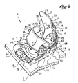
- the first example is presented using the Figures 1 to 5 .
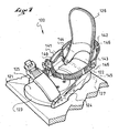
- a holding device 1 allows the temporary retention on a board 2 of a shoe 3.
- the holding device 1 comprises a base 4 which extends longitudinally between a rear end 5 and a front end 6.
- the base 4 has an upper face 7 designed to be facing the sole 8 of the shoe 3, and a lower face 9 provided to be above the board 2.
- the base 4 is retained in the board 2 by means represented in the form of a disc 10, itself retained in the board 2 by screws 11.
- the base 4 is bordered laterally by a lateral flange 12 and by a medial flange 13.
- Each of the flanges 12, 13 form respectively a lateral or medial part of the device 1 to define a reception zone 14 of the shoe.
- the flanges 12, 13 along the sole 8 laterally.
- it could be provided other than the flanges 12, 13 to form the lateral and medial parts.
- simple lateral and medial abutments may be suitable.
- the base 4 and the flanges 12, 13 form a one-piece piece made for example of synthetic material.
- the flanges are parts secured to the base by any means such as gluing, welding, screwing, interlocking, or other.
- the device 1 also comprises a rear support element 20, so that the user can take back supports with the lower leg.
- the rear support element 20 comprises a curved plate 21 which extends longitudinally between an attachment end 22 and a free end 23, transversely between a lateral edge 24 and a medial edge 25, and in thickness between a face support 26 and a free face 27.
- the support face 26 is provided to receive the rear of the lower leg of the user, the rear support member 20 and the base 4 being associated accordingly.
- the rear support element 20 is associated with the flanges 12, 13, for example by means of a hinge 28.
- the latter is oriented substantially along a transverse axis 29 of the device 1
- the hinge 28 may comprise any component such as a screw, a rivet, a washer, a nut, a trunnion, or the like.
- the joint 28 allows a movement of bringing the rear support member 20 towards the base 4. A benefit that arises is to facilitate storage.
- rear support element 20 could also be associated directly with the base 4. Or it could be provided that the rear support element 20 is secured directly to the machine, in this case the board 2. It is enough to position it on the machine so that it allows the back supports with the bottom of leg.
- This means is shown in the form of holes 30 formed in the lateral flanges 12 and medial 13. It is for example possible to advance or retreat the rear support element 20 in the direction of the length of the base 4, by disassembly and reassembly of the joint 28. This allows to adjust the device 1 to the length of a shoe.
- the holes 30 could be arranged to allow a height adjustment, in a direction of approximation or removal of the base 4.
- a stop 35 limits the rearward rotation of the eponymous support element 20.
- the stop 35 comprises a cable 36 which bypasses the rear support element 20.
- the path of the cable 36 can be observed on the figures 1 , 2 and 3 .
- the cable may comprise a lateral end 37 and a medial end 38.
- Each of the ends 37, 38 is secured to the lateral flange 12 or medial 13 by any means known to those skilled in the art. The use of a crimped tip may be suitable.
- Each end 37, 38 is secured to the flange 12, 13 substantially close to the front end 6 of the base 4.
- An adjustable shim 39 secured to the rear support element 20 on the side of the free face 27, makes it possible to adjust the angular position of the rear support element relative to the base 4.
- the cable 36 passes through two guides 40, 41 of the rear support element 20 on either side of the wedge 39. Between the guides 40, 41, the cable 36 is held by the wedge 39. It is sufficient to move the wedge 39 closer to or away from the free end 23.
- This means may comprise a screw 42 for tightening or loosening the wedge 39 relative to the rear support element 20. Additional teeth of the wedge 39 and the rear support element 20 allow positioning of the one on the other. These teeth, not shown, are well known to those skilled in the art.
- any other structure to make the stop could be suitable.
- a first link 50 is located forward, at the metatarsophalangeal joint when the foot is maintained.
- a second link 51 is located aft, at the instep when the foot is held.
- Each of the links 50, 51 extends transversely between the flanges 12, 13.
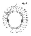
- the second link 51 comprises a front division 52 and a rear division 53.
- the front division 52 of the link 51 is located on the side of the bearing face 26 of the rear support member 20, and the rear division 53 is located on the side of the free face 27 of the rear support element. This allows the second link to grip the rear support member 20 at the same time it holds the foot or the shoe. It follows that the rear of the lower leg is still pressed against the bearing surface 26 of the rear support member 20. A benefit that arises is a direct transmission of driving pulses during rear support. .
- the rear division 53 of the link 51 comprises a lateral foot 60 and a medial foot 61 connected to each other by an arch 62.
- Each of the lateral 60 and medial feet 61 is respectively associated with the lateral and medial flange 12, for example by means of the articulation 28 of axis 29.
- the same joint 28 serves to maintain both the rear support member 20 and the rear division 53 of the link 51.
- a benefit that arises is a simplification of construction.
- Another advantage is to give the rear division 53 a degree of freedom in rotation along the transverse axis 29. This facilitates the establishment of the rear division 53.
- the arch 62 is more easily plate on the free face 27 of the rear support element 20.
- the feet 60, 61 and the arch 62 form a single piece, made for example from a synthetic material.
- Rear division 53 may comprise polyurethane, polyester, polyamide, or the like.
- rear division 53 It can be expected to give rear division 53 a relatively small thickness, for example between 1 and 3 millimeters. This makes it relatively flexible while leaving it substantially inextensible. An advantage that results is a better adaptability to the shapes of a shoe or the rear support element.
- rear division can also be constructed from several parts, assembled by any means known to those skilled in the art.
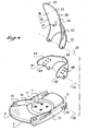
- the front division 52 is associated with the rear division 53. It is represented as a combination of three portions, which are a first attachment portion 63, a cover portion 64 of the shoe, and a second portion of the 65 attachment.
- the first portion 63 has a fastener end 66 and a free end 67.
- the fastener end 66 is connected to the lateral leg 60 by a side fastener.
- the latter is represented in the form of a hinge, made for example by means of a rivet 68.
- a first connecting means is provided for releasably connecting the cover portion 64 to the first portion 63, the free end 67 of the first attachment portion 63 being above the cover portion 64.
- This means includes for example a ratchet clamp mechanism 69 attached to the cover portion 64, at a first end 70 thereof.
- the means for connecting the cover portion 64 to the first portion 63 also comprises a series of teeth 71 shaped on the first portion 63. The teeth 71 are distributed from the free end 67 to the vicinity of the hinge 68.
- the second attachment portion 65 has an attachment end 80 and a free end 81.
- the attachment end 80 is connected to the medial foot 61 by a medial clip.
- the latter is represented in the form of a hinge, made for example by means of a rivet 82.
- a second connecting means is provided for adjustably connecting the cover portion 64 to the second portion 65, the free end 81 of the second attachment portion 65 being above the cover portion 64.
- This means comprises for example a screw 83 which is screwed into the cover portion 64, at a second end 84 thereof. The screw 83 passes through one of the holes 85 drilled in the second portion 65.
- the user can cause the second end 84 of the cover portion 64 to be near the medial foot 61.
- the position adjustment of the cover portion 64 with respect to the second portion 65 is rarely modified. . It is intended to take account of the footprint of the shoe.
- the two joints are substantially along a transverse axis of the device, which allows the front division 52 to cover the shoe uniformly.
- joints could be made by other means such as screws, pins, or other.
- the fasteners of the front division 52 to the rear division 53 could be made by other means, such as a winding around a passer, or the like.
- the front division 52 is substantially inextensible in the direction of its length, that is to say from one foot to the other.
- the materials that constitute it are chosen for this purpose.
- the first and second portions 63, 65 preferably comprise respectively a band 86, 87 lengthened made from a synthetic material, such as a polyamide or polyurethane armed or not.
- Each strip 86, 87 extends in length respectively from the attachment end 66, 80 to the free end 67, 81 of the attachment portion 63, 65.
- the cover portion 64 in turn has an elongated shape. It extends in length between the first 70 and second 84 ends.
- Each portion 63, 64, 65 is more or less flexible. Its curvature is variable, and it can bend to fit the foot or the shoe.
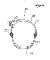
- a rear link 100 is shown in section in a manner similar to the figure 5 .
- the rear link 100 comprises a front division 101 and a rear division 102, the latter passing behind a rear support element 103.
- the second example uses a reduced forward division 101. This one has fewer pieces to cover the shoe. Indeed, it has only a first attachment portion 104 and a cover portion 105, to the exclusion of any other portion. This construction is simpler and more economical.
- a holding device 120 comprises a base 121 which extends longitudinally between a rear end 122 and a front end 123.
- the base 121 is bordered laterally by a lateral flange 124 and by a medial flange 125.
- a rear support element 126 of the device 120 is associated with the base 121, by a means represented in the form of a hinge axis 127. This articulation is between a fastening end 128 of the rear support element 126 and the flanges 124, 125.
- the device 120 comprises a rear link 140, with a front division 141 and a rear division 142.
- the latter 142 comprises a lateral foot 143 and a medial foot 144 both associated with the base 121.
- the association is made under the shape of a joint, along an axis 145, the lateral feet 143 and medial 144 on the lateral flanges 124 and medial 125.
- the hinge pins 127, 145 of the rear support member 126 and the rear link 140 are here different. This makes it possible to adjust the angular position of the rear support element 126 independently of the position of the rear link 140.
- the hinge axis 127 of the rear support element 126 is closer to the base 121 than the hinge axis 145 of the rear link 140. It follows that for the same tightening force of the link 140, the rear division 142 rotates at an angle greater than the rear support element 126. A benefit that results is a greater stability of the angular position of the rear support element 126.
- the link 140 has at least one perforated portion.
- the latter thus has openings 146 which make it lighter and give it a certain ability to deform in torsion.
- An advantage induced by this characteristic is a better adaptation to the shape of the shoe.
- the openwork portion may be furnished with one or more damping cushions.
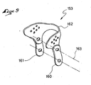
- a rear division 153 of a link comprises a lateral foot 160 and a medial foot 161 connected by an arch 162.
- the lateral 160 and medial 161 feet are hinged relative to the arch 162 along a transverse axis 163.
- the relative articulation of feet 160, 161 and the arch 162 moves the degree of freedom in rotation of the arch upwards, in a direction away from the base.
- the invention is made from materials and according to implementation techniques known to those skilled in the art.
- each of the front and rear divisions is associated with the base.
- association can be direct or indirect.
- each division may have flexible or rigid portions.
- the portions may be hinged together in the manner of the links of a chain.
Abstract
Description
L'invention se rapporte à un dispositif de maintien d'un pied ou d'une chaussure sur un engin de sport, pour lequel le maintien du pied ou de la chaussure se fait à l'aide d'au moins un lien. L'invention se rapporte aussi à un lien destiné à faire partie du dispositif.The invention relates to a device for holding a foot or a shoe on a sports machine, for which the maintenance of the foot or the shoe is done using at least one link. The invention also relates to a link intended to be part of the device.
De tels dispositifs sont utilisés pour la pratique du surf sur neige ou snowboard, du ski sur neige ou sur eau, de la raquette à neige, du patin à roues, ou autre.Such devices are used for snowboarding or snowboarding, skiing on snow or water, snowshoeing, rollerblading, or other.
Un dispositif à liens selon l'art antérieur comprend généralement une partie latérale et une partie médiale qui délimitent entre eux une zone d'accueil du pied ou de la chaussure, ainsi qu'un élément d'appui arrière associé au moins à l'une des parties latérale et médiale. L'élément d'appui arrière comprend une face d'appui, tournée vers la zone d'accueil et destinée à recevoir l'arrière d'un bas de jambe. L'élément d'appui arrière comprend aussi une face libre opposée à la face d'appui. Le dispositif comprend encore au moins un lien qui s'étend entre les parties latérale et médiale, chaque lien servant à maintenir le pied ou la chaussure dans la zone d'accueil.A link device according to the prior art generally comprises a lateral part and a medial part which delimit between them a reception area of the foot or boot, as well as a rear support element associated with at least one of lateral and medial parts. The rear support element comprises a bearing face, turned towards the reception area and intended to receive the rear of a lower leg. The rear support element also comprises a free face opposite to the bearing face. The device further comprises at least one link that extends between the lateral and medial parts, each link serving to maintain the foot or the shoe in the reception area.
Le lien est généralement une pièce allongée relativement souple et sensiblement inextensible. Sa souplesse lui permet de s'adapter au pied ou à la chaussure. Sa relative inextensibilité favorise le maintien du pied ou de la chaussure dans la zone d'accueil.The link is generally an elongated piece relatively flexible and substantially inextensible. Its flexibility allows it to adapt to the foot or the shoe. Its relative inextensibility favors the maintenance of the foot or the shoe in the zone of reception.
Il est fréquent d'utiliser deux liens sur un dispositif, un au niveau de l'articulation métatarsophalangienne, l'autre au niveau du cou-de-pied. Celui qui agit vers le cou-de-pied est généralement orienté pour solliciter le pied ou la chaussure à la fois vers la zone d'accueil et vers l'élément d'appui arrière.It is common to use two links on one device, one at the level of the metatarsophalangeal joint, the other at the level of the instep. The one who acts towards the instep is generally oriented to solicit the foot or the shoe both towards the reception area and towards the rear support element.
C'est par exemple le cas en snowboard où un utilisateur doit prendre des appuis arrière. Le fait que le bas de jambe reste en contact avec l'élément d'appui arrière est gage de précision de conduite.This is for example the case in snowboarding where a user must take backs. The fact that the lower leg remains in contact with the rear support element is a guarantee of driving precision.
Il est cependant apparu que le maintien du talon n'est pas toujours suffisant, et qu'un jeu se crée sous le talon du pied ou de la chaussure. Les impulsions de conduite de l'engin induisent des déplacements du talon.It has appeared, however, that maintaining the heel is not always sufficient, and that a game is created under the heel of the foot or the shoe. The driving impulses of the machine induce movements of the heel.
Par exemple en snowboard une prise de carre avant peut entraîner un soulèvement du talon, ce qui nuit à la précision de conduite.For example in snowboarding a front edge grip can cause a heel lift, which is detrimental to driving precision.
Afin d'améliorer le maintien du talon, l'art antérieur a proposé des solutions.In order to improve the maintenance of the heel, the prior art has proposed solutions.
L'une d'elles, selon le document
C'est notamment le cas en snowboard quand l'utilisateur prend appui sur la carre arrière. Le mouvement d'extension de la jambe est perturbé par le rattrapage du jeu. Cela nuit à la précision de conduite.This is particularly the case in snowboarding when the user is leaning on the rear edge. The leg extension movement is disrupted by catching the game. This affects driving precision.
Ainsi le dispositif selon le document
Par rapport à cela, l'invention a pour but de remédier à ces inconvénients et notamment d'améliorer la tenue du pied ou de la chaussure au niveau du talon, et d'améliorer simultanément la tenue de l'arrière du bas de jambe sur l'élément d'appui arrière.In relation to this, the invention aims to remedy these drawbacks and in particular to improve the holding of the foot or the shoe at the heel, and simultaneously improve the holding of the back of the lower leg on the rear support element.
C'est pourquoi l'invention propose un dispositif de maintien d'un pied ou d'une chaussure, le dispositif comprenant une partie latérale et une partie médiale délimitant une zone d'accueil du pied ou de la chaussure, ainsi qu'un élément d'appui arrière associé au moins à l'une des parties latérale et médiale, l'élément d'appui arrière comprenant une face d'appui tournée vers la zone d'accueil ainsi qu'une face libre opposée à la face d'appui, le dispositif comprenant encore un lien qui s'étend entre les parties latérale et médiale, le lien comprenant une division avant ainsi qu'une division arrière.This is why the invention proposes a device for maintaining a foot or a shoe, the device comprising a lateral part and a medial part delimiting an area for receiving the foot or footwear, as well as an element rear support member associated with at least one of the lateral and medial parts, the rear support element comprising a bearing face facing towards the receiving zone and a free face opposite the bearing face. the device further comprising a link extending between the lateral and medial portions, the link comprising a front division as well as a rear division.
Le dispositif de maintien selon l'invention est caractérisé par le fait que la division avant du lien est située du côté de la face d'appui de l'élément d'appui arrière, et que la division arrière est située du côté de la face libre de l'élément d'appui arrière.The holding device according to the invention is characterized in that the front division of the link is located on the side of the bearing surface of the rear support element, and the rear division is located on the side of the face. free of the back support element.
Ainsi en même temps qu'il ceint le bas de jambe juste au-dessus du talon, le lien plaque l'arrière du bas de jambe contre l'élément d'appui arrière. De ce fait il permet le maintien avec un jeu faible, voire nul, aussi bien du talon dans la zone d'accueil que de l'arrière du bas de jambe contre l'élément d'appui arrière. Il s'ensuit que pour l'arrière du pied ou de la chaussure, la précision de tenue est répartie de façon homogène. Un avantage qui en découle est une grande précision de conduite dans tous les cas de figure.Thus at the same time that it girds the lower leg just above the heel, the link plate the back of the lower leg against the back support element. Therefore it allows the maintenance with a low game, or zero, both the heel in the reception area and the back of the lower leg against the rear support element. It follows that for the back of the foot or the shoe, the holding accuracy is distributed homogeneously. An advantage that results is a high precision of conduct in all cases.
D'autres caractéristiques et avantages de l'invention seront mieux compris à l'aide de la description qui va suivre, en regard du dessin annexé illustrant, selon des exemples non limitatifs, comment l'invention peut être réalisée, et dans lequel :
- la
figure 1 est une vue de côté d'un dispositif de maintien selon un premier exemple de réalisation de l'invention, - la
figure 2 est une vue en perspective du dispositif de lafigure 1 , - la
figure 3 est une vue arrière du dispositif de lafigure 1 , - la
figure 4 est une vue éclatée partielle en perspective du dispositif de lafigure 1 , - la
figure 5 est une coupe selon V-V de lafigure 1 , - la
figure 6 est similaire à lafigure 5 , pour un deuxième exemple de réalisation de l'invention, - la
figure 7 est une vue en perspective avant d'un dispositif de maintien selon un troisième exemple de réalisation de l'invention, - la
figure 8 est une vue partielle en perspective arrière du dispositif de lafigure 7 , - la
figure 9 est une vue en perspective de la division arrière d'un lien, selon un quatrième exemple de réalisation de l'invention.
- the
figure 1 is a side view of a holding device according to a first embodiment of the invention, - the
figure 2 is a perspective view of the device of thefigure 1 , - the
figure 3 is a rear view of the device of thefigure 1 , - the
figure 4 is a partial exploded view in perspective of the device of thefigure 1 , - the
figure 5 is a section according to VV of thefigure 1 , - the
figure 6 is similar to thefigure 5 , for a second embodiment of the invention, - the
figure 7 is a front perspective view of a holding device according to a third embodiment of the invention, - the
figure 8 is a partial perspective rear view of the device of thefigure 7 , - the
figure 9 is a perspective view of the rear division of a link, according to a fourth embodiment of the invention.
Bien que les exemples décrits après se rapportent plutôt au domaine du snowboard, il doit être compris qu'ils s'appliquent aussi à d'autres domaines comme évoqué avant.Although the examples described below relate more to the field of snowboarding, it should be understood that they also apply to other areas as mentioned before.
Le premier exemple est présenté à l'aide des
Comme on le voit sur la
De manière connue, le dispositif de maintien 1 comprend une embase 4 qui s'étend longitudinalement entre une extrémité arrière 5 et une extrémité avant 6.In known manner, the
L'embase 4 présente une face supérieure 7 prévue pour être en regard de la semelle 8 de la chaussure 3, et une face inférieure 9 prévue pour être au-dessus de la planche 2.The base 4 has an
Comme on le voit sur la
Bien entendu, d'autres moyens de retenue de l'embase 4 pourraient être prévus.Of course, other means for retaining the base 4 could be provided.
L'embase 4 est bordée latéralement par un flasque latéral 12 et par un flasque médial 13. Chacun des flasques 12, 13 forme respectivement une partie latérale ou médiale du dispositif 1 pour délimiter une zone d'accueil 14 de la chaussure. Lorsque cette dernière est en place sur le dispositif 1, les flasques 12, 13 longent la semelle 8 latéralement. Bien entendu, il pourrait être prévu autre chose que les flasques 12, 13 pour former les parties latérale et médiale. Par exemple de simples butées latérale et médiale pourraient convenir.The base 4 is bordered laterally by a
De préférence, l'embase 4 et les flasques 12, 13 forment une pièce monobloc réalisée par exemple en matière synthétique. Cependant il pourrait être prévu que les flasques soient des pièces solidarisées à l'embase par tout moyen, tel qu'un collage, une soudure, un vissage, un emboîtement, ou autre.Preferably, the base 4 and the
Le dispositif 1 comprend aussi un élément d'appui arrière 20, pour que l'utilisateur puisse prendre des appuis arrière avec le bas de jambe.The
L'élément d'appui arrière 20 comprend une plaque incurvée 21 qui s'étend longitudinalement entre une extrémité d'attache 22 et une extrémité libre 23, transversalement entre un bord latéral 24 et un bord médial 25, et en épaisseur entre une face d'appui 26 et une face libre 27.The
Bien entendu la face d'appui 26 est prévue pour recevoir l'arrière du bas de jambe de l'utilisateur, l'élément d'appui arrière 20 et l'embase 4 étant associés en conséquence. Selon le premier exemple de réalisation de l'invention, l'élément d'appui arrière 20 est associé aux flasques 12, 13, par exemple au moyen d'une articulation 28. Cette dernière est orientée sensiblement selon un axe transversal 29 du dispositif 1. L'articulation 28 peut comprendre tout composant tel qu'une vis, un rivet, une rondelle, un écrou, un tourillon, ou autre.Of course the
L'articulation 28 autorise un mouvement de rapprochement de l'élément d'appui arrière 20 vers l'embase 4. Un avantage qui en découle est de faciliter le rangement.The joint 28 allows a movement of bringing the
Bien entendu l'élément d'appui arrière 20 pourrait aussi être associé directement à l'embase 4. Ou encore il pourrait être prévu que l'élément d'appui arrière 20 soit solidarisé directement à l'engin, en l'occurrence la planche 2. Il suffit de le positionner sur l'engin pour qu'il permette les appuis arrière avec le bas de jambe.Of course the
Par ailleurs il est prévu un moyen de réglage de la position de l'élément d'appui arrière 20 par rapport à l'embase 4. Ce moyen est représenté sous la forme de trous 30 ménagés dans les flasques latéral 12 et médial 13. Il est par exemple possible d'avancer ou de reculer l'élément d'appui arrière 20 dans le sens de la longueur de l'embase 4, par démontage puis remontage de l'articulation 28. Cela permet d'ajuster le dispositif 1 à la longueur d'une chaussure. Bien entendu, les trous 30 pourraient être agencés pour autoriser un réglage en hauteur, dans un sens de rapprochement ou d'éloignement de l'embase 4.Furthermore there is provided a means for adjusting the position of the
Bien entendu, d'autres moyens de réglage pourraient être prévus à la place des trous 30. Par exemple on peut prévoir des fentes ou des rainures.Of course, other adjustment means could be provided in place of the
Selon le premier exemple de réalisation de l'invention, une butée 35 limite la rotation vers l'arrière de l'élément d'appui éponyme 20.According to the first embodiment of the invention, a
De manière non limitative la butée 35 comprend un câble 36 qui contourne l'élément d'appui arrière 20. Le cheminement du câble 36 peut être observé sur les
Comme le montre la
Bien entendu, tout autre structure pour réaliser la butée pourrait convenir. On pourrait par exemple prévoir un arceau de liaison entre les flasques 12, 13, arceau sur lequel prendrait appui la cale 39. Dans ce cas l'emploi d'un câble n'est pas nécessaire.Of course, any other structure to make the stop could be suitable. One could for example provide a connecting bar between the
Il est également prévu deux liens pour maintenir de façon amovible la chaussure sur l'embase 4, entre les flasques 12, 13, dans la zone d'accueil 14.It is also provided two links for detachably holding the boot on the base 4, between the
Un premier lien 50 se situe vers l'avant, au niveau de l'articulation métatarsophalangienne quand le pied est maintenu. Un deuxième lien 51 se situe vers l'arrière, au niveau du cou-de-pied quand le pied est maintenu.A
Chacun des liens 50, 51 s'étend transversalement entre les flasques 12, 13.Each of the
Bien entendu, il pourrait être prévu un nombre de liens différent.Of course, there could be a different number of links.
Selon le premier exemple de réalisation de l'invention, comme on le voit mieux sur les
Selon l'invention, la division avant 52 du lien 51 est située du côté de la face d'appui 26 de l'élément d'appui arrière 20, et la division arrière 53 est située du côté de la face libre 27 de l'élément d'appui arrière. Cela permet au deuxième lien d'enserrer l'élément d'appui arrière 20 en même temps qu'il retient le pied ou la chaussure. Il s'ensuit que l'arrière du bas de jambe est toujours plaqué contre la face d'appui 26 de l'élément d'appui arrière 20. Un avantage qui en découle est une transmission directe des impulsions de conduite lors d'appuis arrière.According to the invention, the
Comme le montre bien la
De préférence les pieds 60, 61 et l'arche 62 forment une pièce monobloc, réalisée par exemple à partir d'une matière synthétique. La division arrière 53 peut comprendre du polyuréthane, du polyester, du polyamide, ou autre.Preferably the
Il peut être prévu de donner à là division arrière 53 une épaisseur relativement réduite, par exemple entre 1 et 3 millimètres. Cela la rend relativement flexible tout en la laissant sensiblement inextensible. Un avantage qui en résulte est une meilleure adaptabilité aux formes d'une chaussure ou de l'élément d'appui arrière.It can be expected to give rear division 53 a relatively small thickness, for example between 1 and 3 millimeters. This makes it relatively flexible while leaving it substantially inextensible. An advantage that results is a better adaptability to the shapes of a shoe or the rear support element.
Bien entendu la division arrière peut aussi être construite à partir de plusieurs pièces, assemblées par tout moyen connu de l'homme du métier.Of course the rear division can also be constructed from several parts, assembled by any means known to those skilled in the art.
On remarque en complément qu'on peut prévoir d'associer l'élément d'appui arrière 20 et la division arrière 53 aux flasques 12, 13 selon deux axes différents. Il suffit pour cela d'utiliser des trous 30 décalés.It should be noted in addition that it is possible to associate the
La division avant 52 du lien 51, quant à elle, est décrite à l'aide de la
La division avant 52 est associée à la division arrière 53. Elle est représentée sous la forme d'une association de trois portions, qui sont une première portion d'attache 63, une portion de couverture 64 de la chaussure, et une deuxième portion d'attache 65.The
La première portion 63 présente une extrémité d'attache 66 et une extrémité libre 67. L'extrémité d'attache 66 est reliée au pied latéral 60 par une attache latérale. Cette dernière est représentée sous la forme d'une articulation, réalisée par exemple à l'aide d'un rivet 68.The
Un premier moyen de liaison est prévu pour relier de façon amovible la portion de couverture 64 à la première portion 63, l'extrémité libre 67 de la première portion d'attache 63 étant au-dessus de la portion de couverture 64. Ce moyen comprend par exemple un mécanisme de serrage à cliquet 69 fixé à la portion de couverture 64, au niveau d'une première extrémité 70 de cette dernière. Le moyen de liaison de la portion de couverture 64 à la première portion 63 comprend également une série de dents 71 conformées sur la première portion 63. Les dents 71 se répartissent depuis l'extrémité libre 67 jusqu'à proximité de l'articulation 68.A first connecting means is provided for releasably connecting the
En agissant sur un levier 72 du mécanisme 69 il est possible de serrer la division 52 en approchant la première extrémité 70 vers le pied latéral 60. En agissant sur un bouton 73 du mécanisme 69, il est possible de desserrer la division 52, ou même de l'ouvrir. Dans ce dernier cas, la portion de couverture 64 et la première portion 63 sont séparées.By acting on a
Bien entendu, d'autres moyens pourraient être prévus pour relier la portion de couverture 64 à la première portion 63.Of course, other means could be provided for connecting the
La deuxième portion d'attache 65 présente quant à elle une extrémité d'attache 80 et une extrémité libre 81. L'extrémité d'attache 80 est reliée au pied médial 61 par une attache médiale. Cette dernière est représentée sous la forme d'une articulation, réalisée par exemple à l'aide d'un rivet 82.The
Un deuxième moyen de liaison est prévu pour relier de façon réglable la portion de couverture 64 à la deuxième portion 65, l'extrémité libre 81 de la deuxième portion d'attache 65 étant au-dessus de la portion de couverture 64. Ce moyen comprend par exemple une vis 83 qui se visse dans la portion de couverture 64, au niveau d'une deuxième extrémité 84 de cette dernière. La vis 83 traverse l'un des trous 85 percés dans la deuxième portion 65.A second connecting means is provided for adjustably connecting the
Ainsi, l'utilisateur peut faire en sorte que la deuxième extrémité 84 de la portion de couverture 64 soit à proximité du pied médial 61. Le réglage de position, de la portion de couverture 64 par rapport à la deuxième portion 65, est rarement modifié. Il est prévu pour tenir compte de l'encombrement de la chaussure.Thus, the user can cause the
Les deux articulations se font sensiblement selon un axe transversal du dispositif, ce qui permet à la division avant 52 de couvrir uniformément la chaussure.The two joints are substantially along a transverse axis of the device, which allows the
Bien entendu, les articulations pourraient être réalisées par d'autres moyens tels que des vis, des tourillons, ou autre.Of course, the joints could be made by other means such as screws, pins, or other.
De même les attaches de la division avant 52 à la division arrière 53 pourraient être faites par d'autres moyens, tel qu'un enroulement autour d'un passant, ou autre.Similarly, the fasteners of the
La division avant 52 est sensiblement inextensible dans le sens de sa longueur, c'est-à-dire d'un pied à l'autre. Les matériaux qui la constituent sont choisis à cet effet. Notamment les première et deuxième portions 63, 65 comprennent de préférence respectivement une bande 86, 87 allongée faite à partir d'une matière synthétique, telle qu'un polyamide ou un polyuréthane armé ou non. Chaque bande 86, 87 s'étend en longueur respectivement depuis l'extrémité d'attache 66, 80 jusqu'à l'extrémité libre 67, 81 de la portion d'attache 63, 65.The
La portion de couverture 64 quant à elle présente aussi une forme allongée. Elle s'étend en longueur entre les première 70 et deuxième 84 extrémités.The
Chaque portion 63, 64, 65 est plus ou moins souple. Sa courbure est variable, et elle peut plier pour s'adapter au pied ou à la chaussure.Each
En complément comme le montre bien la
Les autres exemples de réalisation de l'invention sont présentés ci-après l'aide des
Le deuxième exemple est présenté à l'aide de la
Par rapport au premier, le deuxième exemple fait appel à une division avant 101 réduite. Celle-ci comporte moins de pièces pour couvrir la chaussure. En effet, elle présente seulement une première portion d'attache 104 et une portion de couverture 105, à l'exclusion de toute autre portion. Cette construction est plus simple et plus économique.Compared to the first, the second example uses a reduced
Le troisième exemple est présenté à l'aide des
Par ailleurs le dispositif 120 comprend un lien arrière 140, avec une division avant 141 et une division arrière 142. Cette dernière 142 comprend un pied latéral 143 et un pied médial 144 tous deux associés à l'embase 121. L'association est réalisée sous la forme d'une articulation, selon un axe 145, des pieds latéral 143 et médial 144 sur les flasques latéral 124 et médial 125.Furthermore the
Les axes d'articulation 127, 145 de l'élément d'appui arrière 126 et du lien arrière 140 sont donc ici différents. Cela permet de régler la position angulaire de l'élément d'appui arrière 126 indépendamment de la position du lien arrière 140.The hinge pins 127, 145 of the
De manière non limitative il est prévu que l'axe d'articulation 127 de l'élément d'appui arrière 126 soit plus proche de l'embase 121 que l'axe d'articulation 145 du lien arrière 140. Il s'ensuit que pour un même effort de serrage du lien 140, la division arrière 142 tourne selon une valeur d'angle plus grande que l'élément d'appui arrière 126. Un avantage qui en découle est une plus grande stabilité de la position angulaire de l'élément d'appui arrière 126.Without limitation, it is expected that the
Par ailleurs il est prévu qu'au moins l'une des divisions 141, 142 du lien 140 présente au moins une portion ajourée. Cette dernière présente ainsi des ouvertures 146 qui la rendent plus légère et lui confèrent une certaine aptitude à se déformer en torsion. Un avantage induit par cette caractéristique est une meilleure adaptation à la forme de la chaussure. Bien entendu, la portion ajourée peut être garnie d'un ou de plusieurs coussins d'amortissement.Furthermore it is expected that at least one of the
Le quatrième exemple est présenté à l'aide de la
D'une manière générale, l'invention est réalisée à partir de matériaux et selon des techniques de mise en oeuvre connus de l'homme du métier.In general, the invention is made from materials and according to implementation techniques known to those skilled in the art.
Bien entendu l'invention n'est pas limitée aux exemples de réalisation ci-avant décrits, et comprend tous les équivalents techniques pouvant entrer dans la portée des revendications qui vont suivre.Naturally, the invention is not limited to the embodiments described above, and includes all the technical equivalents that fall within the scope of the following claims.
En particulier il peut être prévu que la division avant d'un lien soit directement associée à l'embase, et que la division arrière soit reliée à la division avant.In particular it can be expected that the division before a link is directly associated with the base, and that the rear division is connected to the front division.
Il peut aussi être prévu que chacune des divisions avant et arrière soit associée à l'embase.It can also be expected that each of the front and rear divisions is associated with the base.
Dans tous les cas l'association peut être directe ou indirecte.In all cases the association can be direct or indirect.
D'autre part chaque division peut avoir des portions souples ou rigides. Dans ce dernier cas les portions peuvent être articulées entre elles à la manière des maillons d'une chaine.On the other hand each division may have flexible or rigid portions. In the latter case the portions may be hinged together in the manner of the links of a chain.
Claims (9)
- Device (1, 120) for retaining a foot or a boot (3) on a sports apparatus, the device (1, 120) comprising a lateral portion (12, 124) and a medial portion (13, 125) demarcating a zone (14) for receiving the foot or the boot (3), as well as a rear support element (20, 103, 126) connected at least with one of the lateral (12, 124) and medial (13, 125) portions, the rear support element (20, 103, 126) including a support surface (26) facing the receiving zone (14) and a free surface (27) opposite the support surface (26), the device (1, 120) further comprising a linkage (51, 100, 140) extending between the lateral (12, 124) and medial (13, 125) portions, the linkage (51, 100, 140) including a front part (52, 101, 141) and a rear part (53, 102, 142), characterized in that the front part (52, 101, 141) of the linkage (51, 100, 140) is located on the side of the support surface (26) of the rear support element (20, 103, 126), and in that the rear part (53, 102, 142) is located on the side of the free surface (27) of the rear support element (20, 103, 126).
- Retaining device (1, 120) according to claim 1, characterized in that it includes a lateral flange (12, 124) and a medial flange (13, 125), each of the flanges constituting the lateral portion or medial portion of the device (1, 120); and in that the rear part (53, 102, 142, 153) of the linkage (51, 100, 140) includes a lateral foot (60, 143, 160) and a medial foot (61, 144, 161) connected to one another by an arch (62, 162), each of the lateral (60, 143, 160) and medial (61, 144, 161) feet being associated with the lateral flange (12, 124) and the medial flange (13, 125), respectively.
- Retaining device (1) according to claim 1 or 2, characterized in that the front part (52) comprises three portions, including a first fastening portion (63), a covering portion (64), and a second fastening portion (65).
- Retaining device (120) according to claim 1 or 2, characterized in that the front part (101, 141) comprises two portions, including a first fastening portion (104) and a covering portion (105).
- Retaining device (1,120) according to one of claims 1 to 4, characterized in that the front part (52, 101, 141) is associated with the rear part (53, 102, 142).
- Retaining device (1) according to one of claims 1 to 5, characterized in that the same articulation (28) serves to retain both the rear support element (20, 103) and the rear part (53, 102, 153) of the linkage (51, 100).
- Retaining device (120) according to one of claims 1 to 5, characterized in that the rear support element (126) and the rear linkage (140) are associated with the lateral (124) and medial (125) portions, respectively, by articulations having axes (127, 145), the articulation axes (127, 145) of the rear support element (126) and of the rear linkage (140) being different.
- Retaining device (1, 120) according to one of claims 1 to 7, characterized in that it comprises an abutment (35) that limits the rearward rotation of the rear support element (20, 103, 126), the abutment (35) including a cable (36) extending around the rear support element (20, 103, 126), the cable (36) having a lateral end (37) and a medial end (38), each of the ends (37, 38) being affixed to the lateral (12, 124) or medial (13, 125) flange.
- Retaining device (1, 120) according to one of claims 1 to 8, characterized in that it comprises a base (4, 121).
Applications Claiming Priority (2)
| Application Number | Priority Date | Filing Date | Title |
|---|---|---|---|
| FR0310366A FR2859109B1 (en) | 2003-09-02 | 2003-09-02 | DEVICE FOR MAINTAINING A FOOT OR SHOE ON A SPORT MACHINE |
| FR0310366 | 2003-09-02 |
Publications (2)
| Publication Number | Publication Date |
|---|---|
| EP1512440A1 EP1512440A1 (en) | 2005-03-09 |
| EP1512440B1 true EP1512440B1 (en) | 2009-11-04 |
Family
ID=34130700
Family Applications (1)
| Application Number | Title | Priority Date | Filing Date |
|---|---|---|---|
| EP04017910A Not-in-force EP1512440B1 (en) | 2003-09-02 | 2004-07-29 | Fastening device for a boot or a shoe on a sporting good |
Country Status (7)
| Country | Link |
|---|---|
| US (1) | US7232147B2 (en) |
| EP (1) | EP1512440B1 (en) |
| JP (1) | JP3107396U (en) |
| CN (1) | CN1597033A (en) |
| AT (1) | ATE447432T1 (en) |
| DE (1) | DE602004023905D1 (en) |
| FR (1) | FR2859109B1 (en) |
Families Citing this family (30)
| Publication number | Priority date | Publication date | Assignee | Title |
|---|---|---|---|---|
| DE10305764B4 (en) * | 2003-02-11 | 2007-04-12 | Goodwell International Ltd., Tortola | snowboard binding |
| US7316412B2 (en) * | 2003-09-02 | 2008-01-08 | Salomon S.A. | Device for retaining a foot or a boot on a sports apparatus |
| FR2872434B1 (en) * | 2004-07-01 | 2006-09-15 | Skis Rossignol Sa Sa | SPORT SHOE ATTACHMENT ON SLIDING BOARD WITH EASY CHAUSSAGE / DECHAUSSAGE |
| ITMI20051428A1 (en) * | 2005-07-22 | 2007-01-23 | Core S R L | RETAINING RANGE FOR PARTICULARLY ATTACHMENTS FOR SNOW TABLES |
| US7306241B2 (en) * | 2005-08-29 | 2007-12-11 | The Burton Corporation | Strap for snowboard boots or bindings |
| US8016315B2 (en) | 2005-09-30 | 2011-09-13 | Flow Sports, Inc. | Modular binding for sports board |
| FR2896425B1 (en) * | 2006-01-26 | 2008-04-18 | Salomon Sa | DEVICE FOR HOSTING A FOOT OR SHOE ON A SPORT MACHINE |
| US20070182130A1 (en) * | 2006-02-06 | 2007-08-09 | Laser Brian K | Snowboard binding |
| US7802808B2 (en) * | 2006-03-24 | 2010-09-28 | Goodwell International, Ltd. | Locking attachment and adjustment device |
| US7571924B2 (en) * | 2006-06-14 | 2009-08-11 | Rick White | Rotatable snowboard boot binding apparatus |
| EP2038022B1 (en) * | 2006-07-07 | 2009-12-23 | The Burton Corporation | Adjustment indicator integrated in footbed for gliding board binding |
| FR2910338B1 (en) * | 2006-12-20 | 2009-06-05 | Salomon Sa | ARTICLE COMPRISING A RETAINING OR CLAMPING LINK ON A FOOT OR SHOE |
| US8469372B2 (en) | 2008-10-23 | 2013-06-25 | Bryce M. Kloster | Splitboard binding apparatus |
| WO2011085485A1 (en) * | 2010-01-15 | 2011-07-21 | Gv Snowshoes | Locking device for a buckle |
| FR2958556B1 (en) | 2010-04-12 | 2012-12-21 | Salomon Sas | DEVICE FOR HOSTING A FOOT OR A SHOE ON A SLIDER. |
| US8763209B2 (en) | 2011-08-23 | 2014-07-01 | The Burton Corporation | Ratchet buckle and strap assembly |
| FR2985915B1 (en) * | 2012-01-25 | 2014-01-10 | Salomon Sas | SPORT ARTICLE ADJUSTMENT PIECE |
| US9636569B2 (en) * | 2012-01-26 | 2017-05-02 | Hiturn As | Adjustment system for straps on snowboard bindings |
| US9238168B2 (en) | 2012-02-10 | 2016-01-19 | Bryce M. Kloster | Splitboard joining device |
| US9266010B2 (en) * | 2012-06-12 | 2016-02-23 | Tyler G. Kloster | Splitboard binding with adjustable leverage devices |
| US9114309B1 (en) * | 2014-06-23 | 2015-08-25 | Tzy Shenq Enterprise Co., Ltd. | Fixation seat for ski shoe |
| US9254434B2 (en) | 2014-06-23 | 2016-02-09 | Tzy Shenq Enterprise Co., Ltd. | Fixation seat for ski shoe |
| CN107106903B (en) | 2014-11-14 | 2019-03-08 | 伯顿公司 | Ski binding and boots |
| US9220970B1 (en) | 2014-11-14 | 2015-12-29 | The Burton Corporation | Snowboard binding and boot |
| US9149711B1 (en) | 2014-11-14 | 2015-10-06 | The Burton Corporation | Snowboard binding and boot |
| US10029165B2 (en) | 2015-04-27 | 2018-07-24 | Bryce M. Kloster | Splitboard joining device |
| US9604122B2 (en) | 2015-04-27 | 2017-03-28 | Bryce M. Kloster | Splitboard joining device |
| US10105588B1 (en) * | 2017-09-26 | 2018-10-23 | Chasen Massey | Snowboard binding with adjustment memory |
| US11117042B2 (en) | 2019-05-03 | 2021-09-14 | Bryce M. Kloster | Splitboard binding |
| US11938394B2 (en) | 2021-02-22 | 2024-03-26 | Bryce M. Kloster | Splitboard joining device |
Family Cites Families (14)
| Publication number | Priority date | Publication date | Assignee | Title |
|---|---|---|---|---|
| DE4333503C2 (en) * | 1993-10-01 | 1995-07-27 | Usp Markeing & Vertriebs Gmbh | Snowboard boots |
| US5713587A (en) * | 1995-08-11 | 1998-02-03 | Morrow Snowboards, Inc. | Attachment system for snowboards |
| US5727797A (en) * | 1996-02-06 | 1998-03-17 | Preston Binding Company | Snowboard binding assembly with adjustable forward lean backplate |
| FR2746604B1 (en) * | 1996-03-29 | 1998-05-29 | Salomon Sa | DEVICE FOR RETAINING A SHOE ON A BOARD WITH ARTICULATED BACK SUPPORT ELEMENT |
| IT1283817B1 (en) * | 1996-08-21 | 1998-04-30 | Pida S R L | SNOW TABLE ATTACK |
| US6648365B1 (en) * | 1997-01-08 | 2003-11-18 | The Burton Corporation | Snowboard binding |
| DE19739223C2 (en) * | 1997-09-08 | 2002-04-25 | Reinhard Hansen | snowboard binding |
| US6276708B1 (en) * | 1998-01-20 | 2001-08-21 | Roy L. Hogstedt | Snowboard boot and binding assembly |
| US6206403B1 (en) | 1998-06-26 | 2001-03-27 | Nike International, Inc. | Snowboard strap binding |
| FR2801514B1 (en) * | 1999-11-25 | 2001-12-21 | Rossignol Sa | SURF FIXING |
| US6631919B1 (en) * | 2000-01-06 | 2003-10-14 | The Burton Corporation | Wing-shaped leg support for a highback |
| JP4915829B2 (en) * | 2001-06-14 | 2012-04-11 | 株式会社カーメイト | Snowboard binding |
| US6511091B1 (en) * | 2001-08-03 | 2003-01-28 | Chorng-Chyi Su | Fixing structure for skis |
| US6889997B2 (en) * | 2003-01-31 | 2005-05-10 | Shimano Inc. | Snowboard binding |
-
2003
- 2003-09-02 FR FR0310366A patent/FR2859109B1/en not_active Expired - Fee Related
-
2004
- 2004-07-29 AT AT04017910T patent/ATE447432T1/en not_active IP Right Cessation
- 2004-07-29 EP EP04017910A patent/EP1512440B1/en not_active Not-in-force
- 2004-07-29 DE DE602004023905T patent/DE602004023905D1/en active Active
- 2004-08-26 JP JP2004005111U patent/JP3107396U/en not_active Expired - Lifetime
- 2004-08-31 US US10/929,367 patent/US7232147B2/en not_active Expired - Fee Related
- 2004-09-01 CN CN200410088097.2A patent/CN1597033A/en active Pending
Also Published As
| Publication number | Publication date |
|---|---|
| FR2859109A1 (en) | 2005-03-04 |
| ATE447432T1 (en) | 2009-11-15 |
| FR2859109B1 (en) | 2005-11-11 |
| DE602004023905D1 (en) | 2009-12-17 |
| JP3107396U (en) | 2005-02-03 |
| CN1597033A (en) | 2005-03-23 |
| US7232147B2 (en) | 2007-06-19 |
| EP1512440A1 (en) | 2005-03-09 |
| US20050046150A1 (en) | 2005-03-03 |
Similar Documents
| Publication | Publication Date | Title |
|---|---|---|
| EP1512440B1 (en) | Fastening device for a boot or a shoe on a sporting good | |
| EP1147791B1 (en) | Snowboard or skateboard boot binding | |
| EP1559454B1 (en) | Fastening device for a boot or a shoe on a sports apparatus | |
| EP0812552A1 (en) | Tightening device with serrated strap and ratchet lock | |
| FR2820049A1 (en) | DEVICE FOR RETAINING A SHOE ON A SPORTS MACHINE | |
| FR2896425A1 (en) | DEVICE FOR HOSTING A FOOT OR SHOE ON A SPORT MACHINE | |
| FR2767486A1 (en) | DEVICE FOR RETAINING A SHOE ON A SNOWBOARD INTENDED FOR SNOW SURFING | |
| FR2827185A1 (en) | Clamping device for e.g. snowboard binding, has complementary piece engaged with outer surface of guide and having portion positioned at side of guide opening through which tongue is inserted | |
| FR2820048A1 (en) | DEVICE FOR RETAINING A SHOE ON A SPORTS MACHINE | |
| EP2374513B1 (en) | Device for accommodating a foot or footwear on a snow gliding device | |
| EP1327467A1 (en) | Device for retaining a shoe to a sporting article | |
| EP2954797A1 (en) | Sports shoe | |
| EP2052764A2 (en) | Assembly for practicing snowboarding or skateboarding | |
| EP1900399A1 (en) | Article comprising a link including a magnet for holding or tightening a foot or a shoe | |
| EP1433504A1 (en) | Device for fixing a shoe on a sporting good | |
| EP1491240B1 (en) | Device for fastening a foot or a boot | |
| FR2878757A1 (en) | Shoe or foot maintenance device for practicing e.g. snow boarding, has apron connected to lateral or medial flanges by lateral or medial attachment independent of connections, and articulation maintaining rear support unit and rear division | |
| EP1512441B1 (en) | Fastening device for a boot or a shoe on a sporting good | |
| EP1923105B1 (en) | Device for accommodating a foot or a shoe on a sporting implement | |
| FR2769239A1 (en) | DEVICE FOR RETAINING A SHOE ON A SNOWBOARD INTENDED FOR SNOW SURFING | |
| FR2925345A1 (en) | Sports article i.e. foot/inline skate shoe retaining device, for use on snowboard for practicing e.g. snowsurfing, has stop limiting connection extension and unit controlling attachment to release ends when connection attains maximum length | |
| EP3708230B1 (en) | Retaining device for a glideboard | |
| EP3173133B1 (en) | Device for accommodating a boot on a snow gliding device | |
| EP1468711A1 (en) | Device for fixing a shoe on a sporting good | |
| FR2879940A1 (en) | Foot boot clamp for snowboard or surfboard has flat pivoting interface to base board |
Legal Events
| Date | Code | Title | Description |
|---|---|---|---|
| PUAI | Public reference made under article 153(3) epc to a published international application that has entered the european phase |
Free format text: ORIGINAL CODE: 0009012 |
|
| AK | Designated contracting states |
Kind code of ref document: A1 Designated state(s): AT BE BG CH CY CZ DE DK EE ES FI FR GB GR HU IE IT LI LU MC NL PL PT RO SE SI SK TR |
|
| AX | Request for extension of the european patent |
Extension state: AL HR LT LV MK |
|
| 17P | Request for examination filed |
Effective date: 20050902 |
|
| AKX | Designation fees paid |
Designated state(s): AT CH DE FR LI |
|
| 17Q | First examination report despatched |
Effective date: 20071008 |
|
| GRAP | Despatch of communication of intention to grant a patent |
Free format text: ORIGINAL CODE: EPIDOSNIGR1 |
|
| RAP1 | Party data changed (applicant data changed or rights of an application transferred) |
Owner name: SALOMON S.A.S. |
|
| GRAS | Grant fee paid |
Free format text: ORIGINAL CODE: EPIDOSNIGR3 |
|
| GRAA | (expected) grant |
Free format text: ORIGINAL CODE: 0009210 |
|
| AK | Designated contracting states |
Kind code of ref document: B1 Designated state(s): AT CH DE FR LI |
|
| REG | Reference to a national code |
Ref country code: CH Ref legal event code: EP |
|
| REF | Corresponds to: |
Ref document number: 602004023905 Country of ref document: DE Date of ref document: 20091217 Kind code of ref document: P |
|
| PG25 | Lapsed in a contracting state [announced via postgrant information from national office to epo] |
Ref country code: AT Free format text: LAPSE BECAUSE OF FAILURE TO SUBMIT A TRANSLATION OF THE DESCRIPTION OR TO PAY THE FEE WITHIN THE PRESCRIBED TIME-LIMIT Effective date: 20091104 |
|
| PLBE | No opposition filed within time limit |
Free format text: ORIGINAL CODE: 0009261 |
|
| STAA | Information on the status of an ep patent application or granted ep patent |
Free format text: STATUS: NO OPPOSITION FILED WITHIN TIME LIMIT |
|
| 26N | No opposition filed |
Effective date: 20100805 |
|
| PGFP | Annual fee paid to national office [announced via postgrant information from national office to epo] |
Ref country code: CH Payment date: 20100714 Year of fee payment: 7 |
|
| PGFP | Annual fee paid to national office [announced via postgrant information from national office to epo] |
Ref country code: DE Payment date: 20100721 Year of fee payment: 7 Ref country code: FR Payment date: 20100805 Year of fee payment: 7 |
|
| REG | Reference to a national code |
Ref country code: CH Ref legal event code: PL |
|
| REG | Reference to a national code |
Ref country code: FR Ref legal event code: ST Effective date: 20120330 |
|
| PG25 | Lapsed in a contracting state [announced via postgrant information from national office to epo] |
Ref country code: DE Free format text: LAPSE BECAUSE OF NON-PAYMENT OF DUE FEES Effective date: 20120201 Ref country code: FR Free format text: LAPSE BECAUSE OF NON-PAYMENT OF DUE FEES Effective date: 20110801 Ref country code: LI Free format text: LAPSE BECAUSE OF NON-PAYMENT OF DUE FEES Effective date: 20110731 Ref country code: CH Free format text: LAPSE BECAUSE OF NON-PAYMENT OF DUE FEES Effective date: 20110731 |
|
| REG | Reference to a national code |
Ref country code: DE Ref legal event code: R119 Ref document number: 602004023905 Country of ref document: DE Effective date: 20120201 |