EP0812552B1 - Tightening device with serrated strap and ratchet lock - Google Patents
Tightening device with serrated strap and ratchet lock Download PDFInfo
- Publication number
- EP0812552B1 EP0812552B1 EP97107851A EP97107851A EP0812552B1 EP 0812552 B1 EP0812552 B1 EP 0812552B1 EP 97107851 A EP97107851 A EP 97107851A EP 97107851 A EP97107851 A EP 97107851A EP 0812552 B1 EP0812552 B1 EP 0812552B1
- Authority
- EP
- European Patent Office
- Prior art keywords
- strap
- base
- tightening
- serrated
- ratchet
- Prior art date
- Legal status (The legal status is an assumption and is not a legal conclusion. Google has not performed a legal analysis and makes no representation as to the accuracy of the status listed.)
- Expired - Lifetime
Links
- 230000000295 complement effect Effects 0.000 claims abstract description 8
- 230000027455 binding Effects 0.000 claims description 8
- 238000009739 binding Methods 0.000 claims description 8
- 239000004744 fabric Substances 0.000 description 3
- 239000000463 material Substances 0.000 description 2
- 239000004033 plastic Substances 0.000 description 2
- 239000006260 foam Substances 0.000 description 1
- 239000010985 leather Substances 0.000 description 1
- 230000014759 maintenance of location Effects 0.000 description 1
- 238000011084 recovery Methods 0.000 description 1
- 238000000926 separation method Methods 0.000 description 1
Images
Classifications
-
- A—HUMAN NECESSITIES
- A44—HABERDASHERY; JEWELLERY
- A44B—BUTTONS, PINS, BUCKLES, SLIDE FASTENERS, OR THE LIKE
- A44B11/00—Buckles; Similar fasteners for interconnecting straps or the like, e.g. for safety belts
- A44B11/02—Buckles; Similar fasteners for interconnecting straps or the like, e.g. for safety belts frictionally engaging surface of straps
- A44B11/06—Buckles; Similar fasteners for interconnecting straps or the like, e.g. for safety belts frictionally engaging surface of straps with clamping devices
- A44B11/12—Buckles; Similar fasteners for interconnecting straps or the like, e.g. for safety belts frictionally engaging surface of straps with clamping devices turnable clamp
- A44B11/14—Buckles; Similar fasteners for interconnecting straps or the like, e.g. for safety belts frictionally engaging surface of straps with clamping devices turnable clamp with snap-action
-
- A—HUMAN NECESSITIES
- A63—SPORTS; GAMES; AMUSEMENTS
- A63C—SKATES; SKIS; ROLLER SKATES; DESIGN OR LAYOUT OF COURTS, RINKS OR THE LIKE
- A63C10/00—Snowboard bindings
- A63C10/02—Snowboard bindings characterised by details of the shoe holders
- A63C10/04—Shoe holders for passing over the shoe
- A63C10/06—Straps therefor, e.g. adjustable straps
-
- A—HUMAN NECESSITIES
- A63—SPORTS; GAMES; AMUSEMENTS
- A63C—SKATES; SKIS; ROLLER SKATES; DESIGN OR LAYOUT OF COURTS, RINKS OR THE LIKE
- A63C10/00—Snowboard bindings
- A63C10/02—Snowboard bindings characterised by details of the shoe holders
- A63C10/04—Shoe holders for passing over the shoe
-
- A—HUMAN NECESSITIES
- A63—SPORTS; GAMES; AMUSEMENTS
- A63C—SKATES; SKIS; ROLLER SKATES; DESIGN OR LAYOUT OF COURTS, RINKS OR THE LIKE
- A63C10/00—Snowboard bindings
- A63C10/24—Calf or heel supports, e.g. adjustable high back or heel loops
-
- Y—GENERAL TAGGING OF NEW TECHNOLOGICAL DEVELOPMENTS; GENERAL TAGGING OF CROSS-SECTIONAL TECHNOLOGIES SPANNING OVER SEVERAL SECTIONS OF THE IPC; TECHNICAL SUBJECTS COVERED BY FORMER USPC CROSS-REFERENCE ART COLLECTIONS [XRACs] AND DIGESTS
- Y10—TECHNICAL SUBJECTS COVERED BY FORMER USPC
- Y10T—TECHNICAL SUBJECTS COVERED BY FORMER US CLASSIFICATION
- Y10T24/00—Buckles, buttons, clasps, etc.
- Y10T24/21—Strap tighteners
- Y10T24/2183—Ski, boot, and shoe fasteners
-
- Y—GENERAL TAGGING OF NEW TECHNOLOGICAL DEVELOPMENTS; GENERAL TAGGING OF CROSS-SECTIONAL TECHNOLOGIES SPANNING OVER SEVERAL SECTIONS OF THE IPC; TECHNICAL SUBJECTS COVERED BY FORMER USPC CROSS-REFERENCE ART COLLECTIONS [XRACs] AND DIGESTS
- Y10—TECHNICAL SUBJECTS COVERED BY FORMER USPC
- Y10T—TECHNICAL SUBJECTS COVERED BY FORMER US CLASSIFICATION
- Y10T24/00—Buckles, buttons, clasps, etc.
- Y10T24/40—Buckles
- Y10T24/4002—Harness
- Y10T24/4012—Clamping
- Y10T24/4016—Pivoted part or lever
-
- Y—GENERAL TAGGING OF NEW TECHNOLOGICAL DEVELOPMENTS; GENERAL TAGGING OF CROSS-SECTIONAL TECHNOLOGIES SPANNING OVER SEVERAL SECTIONS OF THE IPC; TECHNICAL SUBJECTS COVERED BY FORMER USPC CROSS-REFERENCE ART COLLECTIONS [XRACs] AND DIGESTS
- Y10—TECHNICAL SUBJECTS COVERED BY FORMER USPC
- Y10T—TECHNICAL SUBJECTS COVERED BY FORMER US CLASSIFICATION
- Y10T24/00—Buckles, buttons, clasps, etc.
- Y10T24/40—Buckles
- Y10T24/4072—Pivoted lever
Definitions
- the invention relates to a clamping device by toothed strap cooperating with a member. ratchet lock. It relates more particularly to clamping devices can be fitted to snowboard bindings with straps, roller skates, inline skates, sports shoes with flexible or semi-rigid upper such as snowboard boots, hiking boots, or cross-country ski boots, etc.
- the objective is to be able to tighten a strip or shutter against a generally curved, fabric or other surface flexible material; by means of a toothed strap which engages by engagement in a ratchet integral with said strip or said flap.
- the band or flap is loosened by actuation of a lever which releases the toothed strap from the teeth of the pawl.
- a tightening device comprises a strap provided with a toothed portion and a band to be tightened on which is mounted a locking member.
- the latter includes a base fixed to the band and a ratchet connected to the base by two joints. The strap engages between the pawl and the base to allow the tightening of the device.
- the torque exerted on the lever is oriented in the opposite direction at the end of the toothed strap which tends to favor the engagement of the toothed strap in the locking rather than quick and automatic release.
- the purpose of the present invention is therefore to provide a satisfactory solution to problems encountered by the systems of the prior art.
- the device according to the invention is characterized in that the space is provided in the ratchet between the joint and the toothed portion for the passage of the strap portion, and by the fact that the toothed portion and the lever are located relative to the axis of articulation of the same strap engaging side.
- the torque exerted manually on the lever to disengage the toothed portions between them is directed in a direction which promotes the separation of the strip or flap by compared to the toothed strap. It follows that the release of the device is faster and can exercise with one hand by a simple action on the lever.
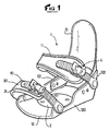
- Figure 1 is a general perspective view of clamping devices of the prior art suitable for a shell attachment for snowboarding.
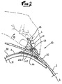
- Figure 2 is a side sectional view of a device of a device according to the prior art.
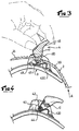
- Figure 3 is a view similar to the view of Figure 2 for a device according to the invention.
- Figure 4 is a partial sectional view along a plane offset from that of Figure 3 for a device according to the invention.
- the devices in question in the present application find their utility in the field of snowboard hull bindings including a specimen is shown as an example.
- the fastener 1 comprises two separate clamping devices 10, 11; one of them 10 used to tighten the end of a shoe (not shown) and the other 11 used to tighten the part of the instep of the shoe.
- the attachment comprises a base 12 on which is intended to rest the sole of the shoe; and which extends on the sides and upwards by lateral edges 120, 121 and at the rear by a rigid arch 122.
- a support element rear 13 is articulated on the edges 120, 121 and bears against the arch 122 to provide a rear support necessary for cornering on the rear edge of the board in particular.
- the device of the prior art which is illustrated by way of example and in detail in FIG. 2, includes a strap part 2 provided with a toothed portion 20 and a band to be tightened 3 on which is mounted a locking member 4.
- the part of strap 2 is fixedly attached to one of the side edges 120 of the binding, while that the strip 3 is fixedly attached to the opposite edge 121.
- the strip generally comprises an inextensible and flexible part 30 in plastic, fabric or leather and a padding portion 31 of fabric or foam to ensure comfort when tightening.
- the strap part is made of semi-rigid plastic so as to present a certain flexural strength while being able to conform to the domed shape of the shoe.
- the locking member 4 is provided with a base 42 fixed on the flap or the band 3.
- a pawl 41 is connected to the base by a hinge 43 and comprises a complementary toothed retaining portion 410 intended to cooperate with the portion toothed portion 20 of the strap portion 2.
- a torsion spring 44 holds the portions teeth 20, 410 in contact with each other in the locked position.
- the locking member comprises a lever 45 which can be actuated against the force exerted by the spring 44 for the disengagement of the toothed portions 20, 410.
- the engagement of the toothed strap part 2 is in the direction A indicated without manual lever action thanks in particular to the orientation of the teeth which allows rotation of the pawl and lifting of the portion of teeth 410.
- the engagement of the strap is stopped in a given locking position and any return of the strap in the opposite direction of A becomes impossible without manual action of the ratchet.
- Figure 2 therefore shows the manual disengagement operation which consists of act on lever 45 in the direction of rotation B indicated; which keeps them away toothed one of the other and allows the strap 2 to slide out of the locking.
- the torque exerted in direction B indicated promotes a reconciliation and recovery of the padded band 3 and the strap part 2.
- Figures 3 and 4 show the solution which is proposed by the invention for attempt to resolve this issue while retaining lock security on the device.
- the strap part 2 engages through the locking member in a space 411 formed between the articulation 43 and the complementary toothed retaining portion 410 of the pawl 41; the complementary toothed retaining portion 410 lying in relation to the articulation 43 on the engagement side of the strap part 2 in the locking 4 so that in the locking position, the tightening torque which is exerted by the pawl 41 on the toothed portion 20 increases in proportion to the tensile force exerted on the strap 2 in the direction of disengagement of the locking member 4.
- the action on the lever 45 is exerted in the direction of rotation C indicated, which in turn promotes the distance of the strip padded 3 with respect to the toothed strap 2.
- the base is provided with a boss 420 at the entrance to space 411 on the engagement side of the strap part.
- the means of elastic return 44 advantageously consists of a torsion spring 44 mounted on the axis of the articulation 43.
- One of the arms of the spring is integral with the base 42 while the other arm is attached to the pawl 41.
- the complementary retaining portion 410 of the pawl may include a variable number of teeth; the choice of two teeth as illustrated satisfies the compromise to be made between ensuring sufficient hooking and ease of disengagement.
- such a clamping device is particularly suitable to equip a snowboard binding but is not only limited to this use. It is conceivable that such a device is used for tightening a sports shoe for example.
- element 3 to be tightened can be different from a padded band. It can be a flap or flap, for example, any surface that can cover a large part of the foot.
Landscapes
- Footwear And Its Accessory, Manufacturing Method And Apparatuses (AREA)
- Clamps And Clips (AREA)
- Devices For Conveying Motion By Means Of Endless Flexible Members (AREA)
- Buckles (AREA)
Abstract
Description
L'invention concerne un dispositif de serrage par sangle dentée coopérant avec un organe de verrouillage à cliquet. Elle se rapporte plus particulièrement aux dispositifs de serrage pouvant équiper les fixations de surf de neige à sangles, les patins à roulette, patins en ligne, les chaussures de sport à tige souple ou semi-rigide telles que les bottes de surf de neige, les chaussures de randonnées, ou les chaussures de ski de fond, etc.The invention relates to a clamping device by toothed strap cooperating with a member. ratchet lock. It relates more particularly to clamping devices can be fitted to snowboard bindings with straps, roller skates, inline skates, sports shoes with flexible or semi-rigid upper such as snowboard boots, hiking boots, or cross-country ski boots, etc.
Dans les dispositifs du type énoncé, l'objectif est de pouvoir réaliser un serrage d'une bande ou d'un volet contre une surface généralement de forme courbe, en tissu ou autre matériau souple ; au moyen d'une sangle dentée qui s'engage par engrènement dans un cliquet solidaire de ladite bande ou dudit volet. Le desserrage de la bande ou du volet s'effectue par actionnement d'un levier qui libère la sangle dentée de la denture du cliquet.In devices of the stated type, the objective is to be able to tighten a strip or shutter against a generally curved, fabric or other surface flexible material; by means of a toothed strap which engages by engagement in a ratchet integral with said strip or said flap. The band or flap is loosened by actuation of a lever which releases the toothed strap from the teeth of the pawl.
Un exemple de dispositif est donné par le document AT-C-379297. Selon ce document, un dispositif de serrage comprend une sangle munie d'une portion dentée et une bande à serrer sur laquelle est monté un organe de verrouillage. Ce dernier comprend une embase fixée sur la bande et un cliquet relié à l'embase par deux articulations. La sangle s'engage entre le cliquet et l'embase pour permettre le serrage du dispositif.An example of a device is given by document AT-C-379297. According to this document, a tightening device comprises a strap provided with a toothed portion and a band to be tightened on which is mounted a locking member. The latter includes a base fixed to the band and a ratchet connected to the base by two joints. The strap engages between the pawl and the base to allow the tightening of the device.
Un inconvénient majeur des systèmes existants provient de ce qu'aucun n'apporte à la fois une sécurité de verrouillage suffisante et une libération rapide de la sangle en dehors de l'organe de verrouillage.A major drawback of existing systems is that none brings both sufficient locking security and rapid release of the strap outside the locking member.
En général, le couple exercé sur le levier est orienté dans la direction opposée au bout de la sangle dentée ce qui a tendance à favoriser l'engagement de la sangle dentée dans l'organe de verrouillage plutôt que son dégagement rapide et automatique.In general, the torque exerted on the lever is oriented in the opposite direction at the end of the toothed strap which tends to favor the engagement of the toothed strap in the locking rather than quick and automatic release.
Or, dans le cas d'une fixation de surf de neige ayant pour objet de retenir une botte souple sur une planche de glisse, par exemple, il est important de pouvoir rendre le desserrage des sangles plus rapide car cette opération se répète souvent lors de la pratique du surf et dans des conditions quelquefois difficiles.However, in the case of a snowboard binding intended to retain a flexible boot on a sliding board, for example, it is important to be able to make the loosening of the straps faster because this operation is often repeated when surfing and in sometimes difficult conditions.
Le but de la présente invention est donc d'apporter une solution satisfaisante aux problèmes rencontrés par les systèmes de l'art antérieur.The purpose of the present invention is therefore to provide a satisfactory solution to problems encountered by the systems of the prior art.
A cet effet, le dispositif de serrage de l'invention comprend une partie de sangle munie d'une portion dentée et un élément à serrer du type bande, volet ou rabat sur lequel est monté un organe de verrouillage comprenant :
- une embase fixée sur l'élément à serrer ;
- un cliquet relié à l'embase par une seule articulation et ayant au moins une portion dentée complémentaire de retenue destinée à coopérer avec la portion dentée de la partie de sangle ;
- un moyen de rappel élastique qui maintient les portions dentées en contact l'une de l'autre en position de verrouillage ;
- un levier solidaire du cliquet, le levier étant actionnable à l'encontre de la force exercée par le moyen de rappel élastique pour le désengagement des portions dentées,
- et un espace ménagé entre le cliquet et l'embase pour l'engagement de la partie de sangle sous la portion dentée du cliquet.
- a base fixed to the element to be clamped;
- a pawl connected to the base by a single articulation and having at least one complementary toothed retention portion intended to cooperate with the toothed portion of the strap part;
- elastic return means which keeps the toothed portions in contact with each other in the locked position;
- a lever secured to the pawl, the lever being actuable against the force exerted by the elastic return means for disengaging the toothed portions,
- and a space provided between the pawl and the base for the engagement of the strap part under the toothed portion of the pawl.
Le dispositif selon l'invention est caractérisé par le fait que l'espace est ménagé dans le cliquet entre l'articulation et la portion dentée pour le passage de la partie de sangle, et par le fait que la portion dentée et le levier sont situés par rapport à l'axe d'articulation d'un même côté d'engagement de la sangle.The device according to the invention is characterized in that the space is provided in the ratchet between the joint and the toothed portion for the passage of the strap portion, and by the fact that the toothed portion and the lever are located relative to the axis of articulation of the same strap engaging side.
Ainsi, en position de verrouillage, le couple de serrage qui s'exerce par le cliquet sur la portion dentée augmente proportionnellement à l'effort de traction exercée sur la sangle dans le sens du désengagement de l'organe de verrouillage. La conséquence est la garantie d'une sécurité du verrouillage quelque soient les efforts qui s'exercent sur le dispositif.Thus, in the locked position, the tightening torque exerted by the pawl on the toothed portion increases in proportion to the tensile force exerted on the strap in the direction of disengagement of the locking member. The consequence is the guarantee of a locking security whatever the forces exerted on the device.
De plus, le couple exercé manuellement sur le levier pour désengager les portions dentées entre elles, est dirigé dans une direction qui favorise la séparation de la bande ou volet par rapport à la sangle dentée. Il s'ensuit que la libération du dispositif est plus rapide et peut s'exercer d'une seule main par une simple action sur le levier.In addition, the torque exerted manually on the lever to disengage the toothed portions between them, is directed in a direction which promotes the separation of the strip or flap by compared to the toothed strap. It follows that the release of the device is faster and can exercise with one hand by a simple action on the lever.
La description suivante en référence aux dessins annexés permettra de mieux comprendre la présente invention.The following description with reference to the accompanying drawings will allow a better understanding the present invention.
La figure 1 est une vue générale en perspective de dispositifs de serrage de l'art antérieur adaptés sur une fixation à coque pour la pratique du surf de neige.Figure 1 is a general perspective view of clamping devices of the prior art suitable for a shell attachment for snowboarding.
La figure 2 est une vue en coupe latérale d'un dispositif d'un dispositif selon l'art antérieur.Figure 2 is a side sectional view of a device of a device according to the prior art.
La figure 3 est une vue similaire à la vue de la figure 2 pour un dispositif selon l'invention.Figure 3 is a view similar to the view of Figure 2 for a device according to the invention.
La figure 4 est vue en coupe partielle selon un plan décalé de celui de la figure 3 pour un dispositif selon l'invention.Figure 4 is a partial sectional view along a plane offset from that of Figure 3 for a device according to the invention.
Comme le montre la figure 1, les dispositifs dont il est question dans la présente demande trouvent leur utilité dans le domaine des fixations à coque de surf de neige dont un spécimen est représenté à titre d'exemple.As shown in Figure 1, the devices in question in the present application find their utility in the field of snowboard hull bindings including a specimen is shown as an example.
La fixation 1 comprend deux dispositifs de serrage séparés 10, 11 ; l'un d'eux 10 servant à
serrer le bout d'une chaussure (non représentée) et l'autre 11 servant à serrer la partie du coude-pied
de la chaussure. D'autre part, la fixation comprend une embase 12 sur laquelle est
destinée à reposer la semelle de la chaussure ; et qui se prolonge sur les côtés et vers le haut
par des bords latéraux 120, 121 et à l'arrière par un arceau rigide 122. Un élément d'appui
arrière 13 est articulé sur les bords 120, 121 et prend appui contre l'arceau 122 pour procurer
un support arrière nécessaire à la prise de virage sur la carre arrière de la planche notamment.The
Le dispositif de l'art antérieur 10, qui est illustré à titre d'exemple et en détail à la figure 2,
comprend une partie de sangle 2 munie d'une portion dentée 20 et d'une bande à serrer 3 sur
lequel est monté un organe de verrouillage 4. La partie de
sangle 2 est rattachée fixement à l'un des bords latéraux 120 de la fixation, tandis
que la bande 3 est rattachée fixement au bord opposé 121.The device of the
La bande comprend généralement une partie inextensible et flexible 30 en
plastique, tissu ou cuir et une partie de rembourrage 31 en tissu ou en mousse
pour assurer le confort lors du serrage.The strip generally comprises an inextensible and
La partie de sangle est réalisée en plastique semi-rigide de façon à présenter une certaine tenue en flexion tout en étant apte à se conformer à la forme bombée de la chaussure.The strap part is made of semi-rigid plastic so as to present a certain flexural strength while being able to conform to the domed shape of the shoe.
L'organe de verrouillage 4 est muni d'une embase 42 fixée sur le volet ou la
bande 3. Un cliquet 41 est relié à l'embase par une articulation 43 et comprend une
portion dentée complémentaire de retenue 410 destinée à coopérer avec la portion
dentée 20 de la partie de sangle 2. Un ressort de torsion 44 maintient les portions
dentées 20, 410 en contact l'une de l'autre en position de verrouillage. Enfin,
l'organe de verrouillage comprend un levier 45 qui est actionnable à l'encontre de
la force exercée par le ressort 44 pour le désengagement des portions dentées 20,
410.The locking member 4 is provided with a
L'engagement de la partie de sangle dentée 2 se fait dans le sens A indiqué
sans action manuelle du levier grâce notamment à l'orientation des dents qui
permet une rotation du cliquet et un soulèvement de la portion de dents 410.
Lorsque le serrage est suffisant, on stoppe l'engagement de la sangle dans une
position de verrouillage donnée et tout retour de la sangle dans le sens inverse de
A devient impossible sans action manuelle du cliquet.The engagement of the
La figure 2 montre donc l'opération manuelle de désengagement qui consiste à
agir sur le levier 45 dans le sens de rotation B indiqué ; ce qui éloigne les partie
dentées l'une de l'autre et permet le glissement de la sangle 2 hors de l'organe de
verrouillage. Comme il apparaít sur la figure 2, le couple exercé dans le sens B
indiqué favorise un rapprochement et un recouvrement de la bande rembourrée 3
et de la partie de sangle 2. En pratique, on s'aperçoit donc qu'il est difficile de
pratiquer au déchaussage par une simple action du levier et qu'il est nécessaire de
tirer la partie de sangle dentée hors de l'organe de verrouillage en utilisant l'autre
main.Figure 2 therefore shows the manual disengagement operation which consists of
act on
Les figures 3 et 4 montrent la solution qui est proposée par l'invention pour tenter de résoudre ce problème tout en conservant une sécurité de verrouillage du dispositif.Figures 3 and 4 show the solution which is proposed by the invention for attempt to resolve this issue while retaining lock security on the device.
Comme le dispositif de l'art antérieur, le dispositif de l'invention comprend une partie de sangle 2 munie d'une portion dentée 20 et d'une bande à serrer 3 sur lequel est monté un organe de verrouillage 4 comprenant
- une
embase 42 fixée sur labande 3 ; - un cliquet 4 relié à l'embase par une
articulation 43 et ayant au moins une portion dentée complémentaire deretenue 410 destinée à coopérer avec la portion dentée 20 de la partie desangle 2 ; - un moyen de rappel élastique 44 qui maintient les portions dentées 20, 410 en contact l'une de l'autre en position de verrouillage et ;
- un
levier 45 actionnable à l'encontre de la force exercée par le moyen de rappel élastique 44 pour le désengagement des portions dentées 20, 410.
- a
base 42 fixed to thestrip 3; - a pawl 4 connected to the base by a
hinge 43 and having at least one complementarytoothed retaining portion 410 intended to cooperate with thetoothed portion 20 of thestrap part 2; - an elastic return means 44 which keeps the
toothed portions - a
lever 45 actuable against the force exerted by the elastic return means 44 for the disengagement of thetoothed portions
Selon une caractéristique essentielle de l'invention, la partie de sangle 2
s'engage au travers de l'organe de verrouillage dans un espace 411 ménagé entre
l'articulation 43 et la portion dentée complémentaire de retenue 410 du cliquet 41 ;
la portion dentée complémentaire de retenue 410 se situant par rapport à
l'articulation 43 du côté d'engagement de la partie de sangle 2 dans l'organe de
verrouillage 4 de façon qu'en position de verrouillage, le couple de serrage qui
s'exerce par le cliquet 41 sur la portion dentée 20 augmente proportionnellement à
l'effort de traction exercée sur la sangle 2 dans le sens du désengagement de
l'organe de verrouillage 4. Ainsi également, l'action sur le levier 45 s'exerce dans
le sens de rotation C indiqué qui, quant à lui favorise l'éloignement de la bande
rembourrée 3 par rapport à la sangle dentée 2.According to an essential characteristic of the invention, the
Afin de faciliter l'introduction de l'extrémité 21 de la partie de sangle 2 dans
l'espace 411 de l'organe de verrouillage 4, l'embase est munie d'un bossage 420
à l'entrée de l'espace 411 du côté d'engagement de la partie de sangle.In order to facilitate the introduction of the
Comme le montre la figure 4, pour un encombrement minimal, le moyen de
rappel élastique 44 est avantageusement constitué d'un ressort de torsion 44
monté sur l'axe de l'articulation 43. L'un des bras du ressort est solidaire de
l'embase 42 alors que l'autre bras est rattaché sur le cliquet 41.As shown in Figure 4, for a minimum footprint, the means of
La portion de retenue complémentaire 410 du cliquet peut comprendre un
nombre variable de dents ; le choix de deux dents tel qu'illustré satisfait au
compromis à réaliser entre l'assurance d'un accrochage suffisant et une facilité de
désengagement.The
Comme expliqué précédemment, un tel dispositif de serrage est particulièrement
adapté pour équiper une fixation de surf de neige mais n'est pas uniquement limité
à cette utilisation. On peut envisager qu'un tel dispositif serve au serrage d'une
chaussure de sport par exemple. Dans ce cas, l'élément 3 à serrer peut être
différent d'une bande rembourrée. Il peut s'agir d'un volet ou rabat, par exemple,
de surface quelconque pouvant recouvrir une partie importante du pied.As explained above, such a clamping device is particularly
suitable to equip a snowboard binding but is not only limited
to this use. It is conceivable that such a device is used for tightening a
sports shoe for example. In this case,
Les matériaux et le nombre des composants pour l'exécution des différents éléments sont des paramètres laissés à l'appréciation de l'homme du métier en fonction des besoins spécifiques en terme d'encombrement, résistance, durabilité, poids, etc.The materials and the number of components for the execution of the different elements are parameters left to the appreciation of a person skilled in the art in according to specific needs in terms of space, resistance, durability, weight, etc.
Claims (6)
- Tightening device including a strap portion (2) provided with a serrated portion (20) and with a tightening element (3), such as a belt, band or flap, on which is mounted a locking member (4) including:characterized in that the space (411) is provided in the ratchet (41) between the journal (43) and the serrated portion (410) for the passage of the strap portion (2), and in that the serrated portion (410) and the lever (45) are located with respect to the journal axis (43) of a same side of engagement of the strap.a base (42) fixed on the tightening element (3),a ratchet (41) connected to the base by a single journal (43) and having at least one complementary retaining serrated portion (410) adapted to cooperate with the serrated portion (20) of the strap portion (2),an elastic return device (44) which maintains the serrated portions (20, 410) in contact with one another in the locking position,a lever (45) integral with the ratchet (41), the lever (45) can be actuated against the force exerted by the elastic return device (44) for disengaging the serrated portions (20,410),and a space provided between the ratchet and the base for engaging the strap portion under the serrated portion (410) of the ratchet,
- Tightening device according to claim 1, characterized in that the base (42) is provided with a boss (420) at the inlet of the space (411) on the side where the strap portion (2) engages to introduce the end (21) of the strap portion in the space (411).
- Tightening device according to claim 1 or 2, characterized in that the elastic return device (44) is a torsional spring mounted on the journal axis (43).
- Snowboard binding, characterized in that it includes at least one tightening device according to any one of the preceding claims for retaining a boot on a board.
- Snowboard binding according to claim 4, including:a base (12) on which the sole of a boot is adapted to rest, and which is extended sideward and upward by lateral edges (120, 121), and rearward by a rigid arch (122), the strap portion (2) of the tightening device being fixedly attached to one of the lateral edges (120) of the binding, while the band (3) is fixedly attached to the opposing edge (121),a rear support element (13) journalled on the edges (120, 121) and taking support against the arch (122) to provide a rear support.
- Sport boot characterized in that it includes a tightening device according to any one of claims 1-3 for tightening the foot in the boot.
Applications Claiming Priority (2)
| Application Number | Priority Date | Filing Date | Title |
|---|---|---|---|
| FR9607595A FR2749738B1 (en) | 1996-06-13 | 1996-06-13 | DEVICE FOR CLAMPING WITH A TOOTHED STRAP AND RATCHET LOCKING MEMBER |
| FR9607595 | 1996-06-13 |
Publications (2)
| Publication Number | Publication Date |
|---|---|
| EP0812552A1 EP0812552A1 (en) | 1997-12-17 |
| EP0812552B1 true EP0812552B1 (en) | 2002-02-06 |
Family
ID=9493190
Family Applications (1)
| Application Number | Title | Priority Date | Filing Date |
|---|---|---|---|
| EP97107851A Expired - Lifetime EP0812552B1 (en) | 1996-06-13 | 1997-05-14 | Tightening device with serrated strap and ratchet lock |
Country Status (5)
| Country | Link |
|---|---|
| US (1) | US5852852A (en) |
| EP (1) | EP0812552B1 (en) |
| AT (1) | ATE212802T1 (en) |
| DE (1) | DE69710255T2 (en) |
| FR (1) | FR2749738B1 (en) |
Cited By (1)
| Publication number | Priority date | Publication date | Assignee | Title |
|---|---|---|---|---|
| US6416074B1 (en) | 1999-06-15 | 2002-07-09 | The Burton Corporation | Strap for a snowboard boot, binding or interface |
Families Citing this family (40)
| Publication number | Priority date | Publication date | Assignee | Title |
|---|---|---|---|---|
| JP3665946B2 (en) * | 1998-02-12 | 2005-06-29 | 株式会社カーメイト | Snowboard binding |
| EP0958846A1 (en) * | 1998-05-20 | 1999-11-24 | Samuel Hunziker | Removable clamping device of a shoe on a sports implement |
| TW368805U (en) * | 1998-08-27 | 1999-09-01 | Taiwan Ind Fastener Corp | Adjustable fastener |
| US6052924A (en) * | 1998-10-13 | 2000-04-25 | Sabat; Jack M. | Variable weight athletic shoe |
| US6267390B1 (en) * | 1999-06-15 | 2001-07-31 | The Burton Corporation | Strap for a snowboard boot, binding or interface |
| US6298640B1 (en) * | 1999-08-17 | 2001-10-09 | John R. Schneider | Grab saddle system |
| US6526629B1 (en) * | 2000-01-28 | 2003-03-04 | Tubbs Snowshoe Company Llc | Showshoe with cam lock buckle |
| FR2806923B1 (en) * | 2000-04-03 | 2002-11-29 | Salomon Sa | SLIDING CLAMP FOR SPORTS GOODS |
| US6412794B1 (en) | 2000-11-01 | 2002-07-02 | The Burton Corporation | Fastening assembly and method for securing footwear to a binding |
| US6341382B1 (en) | 2000-11-06 | 2002-01-29 | Jackson Products, Inc. | One-piece adjustable headgear support |
| US6554297B2 (en) | 2001-01-03 | 2003-04-29 | The Burton Corporation | Dive resistant buckle |
| DE20100469U1 (en) * | 2001-01-11 | 2001-03-29 | Neil Pryde Ltd., Tuen Mun, New Territories | Quick-release belt locking device |
| FR2820049B1 (en) * | 2001-01-31 | 2003-03-21 | Salomon Sa | DEVICE FOR RETAINING A SHOE ON A SPORTS MACHINE |
| NL1017836C2 (en) * | 2001-04-12 | 2002-10-15 | Orang Tiga N V | Trouser belt. |
| FR2827185B1 (en) * | 2001-07-16 | 2003-09-05 | Rossignol Sa | DEVICE INTENDED TO ENSURE THE TIGHTENING OF TWO PARTS OF A SPORTS ARTICLE |
| FR2838978B1 (en) * | 2002-04-30 | 2004-05-28 | Emery Sa | SNOW SURF FIXING |
| AU154957S (en) | 2002-12-06 | 2004-03-17 | Resmed Ltd | A clip |
| US6898826B2 (en) | 2003-01-06 | 2005-05-31 | K-2 Corporation | Co-molded ladder strap |
| US20060175802A1 (en) * | 2005-01-07 | 2006-08-10 | Rome Snowboards, Corp. | Snowboard impact plate and binding release mechanism |
| US7887082B2 (en) | 2006-09-01 | 2011-02-15 | Wire Core Strap, Inc. | Reformable closure device strap |
| FR2910338B1 (en) * | 2006-12-20 | 2009-06-05 | Salomon Sa | ARTICLE COMPRISING A RETAINING OR CLAMPING LINK ON A FOOT OR SHOE |
| FR2915905A1 (en) * | 2007-05-11 | 2008-11-14 | Rossignol Sa | DEVICE FOR ADJUSTING SPATULA OF A SLIDING BOARD |
| US20100125986A1 (en) * | 2008-11-25 | 2010-05-27 | Armstrong Richard W | Locking Mechanism for A Tie Down |
| USD636983S1 (en) | 2009-06-05 | 2011-05-03 | Dashamerica, Inc. | Cycling shoe |
| USD630419S1 (en) | 2009-06-05 | 2011-01-11 | Dashamerica, Inc. | Base plate for adjustable strap |
| USD611237S1 (en) | 2009-06-05 | 2010-03-09 | Dashamerica, Inc. | Cycling shoe insole |
| US9127486B2 (en) | 2010-01-25 | 2015-09-08 | Vision Industries Group, Inc. | Sash window and door transportation clip assembly |
| US8333433B2 (en) * | 2010-02-10 | 2012-12-18 | Friedman Mark J | Locking harness apparatus and method |
| CA2807203C (en) * | 2010-08-09 | 2018-06-19 | Benrikal Services Inc. | Lockable attachment and styptic device including same |
| US8627551B2 (en) * | 2011-08-18 | 2014-01-14 | Hsin-Hsiang TSENG | Segment positioning belt |
| US8763209B2 (en) | 2011-08-23 | 2014-07-01 | The Burton Corporation | Ratchet buckle and strap assembly |
| CN104093333B (en) * | 2011-11-04 | 2017-06-30 | 布里格斯及莱利旅行用品有限责任公司 | For the ratchet type extender system of luggage case |
| WO2014165856A2 (en) | 2013-04-05 | 2014-10-09 | Thinline, Llc | Asymmetrically releasable fastener system and cuff for use therewith |
| WO2015073787A1 (en) | 2013-11-15 | 2015-05-21 | S. C. Johnson & Son, Inc. | Apparatus to retain a cleaning implement |
| US9566499B2 (en) * | 2015-02-07 | 2017-02-14 | Daniel C. Sullivan | Binding strap assist mechanism with a torsion spring |
| US10618730B2 (en) * | 2015-03-02 | 2020-04-14 | Grigooris MANSSOURIAN | Retainer mechanism |
| US9656591B1 (en) | 2015-08-27 | 2017-05-23 | Jayson Dumenigo | Securing strap having at least one strap securing interface |
| CN112237732A (en) * | 2019-07-18 | 2021-01-19 | 武汉酷雪体育用品有限公司 | Skis |
| USD923510S1 (en) * | 2020-03-25 | 2021-06-29 | Easyrig AB | Buckle |
| US20240263498A1 (en) * | 2023-02-07 | 2024-08-08 | Brayden Hunter | Portable Door Lock |
Family Cites Families (9)
| Publication number | Priority date | Publication date | Assignee | Title |
|---|---|---|---|---|
| FR1204470A (en) * | 1958-04-02 | 1960-01-26 | Improvements to devices intended to temporarily assemble straps to one another, in particular to belt buckles fitted to vehicle seats | |
| US3253309A (en) * | 1963-11-29 | 1966-05-31 | Charles A Baresch | Buckle assembly |
| SE357665B (en) * | 1968-03-21 | 1973-07-09 | Bengtsson Sigurd W | |
| IT8120472U1 (en) * | 1981-01-14 | 1982-07-14 | Olivieri Icaro & C | Quick lacing for roller skates |
| AT379297B (en) * | 1983-12-15 | 1985-12-10 | Dynafit Gmbh | LOCKING OF TWO PARTS, ESPECIALLY TWO SHOES |
| IT8451902U1 (en) * | 1984-04-11 | 1985-10-11 | Tecnosky S N C | Ratchet for fastening the toothed strap for ski boots with self-locking by means of a loop and undercut |
| IT8409513U1 (en) * | 1984-05-08 | 1985-11-08 | Biavaschi Ciapusci Ilde | Lockable harpoon safety anchor for ski boot tightening toothed strap |
| US5480176A (en) * | 1994-01-18 | 1996-01-02 | Sims; Thomas P. | External mounted binding |
| US5416952A (en) * | 1994-01-27 | 1995-05-23 | Burton Snowboards | Ratchet-type buckle |
-
1996
- 1996-06-13 FR FR9607595A patent/FR2749738B1/en not_active Expired - Fee Related
-
1997
- 1997-05-14 DE DE69710255T patent/DE69710255T2/en not_active Expired - Lifetime
- 1997-05-14 AT AT97107851T patent/ATE212802T1/en not_active IP Right Cessation
- 1997-05-14 EP EP97107851A patent/EP0812552B1/en not_active Expired - Lifetime
- 1997-06-09 US US08/871,667 patent/US5852852A/en not_active Expired - Fee Related
Cited By (1)
| Publication number | Priority date | Publication date | Assignee | Title |
|---|---|---|---|---|
| US6416074B1 (en) | 1999-06-15 | 2002-07-09 | The Burton Corporation | Strap for a snowboard boot, binding or interface |
Also Published As
| Publication number | Publication date |
|---|---|
| DE69710255T2 (en) | 2002-08-14 |
| FR2749738B1 (en) | 1998-09-11 |
| FR2749738A1 (en) | 1997-12-19 |
| ATE212802T1 (en) | 2002-02-15 |
| EP0812552A1 (en) | 1997-12-17 |
| US5852852A (en) | 1998-12-29 |
| DE69710255D1 (en) | 2002-03-21 |
Similar Documents
| Publication | Publication Date | Title |
|---|---|---|
| EP0812552B1 (en) | Tightening device with serrated strap and ratchet lock | |
| EP1596948B1 (en) | Binding for keeping a boot attached to a snowboard | |
| EP1512440B1 (en) | Fastening device for a boot or a shoe on a sporting good | |
| FR2746604A1 (en) | DEVICE FOR RETAINING A SHOE ON A BOARD WITH ARTICULATED BACK SUPPORT MEMBER | |
| EP1147791B1 (en) | Snowboard or skateboard boot binding | |
| FR2472920A2 (en) | ADJUSTABLE DYNAMIC UPPER SPORTS SHOE | |
| FR2627097A1 (en) | Bindings for a snowboard | |
| FR2731323A1 (en) | Ski boot and ski bindings | |
| FR2732230A1 (en) | Semi-automatic fastener holding boot on snow board | |
| FR3106039A1 (en) | Shoe clamp | |
| EP1277414A1 (en) | Apparatus for tightening two parts of an sport article | |
| EP1062992B1 (en) | Fixation device for a snow sporting good | |
| EP1358916B1 (en) | A sport shoe for practising a gliding sport or snowboard binding with snap fastener flaps | |
| EP1118360A1 (en) | Retaining device for a boot to a sport article | |
| EP0956886B1 (en) | Interface between a boot and a snowboard | |
| EP1050325A1 (en) | Device for holding a boot on a snowboard | |
| EP1327467A1 (en) | Device for retaining a shoe to a sporting article | |
| EP1358917B1 (en) | Snowboard binding | |
| EP2322255B1 (en) | Braking device for a snowboard | |
| FR3071134B1 (en) | SKI SHOE WITH SIMPLICITY OF IMPROVED USE | |
| FR3099346A1 (en) | Sports shoe able to cooperate with a binding device attached to a gliding board | |
| EP1825772A1 (en) | Fastener device for a sports shoe | |
| FR2829943A1 (en) | Snowboard boot fixing comprises base and strap fixed to base which receives boot front and rear support shell hinged to base receiving boot rear part | |
| EP0335047A1 (en) | Boot with laces | |
| FR2749520A1 (en) | Strap in two parts holding boot on snow-board |
Legal Events
| Date | Code | Title | Description |
|---|---|---|---|
| PUAI | Public reference made under article 153(3) epc to a published international application that has entered the european phase |
Free format text: ORIGINAL CODE: 0009012 |
|
| AK | Designated contracting states |
Kind code of ref document: A1 Designated state(s): AT CH DE FR IT LI |
|
| 17P | Request for examination filed |
Effective date: 19980604 |
|
| 17Q | First examination report despatched |
Effective date: 20000605 |
|
| GRAG | Despatch of communication of intention to grant |
Free format text: ORIGINAL CODE: EPIDOS AGRA |
|
| GRAG | Despatch of communication of intention to grant |
Free format text: ORIGINAL CODE: EPIDOS AGRA |
|
| GRAH | Despatch of communication of intention to grant a patent |
Free format text: ORIGINAL CODE: EPIDOS IGRA |
|
| GRAH | Despatch of communication of intention to grant a patent |
Free format text: ORIGINAL CODE: EPIDOS IGRA |
|
| GRAA | (expected) grant |
Free format text: ORIGINAL CODE: 0009210 |
|
| AK | Designated contracting states |
Kind code of ref document: B1 Designated state(s): AT CH DE FR IT LI |
|
| PG25 | Lapsed in a contracting state [announced via postgrant information from national office to epo] |
Ref country code: IT Free format text: LAPSE BECAUSE OF FAILURE TO SUBMIT A TRANSLATION OF THE DESCRIPTION OR TO PAY THE FEE WITHIN THE PRE;WARNING: LAPSES OF ITALIAN PATENTS WITH EFFECTIVE DATE BEFORE 2007 MAY HAVE OCCURRED AT ANY TIME BEFORE 2007. THE CORRECT EFFECTIVE DATE MAY BE DIFFERENT FROM THE ONE RECORDED.SCRIBED TIME-LIMIT Effective date: 20020206 Ref country code: AT Free format text: LAPSE BECAUSE OF FAILURE TO SUBMIT A TRANSLATION OF THE DESCRIPTION OR TO PAY THE FEE WITHIN THE PRESCRIBED TIME-LIMIT Effective date: 20020206 |
|
| REF | Corresponds to: |
Ref document number: 212802 Country of ref document: AT Date of ref document: 20020215 Kind code of ref document: T |
|
| REG | Reference to a national code |
Ref country code: CH Ref legal event code: EP |
|
| REF | Corresponds to: |
Ref document number: 69710255 Country of ref document: DE Date of ref document: 20020321 |
|
| PG25 | Lapsed in a contracting state [announced via postgrant information from national office to epo] |
Ref country code: LI Free format text: LAPSE BECAUSE OF NON-PAYMENT OF DUE FEES Effective date: 20020531 Ref country code: CH Free format text: LAPSE BECAUSE OF NON-PAYMENT OF DUE FEES Effective date: 20020531 |
|
| PLBE | No opposition filed within time limit |
Free format text: ORIGINAL CODE: 0009261 |
|
| STAA | Information on the status of an ep patent application or granted ep patent |
Free format text: STATUS: NO OPPOSITION FILED WITHIN TIME LIMIT |
|
| REG | Reference to a national code |
Ref country code: CH Ref legal event code: PL |
|
| 26N | No opposition filed |
Effective date: 20021107 |
|
| REG | Reference to a national code |
Ref country code: FR Ref legal event code: CJ Ref country code: FR Ref legal event code: CA |
|
| PGFP | Annual fee paid to national office [announced via postgrant information from national office to epo] |
Ref country code: FR Payment date: 20100525 Year of fee payment: 14 |
|
| PGFP | Annual fee paid to national office [announced via postgrant information from national office to epo] |
Ref country code: DE Payment date: 20100512 Year of fee payment: 14 |
|
| REG | Reference to a national code |
Ref country code: DE Ref legal event code: R119 Ref document number: 69710255 Country of ref document: DE |
|
| REG | Reference to a national code |
Ref country code: DE Ref legal event code: R119 Ref document number: 69710255 Country of ref document: DE |
|
| REG | Reference to a national code |
Ref country code: FR Ref legal event code: ST Effective date: 20120131 |
|
| PG25 | Lapsed in a contracting state [announced via postgrant information from national office to epo] |
Ref country code: FR Free format text: LAPSE BECAUSE OF NON-PAYMENT OF DUE FEES Effective date: 20110531 |
|
| PG25 | Lapsed in a contracting state [announced via postgrant information from national office to epo] |
Ref country code: DE Free format text: LAPSE BECAUSE OF NON-PAYMENT OF DUE FEES Effective date: 20111130 |