EP1277414B1 - Spanneinrichtung für zwei Teile eines Sportgerätes - Google Patents
Spanneinrichtung für zwei Teile eines Sportgerätes Download PDFInfo
- Publication number
- EP1277414B1 EP1277414B1 EP02356123A EP02356123A EP1277414B1 EP 1277414 B1 EP1277414 B1 EP 1277414B1 EP 02356123 A EP02356123 A EP 02356123A EP 02356123 A EP02356123 A EP 02356123A EP 1277414 B1 EP1277414 B1 EP 1277414B1
- Authority
- EP
- European Patent Office
- Prior art keywords
- guide
- tongue
- complementary piece
- walls
- complementary
- Prior art date
- Legal status (The legal status is an assumption and is not a legal conclusion. Google has not performed a legal analysis and makes no representation as to the accuracy of the status listed.)
- Expired - Lifetime
Links
Images


Classifications
-
- A—HUMAN NECESSITIES
- A43—FOOTWEAR
- A43C—FASTENINGS OR ATTACHMENTS OF FOOTWEAR; LACES IN GENERAL
- A43C11/00—Other fastenings specially adapted for shoes
- A43C11/14—Clamp fastenings, e.g. strap fastenings; Clamp-buckle fastenings; Fastenings with toggle levers
- A43C11/1406—Fastenings with toggle levers; Equipment therefor
- A43C11/1413—Equipment for fastening toggle lever fastenings
-
- A—HUMAN NECESSITIES
- A63—SPORTS; GAMES; AMUSEMENTS
- A63C—SKATES; SKIS; ROLLER SKATES; DESIGN OR LAYOUT OF COURTS, RINKS OR THE LIKE
- A63C10/00—Snowboard bindings
- A63C10/02—Snowboard bindings characterised by details of the shoe holders
- A63C10/04—Shoe holders for passing over the shoe
-
- A—HUMAN NECESSITIES
- A63—SPORTS; GAMES; AMUSEMENTS
- A63C—SKATES; SKIS; ROLLER SKATES; DESIGN OR LAYOUT OF COURTS, RINKS OR THE LIKE
- A63C10/00—Snowboard bindings
- A63C10/02—Snowboard bindings characterised by details of the shoe holders
- A63C10/04—Shoe holders for passing over the shoe
- A63C10/06—Straps therefor, e.g. adjustable straps
-
- A—HUMAN NECESSITIES
- A63—SPORTS; GAMES; AMUSEMENTS
- A63C—SKATES; SKIS; ROLLER SKATES; DESIGN OR LAYOUT OF COURTS, RINKS OR THE LIKE
- A63C10/00—Snowboard bindings
- A63C10/24—Calf or heel supports, e.g. adjustable high back or heel loops
Definitions
- the invention relates to the field of sporting goods, and in particular to sliding sports. It is more particularly a clamping device used on sports articles such as snowboard bindings, ski boots, roller skates or harnesses. It relates more specifically to a particular geometry of certain mechanisms using toothed tongues, and whose configuration facilitates the use.
- the invention is more particularly described in its application to snowboarding, but it can also be transposed for various other sports articles using clamping systems similar to those used on snowboard bindings. .
- Some surf bindings commonly referred to as “hull fasteners” have straps that pass over the foot so as to keep it clamped into the binding. These straps are generally adjustable in length to adapt to all shoe configurations.
- An example of this type of strap is described in WO 97/28859. These straps comprise two parts, namely a first part formed by a rectilinear notched tongue which is fixed on one side of the fastener. On the other side of the binding, the strap includes a portion passing over the foot, and ending with a ratchet system.
- the rectilinear tongue is placed between the walls of a guide on which is articulated a pawl.
- This pawl cooperates with the notches of the notched tongue to prevent the strap from loosening.
- the walls of the guide are spaced a distance equal to the width of the notched tongue, to avoid any mechanical play, and prevent the latter from moving laterally in the guide.
- a problem to be solved by the invention is that of the compatibility between an absence of lateral play of the tongue inside the guide, and ease of implementation of the tongue in the guide.
- EP-A-1 203 540 forms part of the state of the art under Article 54 (3) and (4) EPC.
- the invention therefore relates to a device for clamping two parts of a sports article.
- the device is characterized in that it also comprises a complementary piece in which is embedded the guide, the portion of the complementary piece located on the side of the opening of the guide through which the tongue is inserted, comprising two diverging walls flaring and extending beyond the opening of the guide.
- the device which ensures the locking of the tongue comprises a centering piece, a portion of which forms a tongue insertion opening, having a width substantially greater than the opening of the guide itself.
- the diverging walls of the complementary piece are extended by side walls facing the walls of the guide.
- the complementary piece envelops the underside of the guide and covers the lateral faces of the latter.
- This complementary piece may for example be made by overmoulding on the guide which may be metallic.
- centering means may for example be formed of a lug and a corresponding light, located on the guide and the complementary light.
- This locking of the guide relative to the complementary piece can be further improved in the case where the walls of the guide are extended by divergent walls coming into contact with a portion of the inner faces of the diverging walls of the complementary piece.
- the parallel side walls of the latter may slightly flake and come to fit partially in the diverging walls of the complementary piece. In this configuration, any relative movement of the guide and the complementary piece is prohibited.
- the side walls of the complementary piece can form gripping zones of the guide.
- the maneuvers of the pawl and other moving parts associated with the guide can be facilitated by effective handling of the complementary part, and therefore the guide.
- the outer faces of the side walls of the complementary part are then ergonomically configured, to allow the registration of the fingers of the user.
- the two side walls of the complementary piece are asymmetrical.
- the two gripping zones present on either side of the guide are not at the same longitudinal level of the complementary part, but are on the contrary offset, to accommodate the difference in length between thumb and forefinger
- the gripping zone intended to receive the support of the index is closer to the opening of the guide than that intended to receive the support of the thumb.
- the guide may comprise a lever cooperating with the tongue to cause the advancement in the guide.
- this additional lever when actuated, pushes the tongue inside the guide thus increasing the clamping.
- the ratchet meanwhile ensures the locking of the tongue by not opposing its advance in the guide, but preventing the recoil.
- the tongue is associated with an articulated loop, which is integral with the tongue and which ensures the displacement of the latter inside the guide, when actuated by the user.
- this articulated loop causes the displacement of the tongue in the direction of insertion, which allows it to penetrate the guide and cooperate with the pawl.
- the user folds the loop or more generally the maneuver it exerts a pull of the tongue in the opposite direction of its introduction into the guide. This movement is thwarted by the ratchet, which ensures tightening.
- the guide and the ratchet are associated with a loop. Maneuvering the loop moves the guide and the complementary piece towards the tongue which is fixed.
- the complementary and characteristic part of the invention can be an integral part of a new design locking system, or even be reported under the guide of an existing system, so as to improve the operation of the latter.
- the clamping device according to the invention can find a particularly advantageous application for equipping surf bindings.
- the device is mounted to ensure the tightening of the two parts of a strap.
- the device according to the invention can also be mounted on a gliding sports shoe such as an alpine ski boot, a cross-country ski boot, a surf boot or the like as well as a roller skate or a skateboard. ice skating.
- the device serves to clamp between them two flaps of the shoe, a first flap carrying the tongue, the other flap carrying the guide and the characteristic complementary piece.
- the invention relates to a clamping device which can find a particular application in sliding sports, and in particular for ski boots and surf bindings.
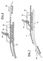
- the invention makes it possible to equip a fastener (1) of the "shell" type which comprises a base (2), a rear shell (3), and two straps (4, 5), connecting the two sides of the base (2), passing respectively above the instep and above the metatarsophalangeal joint.
- Each of these straps (4, 5) comprises a rectilinear notched tongue (6, 7) which is secured by one end (8, 9) to one side of the base.
- the other part of the strap (10, 11) is secured to the other side of the base.
- This portion (10, 11) which passes over the shoe is generally enlarged and padded to distribute the pressure it exerts on the shoe, and prevent it hurts the user.
- this portion of the strap (10, 11) comprises a clamping mechanism (12, 13) made according to the invention.
- This clamping device (12, 13) can be of different designs, as illustrated in FIG. 1.
- these locking mechanisms (12, 13) comprise a guide in which the notched tongue (6, 7) slides, and a ratchet system, which cooperates with the tongue (6, 7) to prevent sliding within the guide, in a direction that would loosen the strap.
- the clamping mechanism also comprises a lever (50) which cooperates with the tongue (6) to cause the advancement inside the guide, in the direction tightening.
- This additional lever (50) which may be advantageous, is however not necessary for the implementation of the invention.
- FIG. 3 The various elements forming the clamping mechanism are illustrated separately in FIG. 3.
- This joining can for example be carried out by a rivet (18) passing through a bore (31) formed in the guide (30) and a bore (21) formed in the central portion (22) of the complementary piece (20), as well as a bore (19) formed in the strap (12).
- the complementary piece (20) comprises a central portion (22), two side walls (23, 24) located on either side of the central portion (22). These side walls (23, 24) are extended at the front by diverging walls (25, 26) which flare away from the body of the workpiece (20).
- the complementary piece (20) On each outer face of the side walls (23, 24), the complementary piece (20) comprises a gripping zone (27, 28), slightly outgrowth.
- the shape of these gripping areas is determined by ergonomic considerations.
- One of the two gripping areas (27, 28) may be offset longitudinally relative to the other, to account for the difference in positioning of the thumb and index finger when the workpiece (20) is grasped by the user.
- the central portion (22) of the complementary piece (20) comprises a slight recess, delimited by the extra thickness (29), within which is embedded the guide (30).
- the guide (30) also comprises a central zone (32) to take place in the recess of the complementary piece (20).
- the guide (30) comprises side walls (33), which are flat and parallel. Near the opening (34) of the guide, these side walls (33) have an extension (35) away from the side wall (33) to the outside. These extension portions (35) are embedded in a portion of the diverging walls (25, 26) of the complementary piece (20).
- the two side walls (33) of the guides (30) are each pierced by a pair of openings (36, 37) receiving the axes (41, 51) respectively of the pawl (40) and the lever (50).
- the guide (30) has a cutout for forming a lug (38) deformed downwards, to fit into an opening (39) provided for this purpose in the complementary piece (20). In this way, the centering and locking of the guide (30) inside the complementary piece (20) are ensured.
- the guide (30) therefore receives, as shown in Figure 3, the pawl (40) ensuring the locking of the tongue (6) within the guide (30).
- the pawl (40) has an edge (42) which is embedded in a notch of the tongue (6). Pressure on the support zone (43) of the pawl (40) ensures pivoting of the latter and disengagement of the edge (42) of the notch of the tongue (6). This maneuver therefore allows the loosening of the strap.
- the width ⁇ 1 of the tongue is substantially equal to the distance ( ⁇ 2 ) which separates the internal faces of the walls (33) of the guide (30). In this way, the guidance of the tongue is carried out almost without any transverse play, and therefore no inaccuracy in tightening.
- the width L of the complementary part, measured at its opening, between the diverging walls (25, 26) is clearly greater than the width ⁇ 1 of the tongue (6), so that, even if the tongue is not presented in the axis of the guide (30), it is automatically folded in the right direction by the diverging walls (25, 26) characteristics.
- the invention is not limited to the use of a lever causing the advancement of the tongue inside the locking mechanism, but also covers other variants in which the guide (30) and the complementary piece (20) have only one locking pawl.
- the advance of the tongue can be caused in different ways.
- the tongue (6) can be associated with an articulated loop (60), located at its end connecting to the base of the fastener.
- the operation of the loop (60) causes the extension of the tongue (6) and its introduction into the guide (30).
- the reverse operation of the loop (60) causes a pull on the tongue, and therefore on the entire guide and the complementary piece when the pawl comes into action.
- the strap (12) which supports the guide (30) and the complementary piece (20) which is associated with a deformable loop (62).
- this loop (62) when this loop (62) is operated, the guide (30) and the complementary piece (20) are moved towards the tongue (6), causing the penetration of the latter in the guide (30).
- the reverse operation of the loop ensures traction on the strap (12), and therefore on the guide (30) and the pawl (40). When it comes into action, it ensures traction on the tongue (6), and therefore a tightening of the strap.
- the invention can also be used on ski boots or the like, as illustrated in FIG. 8.
- the clamping device connects the front (66) and rear (65) flaps of a boot.
- the tongue (67) is integral with the front flap (66) and the rear flap (65) has the locking mechanism.
- the latter is equipped with the characteristic piece (68) facilitating the insertion of the tongue (67) into the locking mechanism.
- the clamping device according to the invention can as already mentioned, be used for multiple applications, and especially in surf sports for surf bindings, alpine ski boots, bottom or the like, and boots of surf.
- It can also be used as a clamping means for harnesses or other, or even sports bags.
Landscapes
- Footwear And Its Accessory, Manufacturing Method And Apparatuses (AREA)
- Clamps And Clips (AREA)
- Automobile Manufacture Line, Endless Track Vehicle, Trailer (AREA)
Claims (12)
- Vorrichtung zur Sicherstellung des Festspannens zweier Teile eines Sportartikels mit:• einer geraden, gerippten Zunge (6), die fest mit einem ersten Teil des Sportartikels verbunden ist;• einer fest mit dem zweiten Teil des Sportartikels verbundenen Führung (30), wobei die genannte Führung zwei Wände (33) besitzt, zwischen denen die genannte Zunge (6) gleiten kann;• einer an der Führung (30) angelenkten Sperrklinke (40), die dazu geeignet ist, mit der gerippten Zunge (6) zusammenzuwirken, um diese in ihrer Position in bezug auf die Führung (30) zu blockieren;dadurch gekennzeichnet, daß sie ebenfalls ein zusätzliches Bauteil (20) umfaßt, in das die Führung (30) eingesetzt ist, wobei der auf der Seite der Öffnung der Führung (30), durch welche die Zunge (6) eingeführt wird, liegende Abschnitt des zusätzlichen Bauteils (20) zwei divergierende Wände (25,26) umfaßt, die sich aufweiten und jenseits der Öffnung der Führung (30) erstrecken.
- Vorrichtung nach Anspruch 1, dadurch gekennzeichnet, daß die divergierenden Wände (25,26) des zusätzlichen Bauteils (20) sich durch die seitlichen Wände (23,24) verlängern, die den Wänden (33) der Führung (30) gegenüberliegen.
- Vorrichtung nach Anspruch 2, dadurch gekennzeichnet, daß sie Mittel zur Zentrierung der Führung (30) in bezug auf das zusätzliche Bauteil (20) umfaßt.
- Vorrichtung nach Anspruch 3, dadurch gekennzeichnet, daß die Mittel zur Zentrierung von einem Vorsprung (38) und einer entsprechenden Öffnung (39) gebildet werden, die an der Führung (30) und an dem zusätzlichen Bauteil (20) angeordnet sind.
- Vorrichtung nach Anspruch 2, dadurch gekennzeichnet, daß die Wände (33) der Führung sich durch divergierende Wände (35) verlängern, die in Kontakt mit einem Teil der Innenflächen der divergierenden Wände (25,26) des zusätzlichen Bauteils (20) treten.
- Vorrichtung nach Anspruch 2, dadurch gekennzeichnet, daß die Seitenwände (23,24) des zusätzlichen Bauteils Zonen (27,28) zum Ergreifen der Führung (30) bilden.
- Vorrichtung nach Anspruch 6, dadurch gekennzeichnet, daß die zwei Seitenwände (27,28) des zusätzlichen Bauteils asymmetrisch sind.
- Vorrichtung nach Anspruch 1, dadurch gekennzeichnet, daß die Führung (30) einen Hebel (50) umfaßt, der mit der Zunge (6) zusammenwirkt, um deren Vortrieb in der Führung (30) zu bewirken.
- Vorrichtung nach Anspruch 1, dadurch gekennzeichnet, daß sie eine angelenkte Schnalle (60) umfaßt, die fest mit der Zunge (6) verbunden ist und die Verlagerung der Zunge (6) innerhalb der Führung (30) sicherstellt.
- Vorrichtung nach Anspruch 1, dadurch gekennzeichnet, daß sie eine angelenkte Schnalle (62) umfaßt, die fest mit der Führung (30) und dem zusätzlichen Bauteil (20) verbunden ist und die Verlagerung der Führung (30) in bezug auf die Zunge (6) sicherstellt.
- Snowboard-Bindung, ausgerüstet mit mindestens einer Spannvorrichtung gemäß einem der Ansprüche 1 bis 10, bei der die zwei festzuspannenden Teile die Teile eines Spannriemens (4,5) sind.
- Gleitsportschuh mit mindestens einer Vorrichtung nach einem der Ansprüche 1 bis 10, bei der die zwei festzuspannenden Teile zwei Klappelemente (66,65) des Schuhs sind, von denen eines (66) die Zunge (67) und das andere die Führung und das zusätzliche Bauteil (68) trägt.
Applications Claiming Priority (2)
| Application Number | Priority Date | Filing Date | Title |
|---|---|---|---|
| FR0109473A FR2827185B1 (fr) | 2001-07-16 | 2001-07-16 | Dispositif destine a assurer le serrage de deux parties d'un article de sport |
| FR0109473 | 2001-07-16 |
Publications (2)
| Publication Number | Publication Date |
|---|---|
| EP1277414A1 EP1277414A1 (de) | 2003-01-22 |
| EP1277414B1 true EP1277414B1 (de) | 2006-04-12 |
Family
ID=8865562
Family Applications (1)
| Application Number | Title | Priority Date | Filing Date |
|---|---|---|---|
| EP02356123A Expired - Lifetime EP1277414B1 (de) | 2001-07-16 | 2002-07-02 | Spanneinrichtung für zwei Teile eines Sportgerätes |
Country Status (5)
| Country | Link |
|---|---|
| US (1) | US6694644B2 (de) |
| EP (1) | EP1277414B1 (de) |
| AT (1) | ATE322844T1 (de) |
| DE (1) | DE60210542T2 (de) |
| FR (1) | FR2827185B1 (de) |
Families Citing this family (18)
| Publication number | Priority date | Publication date | Assignee | Title |
|---|---|---|---|---|
| TW588589U (en) * | 2003-01-30 | 2004-05-21 | Taiwan Ind Fastener Corp | Minutely-adjustable slidable buckle |
| US7614638B2 (en) * | 2004-08-02 | 2009-11-10 | The Burton Corporation | Convertible toe strap |
| US7950072B1 (en) | 2005-06-03 | 2011-05-31 | Violet Hanson | Reversible belt with slide buckle |
| ITTV20050053U1 (it) * | 2005-10-25 | 2007-04-26 | Emmepi Srl | Dispositivo di chiusura, particolarmente per una calzatura sportiva |
| FR2896700A1 (fr) * | 2006-01-27 | 2007-08-03 | Skis Rossignol Sas Soc Par Act | Boucle de fixation avec element d'accostage securise |
| US8236080B2 (en) * | 2008-12-15 | 2012-08-07 | Mann & Hummel Gmbh | Ratchet clip |
| FR2940133B1 (fr) * | 2008-12-23 | 2011-01-07 | Salomon Sas | Ensemble comprenant un dispositif a cliquet et une bande |
| USD630419S1 (en) | 2009-06-05 | 2011-01-11 | Dashamerica, Inc. | Base plate for adjustable strap |
| USD636983S1 (en) | 2009-06-05 | 2011-05-03 | Dashamerica, Inc. | Cycling shoe |
| USD611237S1 (en) | 2009-06-05 | 2010-03-09 | Dashamerica, Inc. | Cycling shoe insole |
| US10271610B2 (en) * | 2010-10-21 | 2019-04-30 | Heidi Henkel | Flexible and precisely fitting ski boot for maximum efficiency and foot and leg health during Nordic skiing |
| US20120297591A1 (en) * | 2011-05-27 | 2012-11-29 | Pearl Izumi | Selectively Releasable Buckle |
| US8763209B2 (en) | 2011-08-23 | 2014-07-01 | The Burton Corporation | Ratchet buckle and strap assembly |
| US9351539B2 (en) * | 2012-12-11 | 2016-05-31 | Bell Sports, Inc. | Controlled release buckle |
| US9566499B2 (en) * | 2015-02-07 | 2017-02-14 | Daniel C. Sullivan | Binding strap assist mechanism with a torsion spring |
| US9737787B2 (en) | 2015-02-07 | 2017-08-22 | Daniel C. Sullivan | Binding strap assist mechanism |
| US10618730B2 (en) * | 2015-03-02 | 2020-04-14 | Grigooris MANSSOURIAN | Retainer mechanism |
| US11299101B2 (en) * | 2019-08-21 | 2022-04-12 | Ford Global Technologies, Llc | Attachment assembly |
Citations (1)
| Publication number | Priority date | Publication date | Assignee | Title |
|---|---|---|---|---|
| EP1203540A1 (de) * | 2000-11-01 | 2002-05-08 | The Burton Corporation | Befestigungsanordnung und -verfahren zum Befestigen von Schuhwerk an einer Bindung |
Family Cites Families (11)
| Publication number | Priority date | Publication date | Assignee | Title |
|---|---|---|---|---|
| US3662435A (en) * | 1970-08-06 | 1972-05-16 | Allsop I J | Ratcheting buckle for ski boots and the like |
| US4193171A (en) * | 1978-09-18 | 1980-03-18 | Abraham Lichowsky | Ski boot tightening buckle |
| IT223068Z2 (it) * | 1990-11-19 | 1995-06-09 | Everest Off | Struttura di dispositivo di serraggio, particolarmente per calzature |
| WO1997028859A1 (en) | 1996-02-06 | 1997-08-14 | Preston Binding Company | Snowboard binding assembly |
| US5606779A (en) * | 1996-05-28 | 1997-03-04 | Monotype Supply Co., Ltd. | Microscopically adjustable buckle for shoes |
| EP0809950B1 (de) * | 1996-05-30 | 2002-04-17 | Bauer Italia S.p.A. | Einrichtung zum Spannen und Justieren der Zahnleiste von einer Verschlussvorrichtung für Sportschuhwerk |
| FR2749738B1 (fr) * | 1996-06-13 | 1998-09-11 | Salomon Sa | Dispositif de serrage par sangle dentee et organe de verrouillage a cliquet |
| US5745959A (en) | 1997-01-07 | 1998-05-05 | The Burton Corporation | Ratchet-type buckle |
| IT236439Y1 (it) * | 1997-02-04 | 2000-08-17 | Giuseppe Cavasin | Dispositivo di serraggio,particolarmente per calzature sportive |
| IT251508Y1 (it) * | 2000-02-10 | 2003-11-19 | Everest Spa | Dispositivo di chiusura per calzature e di bloccaggio di calzature ad attrezzature sportive |
| US6499197B1 (en) * | 2001-09-05 | 2002-12-31 | Han-Ching Huang | Buckle device with improved safety |
-
2001
- 2001-07-16 FR FR0109473A patent/FR2827185B1/fr not_active Expired - Fee Related
-
2002
- 2002-07-02 EP EP02356123A patent/EP1277414B1/de not_active Expired - Lifetime
- 2002-07-02 AT AT02356123T patent/ATE322844T1/de not_active IP Right Cessation
- 2002-07-02 DE DE60210542T patent/DE60210542T2/de not_active Expired - Lifetime
- 2002-07-15 US US10/195,277 patent/US6694644B2/en not_active Expired - Fee Related
Patent Citations (1)
| Publication number | Priority date | Publication date | Assignee | Title |
|---|---|---|---|---|
| EP1203540A1 (de) * | 2000-11-01 | 2002-05-08 | The Burton Corporation | Befestigungsanordnung und -verfahren zum Befestigen von Schuhwerk an einer Bindung |
Also Published As
| Publication number | Publication date |
|---|---|
| FR2827185B1 (fr) | 2003-09-05 |
| DE60210542D1 (de) | 2006-05-24 |
| FR2827185A1 (fr) | 2003-01-17 |
| US20030009918A1 (en) | 2003-01-16 |
| ATE322844T1 (de) | 2006-04-15 |
| EP1277414A1 (de) | 2003-01-22 |
| DE60210542T2 (de) | 2006-11-09 |
| US6694644B2 (en) | 2004-02-24 |
Similar Documents
| Publication | Publication Date | Title |
|---|---|---|
| EP1277414B1 (de) | Spanneinrichtung für zwei Teile eines Sportgerätes | |
| EP0169080B1 (de) | Befestigungsvorrichtung für einen Schuh an einem Pedal, Schuh und Pedal ausgestattet mit dieser Vorrichtung | |
| EP0812552B1 (de) | Spannvorrichtung mit Zahnriemen und Schnappverschluss | |
| EP0650385B1 (de) | Rückhaltevorrichtung für einen snowboardschuh | |
| EP1512440B1 (de) | Schuh- oder Fusshaltevorrichtung an einem Sportgerät | |
| EP1147791B1 (de) | Schuhbindung für Snowboard oder Rollbrett | |
| EP1690462A1 (de) | Schnürvorrichtung für einen Sportschuh | |
| FR2758057A1 (fr) | Boucle d'encliquetage pour l'ajustement d'une sangle | |
| CH673754A5 (de) | ||
| FR2767486A1 (fr) | Dispositif de retenue d'une chaussure sur une planche de glisse destinee a la pratique du surf sur neige | |
| EP1935461B1 (de) | Mit einem mindestens zwischen zwei Positionen hin und her schaltbaren, beweglichen Knopf ausgestatteter Artikel | |
| EP1358916B1 (de) | Schuh für Betreiben eines Gleitsport oder Snowboardbindung mit Klemmlappen | |
| EP0956886B1 (de) | Trägerplatte zwischen Schuh und Snowboard | |
| EP1325768B1 (de) | Langlaufskibindung | |
| EP0548468B1 (de) | Zwischenliegendes Stück für die Führungsschiene eines Bindungseinzelteils, insbesondere einer Skibindung | |
| EP1327467A1 (de) | Vorrichtung zum Befestigen eines Schuhs auf einem Sportgerät | |
| EP3741436B1 (de) | Bindungsvorrichtung zur befestigung eines snowboardschuhs auf einem snowboard | |
| FR2848869A1 (fr) | Dispositif de retenue d'une chaussure sur un engin de sport | |
| EP0755205A1 (de) | Verriegel- und spannvorrichtung | |
| EP0983778A1 (de) | Lösbarer Anschlag für einen veschiebbaren Skibindungskörper | |
| EP1785172A1 (de) | Sportschuh-Bindungsvorrichtung auf einem Gleitbrett | |
| FR2749520A1 (fr) | Dispositif de liaison par sangle d'une chaussure de sport sur une planche de glisse | |
| FR2925345A1 (fr) | Article comprenant un lien de retenue ou de serrage d'un pied ou d'une chaussure | |
| FR3141075A1 (fr) | Dispositif de freinage pour une planche de glisse | |
| EP4397203A1 (de) | Verriegelungsvorrichtung für einen sportschuh |
Legal Events
| Date | Code | Title | Description |
|---|---|---|---|
| PUAI | Public reference made under article 153(3) epc to a published international application that has entered the european phase |
Free format text: ORIGINAL CODE: 0009012 |
|
| AK | Designated contracting states |
Kind code of ref document: A1 Designated state(s): AT BE BG CH CY CZ DE DK EE ES FI FR GB GR IE IT LI LU MC NL PT SE SK TR |
|
| AX | Request for extension of the european patent |
Free format text: AL;LT;LV;MK;RO;SI |
|
| 17P | Request for examination filed |
Effective date: 20030401 |
|
| AKX | Designation fees paid |
Designated state(s): AT DE FR IT |
|
| 17Q | First examination report despatched |
Effective date: 20050223 |
|
| GRAP | Despatch of communication of intention to grant a patent |
Free format text: ORIGINAL CODE: EPIDOSNIGR1 |
|
| GRAS | Grant fee paid |
Free format text: ORIGINAL CODE: EPIDOSNIGR3 |
|
| GRAA | (expected) grant |
Free format text: ORIGINAL CODE: 0009210 |
|
| RAP1 | Party data changed (applicant data changed or rights of an application transferred) |
Owner name: SKIS ROSSIGNOL |
|
| AK | Designated contracting states |
Kind code of ref document: B1 Designated state(s): AT DE FR IT |
|
| PG25 | Lapsed in a contracting state [announced via postgrant information from national office to epo] |
Ref country code: IT Free format text: LAPSE BECAUSE OF FAILURE TO SUBMIT A TRANSLATION OF THE DESCRIPTION OR TO PAY THE FEE WITHIN THE PRESCRIBED TIME-LIMIT;WARNING: LAPSES OF ITALIAN PATENTS WITH EFFECTIVE DATE BEFORE 2007 MAY HAVE OCCURRED AT ANY TIME BEFORE 2007. THE CORRECT EFFECTIVE DATE MAY BE DIFFERENT FROM THE ONE RECORDED. Effective date: 20060412 |
|
| REF | Corresponds to: |
Ref document number: 60210542 Country of ref document: DE Date of ref document: 20060524 Kind code of ref document: P |
|
| PLBE | No opposition filed within time limit |
Free format text: ORIGINAL CODE: 0009261 |
|
| STAA | Information on the status of an ep patent application or granted ep patent |
Free format text: STATUS: NO OPPOSITION FILED WITHIN TIME LIMIT |
|
| 26N | No opposition filed |
Effective date: 20070115 |
|
| PG25 | Lapsed in a contracting state [announced via postgrant information from national office to epo] |
Ref country code: AT Free format text: LAPSE BECAUSE OF NON-PAYMENT OF DUE FEES Effective date: 20060702 |
|
| PGFP | Annual fee paid to national office [announced via postgrant information from national office to epo] |
Ref country code: DE Payment date: 20130812 Year of fee payment: 12 |
|
| REG | Reference to a national code |
Ref country code: DE Ref legal event code: R119 Ref document number: 60210542 Country of ref document: DE |
|
| PG25 | Lapsed in a contracting state [announced via postgrant information from national office to epo] |
Ref country code: DE Free format text: LAPSE BECAUSE OF NON-PAYMENT OF DUE FEES Effective date: 20150203 |
|
| REG | Reference to a national code |
Ref country code: DE Ref legal event code: R119 Ref document number: 60210542 Country of ref document: DE Effective date: 20150203 |
|
| REG | Reference to a national code |
Ref country code: FR Ref legal event code: PLFP Year of fee payment: 15 |
|
| REG | Reference to a national code |
Ref country code: FR Ref legal event code: PLFP Year of fee payment: 16 |
|
| REG | Reference to a national code |
Ref country code: FR Ref legal event code: PLFP Year of fee payment: 17 |
|
| PGFP | Annual fee paid to national office [announced via postgrant information from national office to epo] |
Ref country code: FR Payment date: 20180728 Year of fee payment: 17 |
|
| PG25 | Lapsed in a contracting state [announced via postgrant information from national office to epo] |
Ref country code: FR Free format text: LAPSE BECAUSE OF NON-PAYMENT OF DUE FEES Effective date: 20190731 |