EP1276216A2 - Dispositif d'agencement d'un étage de sortie de puissance - Google Patents
Dispositif d'agencement d'un étage de sortie de puissance Download PDFInfo
- Publication number
- EP1276216A2 EP1276216A2 EP02013212A EP02013212A EP1276216A2 EP 1276216 A2 EP1276216 A2 EP 1276216A2 EP 02013212 A EP02013212 A EP 02013212A EP 02013212 A EP02013212 A EP 02013212A EP 1276216 A2 EP1276216 A2 EP 1276216A2
- Authority
- EP
- European Patent Office
- Prior art keywords
- power output
- output stage
- feedback
- uges
- voltage
- Prior art date
- Legal status (The legal status is an assumption and is not a legal conclusion. Google has not performed a legal analysis and makes no representation as to the accuracy of the status listed.)
- Withdrawn
Links
Images

Classifications
-
- H—ELECTRICITY
- H02—GENERATION; CONVERSION OR DISTRIBUTION OF ELECTRIC POWER
- H02P—CONTROL OR REGULATION OF ELECTRIC MOTORS, ELECTRIC GENERATORS OR DYNAMO-ELECTRIC CONVERTERS; CONTROLLING TRANSFORMERS, REACTORS OR CHOKE COILS
- H02P7/00—Arrangements for regulating or controlling the speed or torque of electric DC motors
- H02P7/06—Arrangements for regulating or controlling the speed or torque of electric DC motors for regulating or controlling an individual DC dynamo-electric motor by varying field or armature current
- H02P7/18—Arrangements for regulating or controlling the speed or torque of electric DC motors for regulating or controlling an individual DC dynamo-electric motor by varying field or armature current by master control with auxiliary power
- H02P7/24—Arrangements for regulating or controlling the speed or torque of electric DC motors for regulating or controlling an individual DC dynamo-electric motor by varying field or armature current by master control with auxiliary power using discharge tubes or semiconductor devices
- H02P7/28—Arrangements for regulating or controlling the speed or torque of electric DC motors for regulating or controlling an individual DC dynamo-electric motor by varying field or armature current by master control with auxiliary power using discharge tubes or semiconductor devices using semiconductor devices
- H02P7/285—Arrangements for regulating or controlling the speed or torque of electric DC motors for regulating or controlling an individual DC dynamo-electric motor by varying field or armature current by master control with auxiliary power using discharge tubes or semiconductor devices using semiconductor devices controlling armature supply only
- H02P7/288—Arrangements for regulating or controlling the speed or torque of electric DC motors for regulating or controlling an individual DC dynamo-electric motor by varying field or armature current by master control with auxiliary power using discharge tubes or semiconductor devices using semiconductor devices controlling armature supply only using variable impedance
-
- H—ELECTRICITY
- H02—GENERATION; CONVERSION OR DISTRIBUTION OF ELECTRIC POWER
- H02M—APPARATUS FOR CONVERSION BETWEEN AC AND AC, BETWEEN AC AND DC, OR BETWEEN DC AND DC, AND FOR USE WITH MAINS OR SIMILAR POWER SUPPLY SYSTEMS; CONVERSION OF DC OR AC INPUT POWER INTO SURGE OUTPUT POWER; CONTROL OR REGULATION THEREOF
- H02M3/00—Conversion of DC power input into DC power output
- H02M3/02—Conversion of DC power input into DC power output without intermediate conversion into AC
- H02M3/04—Conversion of DC power input into DC power output without intermediate conversion into AC by static converters
- H02M3/10—Conversion of DC power input into DC power output without intermediate conversion into AC by static converters using discharge tubes with control electrode or semiconductor devices with control electrode
- H02M3/145—Conversion of DC power input into DC power output without intermediate conversion into AC by static converters using discharge tubes with control electrode or semiconductor devices with control electrode using devices of a triode or transistor type requiring continuous application of a control signal
- H02M3/155—Conversion of DC power input into DC power output without intermediate conversion into AC by static converters using discharge tubes with control electrode or semiconductor devices with control electrode using devices of a triode or transistor type requiring continuous application of a control signal using semiconductor devices only
- H02M3/156—Conversion of DC power input into DC power output without intermediate conversion into AC by static converters using discharge tubes with control electrode or semiconductor devices with control electrode using devices of a triode or transistor type requiring continuous application of a control signal using semiconductor devices only with automatic control of output voltage or current, e.g. switching regulators
-
- H—ELECTRICITY
- H02—GENERATION; CONVERSION OR DISTRIBUTION OF ELECTRIC POWER
- H02M—APPARATUS FOR CONVERSION BETWEEN AC AND AC, BETWEEN AC AND DC, OR BETWEEN DC AND DC, AND FOR USE WITH MAINS OR SIMILAR POWER SUPPLY SYSTEMS; CONVERSION OF DC OR AC INPUT POWER INTO SURGE OUTPUT POWER; CONTROL OR REGULATION THEREOF
- H02M1/00—Details of apparatus for conversion
- H02M1/44—Circuits or arrangements for compensating for electromagnetic interference in converters or inverters
-
- H—ELECTRICITY
- H02—GENERATION; CONVERSION OR DISTRIBUTION OF ELECTRIC POWER
- H02M—APPARATUS FOR CONVERSION BETWEEN AC AND AC, BETWEEN AC AND DC, OR BETWEEN DC AND DC, AND FOR USE WITH MAINS OR SIMILAR POWER SUPPLY SYSTEMS; CONVERSION OF DC OR AC INPUT POWER INTO SURGE OUTPUT POWER; CONTROL OR REGULATION THEREOF
- H02M3/00—Conversion of DC power input into DC power output
- H02M3/02—Conversion of DC power input into DC power output without intermediate conversion into AC
- H02M3/04—Conversion of DC power input into DC power output without intermediate conversion into AC by static converters
- H02M3/10—Conversion of DC power input into DC power output without intermediate conversion into AC by static converters using discharge tubes with control electrode or semiconductor devices with control electrode
- H02M3/145—Conversion of DC power input into DC power output without intermediate conversion into AC by static converters using discharge tubes with control electrode or semiconductor devices with control electrode using devices of a triode or transistor type requiring continuous application of a control signal
- H02M3/155—Conversion of DC power input into DC power output without intermediate conversion into AC by static converters using discharge tubes with control electrode or semiconductor devices with control electrode using devices of a triode or transistor type requiring continuous application of a control signal using semiconductor devices only
- H02M3/1555—Conversion of DC power input into DC power output without intermediate conversion into AC by static converters using discharge tubes with control electrode or semiconductor devices with control electrode using devices of a triode or transistor type requiring continuous application of a control signal using semiconductor devices only for the generation of a regulated current to a load whose impedance is substantially inductive
Definitions
- the invention is based on a control device a power stage according to the genre of the independent Claim.
- a power output stage circuit is already known from EP-A 899 860 with PWM operation and continuous switch-on operation known.
- An upstream control circuit controls depending from an external predefinable setpoint, a Actual value of the power output stage and one of the supply voltage derived reference voltage the pulse width modulation generator and the power output stage in a permanent switch-off state, PWM operation with pulse width modulated Pulses and a continuous on state.
- the object of the present invention is a power output stage control specify the EMC compatibility further increased and power loss reduced. This task is solved by the features of the independent claim.
- the invention is based on a control device a power output stage that depends on at least a control signal is a control signal for at least one Power output stage generated to the in a switching operation To control the power output stage with an electrical load inductive component, preferably with a free-wheeling diode, on.
- the device further comprises a detection device, which measures a measure of an electrical quantity, with which the electrical load is applied. she draws is characterized in that a feedback device is provided which is dependent on the measure of the electrical Size of the power stage control at least one Feedback signal feeds to influence the control signal. This allows both line-guided and radiated Interferences especially with pulse width modulated Power controllers for inductive consumers in motor vehicles can be further reduced since the feedback a optimized control of the power semiconductor enables becomes.
- a Feedback activation device the controls the forwarding of the feedback signal.
- the Feedback activation device conducts the feedback signal only to reduce the slope continue if the switching process of the diode has not yet ended is. This minimizes interference.
- this is Switching operation of the diode ended, this recognizes the feedback activation device based on the decline in Voltage increase or decrease and deactivated the forwarding of the feedback signal. This can do that Switching behavior of the power output stage specifically influenced be on the one hand during the switching process of the diode minimize the disturbances, on the other hand when the Switching operation of the diode, the switching behavior of the power output stage to accelerate to reduce power loss.
- the feedback activation device guides the feedback signal then continue if the measure of the electrical quantity has a limit exceeds or falls below. Because the beginning of the switching process the diode takes the form of a voltage increase or lowering noticeable by comparison of limits can be detected.
- FIG. 1 shows a circuit arrangement for activation a power output stage
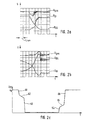
- the figure 2a time-dependent voltage curves the drain voltage of the output stage, the diode voltage on the freewheeling diode and the resulting total voltage during a switch-on process
- the figure 2b corresponding time-dependent voltage curves during switch-off processes
- FIG. 2c shows the time-dependent course the drain voltage with feedback according to the invention.
- An inductive consumer 10 is provided as the electrical load, for example an electric motor.
- This inductive Consumer 10 a free-wheeling diode 12 is connected in parallel.
- the inductive consumer 10 is via a power output stage 14 switched.
- To record the through the power stage 14 flowing current is one against ground interconnected measuring resistor 20 is provided, its potential tapped and fed to a PWM controller 18.
- This A setpoint is also supplied to PWM controller 18.
- the PWM controller 18 Out The setpoint and actual value, the PWM controller 18 generates a control signal 19, which a power stage control 16 as Input variable serves.
- the power stage control 16 comprises a push-pull stage 22 consisting of two transistors, their respective bases are electrically conductive with each other are connected.
- push-pull level 22 The basis of push-pull level 22 are both the control signal 19 via a series resistor and a feedback signal 21 supplied electrically conductive.
- the push-pull level 22 is determined by the positive supply voltage UB fed and on the other hand is connected to ground.
- the emitter of the one transistor of the push-pull stage 22 is over a series resistor with the gate connection of the power output stage 14 connected for forwarding a control signal 15.
- the two transistors of the push-pull stage 22 are as Emitter follower interconnected.
- the supply voltage UB which can be tapped off at the positive pole 56 arrives via a first choke 50 to the parallel connection of the inductive Consumer 10 and the freewheeling diode 12. Between the positive pole 56 and a negative pole 58 is a first capacitance 48 arranged. The minus potential is over a second Throttle 52 led to ground. Furthermore is a second Capacity 54 provided the positive supply potential of inductive consumer 10 couples to ground. First and second inductor 50, 52 and first and second capacitors 48, 54 are used for interference suppression.
- a feedback device 24 is from the positive supply potential controlled as an input variable.
- the positive Supply potential is based on a second Transistor 30 connected, the collector via a second Resistor 32 on the one hand with ground, on the other hand with the Base of a first transistor 26 is connected.
- the collector of the first transistor 26 is through a first resistor 28 switched to ground, the emitter of the first Transistor 26 is the output of a sixth Resistor 46 brought together in an electrically conductive manner and arrives thereafter as a feedback signal 21 to the base of the Push-pull stage 22.
- the feedback device 24 comprises an RC element 35, which consists of a fourth resistor 36 and a third capacitance 38 connected to ground and is fed by the positive supply potential becomes.
- the common potential of the fourth resistor 36 and the third capacitance 38 passes through a third resistor 34 to the emitter of the second transistor 30, on the other hand is the common potential with the base of one third transistor 44 and a fourth capacitance 40 with the collector of the third transistor 44 electrically conductive connected.
- the positive supply potential of the inductive Consumer 10 also passes through the fifth resistor 42 to the emitter of the third transistor 44.
- the Collector output of the third transistor 44 is the sixth resistor 46 with the output potential of the emitter of the first transistor 26 is connected in an electrically conductive manner, so that the feedback signal 21 arises.
- FIG. 1 Circuit The functionality and mode of operation of those shown in FIG. 1 Circuit is now closer with reference to Figures 2a to 2c described.
- the waveforms shown in Figures 2a and 2b show the drain voltage UDS, the diode voltage UDI and the resulting total voltage Uges when switching on ( Figure 2a) and when switching off ( Figure 2b) the power stage 14. If you look at the time-dependent Voltage curve of the total voltage Uges, so one can Detect voltage drop or a voltage peak. This Voltage dips or voltage increases depend on the Switching behavior of the freewheeling diode 12 together. The freewheeling diode 12 must first when switching (switching) occurs clear the junction capacitance to its switching state switch.
- a short circuit occurs for a short time, if the output stage 14 is already controlling the Free-wheeling diode 12, however, is not yet complete Lock mode is located. The result is a dip in voltage the total voltage Uges. This drop in voltage has an effect negative for conducted and radiated interference out. According to the invention, the detected voltage drop is now or voltage increase used to the control signal for the power stage 14 to influence specifically. This influence can be seen in Figure 2c.
- the Power stage 14 controlled with a lower slope, i.e. the switching process is deliberately slowed down. This slowdown in the switching behavior of the power output stage 14 is shown in the second area 62 and - for the Switching off the power stage 14 - as part of the fifth Area 65.
- the power stage control generates 16 a control signal 15 in such a way that the gate voltage UDS of power stage 14 with maximum slope (third area 63) changed until approximately that Ground potential is reached. The same thing happens for the switch-off phase of power stage 14, based on the fourth to sixth regions 64 to 66 are shown.
- the signal curve shown in FIG. 2c can be, for example achieve by the circuit shown in Figure 1.
- the voltage peaks Voltage drop during the switch-on phase, voltage increase during the switch-off phase
- the power stage control 16 in the form of the feedback signal 21. This will only occur in the times until the complete blocking operation or forward operation of the freewheeling diode 12 the switching behavior of the power output stage 14 slows down, causing the resulting EMC interference greatly decrease.
- the power stage control 16 is designed so that the maximum switching speed without feedback the power stage 14 is achieved what in the very steep flanks of the first, third, fourth and sixth areas 61, 63, 64, 66.
- the PWM controller 18 generates a control signal 19 in the Way that the power amplifier 14 are turned on should.
- the power output stage control 16 generates a control signal 15, which has a drain voltage UDS with maximum Switching speed (first area 61) causes. While feedback is not yet active during this period, there is still no feedback signal 21 by the Feedback device generated. Because so far it has exceeded Total voltage Uges not yet the one stored in the RC element 35 Reference voltage, so none of the three transistors 26, 30, 44 controlled.
- the power stage 14 is first with maximum Switching speed controlled. Because of the switching processes a voltage increase occurs in the freewheeling diode 12 the total voltage Uges according to Figure 2b. In the RC link 36 is the voltage level of the total voltage Uges before saved the voltage increase. Exceeds the voltage peak the reference voltage stored in the RC element by a certain amount, the third transistor 44 turned on. Now the positive voltage peak passes the third transistor 44 as a feedback signal 21 to the Basis of the push-pull stage 22. This becomes a control signal 15 generated in such a way that the switching speed reduced.
- the two chokes 50, 52 and the two capacitors 48, 54 are used to improve EMC behavior. Also ensure the two chokes 50, 52 that it is short term actually a detectable voltage drop or to a voltage increase in the total voltage Uges comes. This voltage dip or this voltage increase can be detected more easily and - according to the corresponding Signal adaptation via resistors 25, 32, 34, 42, 46 - also use accordingly as feedback signal 21.
- the circuit described in FIG. 1 can be used analogously can also be used if the power stage 14 at the positive pole and the inductive consumer 10 with free-wheeling diode 12 is connected to the negative pole. The levels are adjust accordingly.
- This circuit is particularly preferred for controlling an adjustment drive in a motor vehicle, for example for fan control or flap adjustment. However, it is not restricted to this.
Landscapes
- Engineering & Computer Science (AREA)
- Power Engineering (AREA)
- Dc-Dc Converters (AREA)
- Control Of Electric Motors In General (AREA)
Applications Claiming Priority (2)
| Application Number | Priority Date | Filing Date | Title |
|---|---|---|---|
| DE10133389A DE10133389A1 (de) | 2001-07-10 | 2001-07-10 | Vorrichtung zur Ansteuerung einer Leistungsendstufe |
| DE10133389 | 2001-07-10 |
Publications (2)
| Publication Number | Publication Date |
|---|---|
| EP1276216A2 true EP1276216A2 (fr) | 2003-01-15 |
| EP1276216A3 EP1276216A3 (fr) | 2006-07-26 |
Family
ID=7691215
Family Applications (1)
| Application Number | Title | Priority Date | Filing Date |
|---|---|---|---|
| EP02013212A Withdrawn EP1276216A3 (fr) | 2001-07-10 | 2002-06-15 | Dispositif d'agencement d'un étage de sortie de puissance |
Country Status (3)
| Country | Link |
|---|---|
| US (1) | US6873141B1 (fr) |
| EP (1) | EP1276216A3 (fr) |
| DE (1) | DE10133389A1 (fr) |
Families Citing this family (2)
| Publication number | Priority date | Publication date | Assignee | Title |
|---|---|---|---|---|
| US7276954B2 (en) * | 2002-06-26 | 2007-10-02 | Kabushiki Kaisha Toyota Jidoshokki | Driver for switching device |
| ITMI20081600A1 (it) * | 2008-09-09 | 2010-03-10 | Cross Technology S R L | Sistema attuatore-sensore |
Family Cites Families (6)
| Publication number | Priority date | Publication date | Assignee | Title |
|---|---|---|---|---|
| US4837495A (en) * | 1987-10-13 | 1989-06-06 | Astec U.S.A. (Hk) Limited | Current mode converter with controlled slope compensation |
| US4959606A (en) * | 1989-01-06 | 1990-09-25 | Uniphase Corporation | Current mode switching regulator with programmed offtime |
| US5197375A (en) * | 1991-08-30 | 1993-03-30 | The Middleby Corporation | Conveyor oven control |
| DE19736338A1 (de) * | 1997-08-21 | 1999-02-25 | Fahrzeugklimaregelung Gmbh | Leistungsendstufenschaltung mit PWM-Betrieb und Dauereinschaltbetrieb |
| DE19740697C1 (de) * | 1997-09-16 | 1999-02-11 | Siemens Ag | Verfahren und Vorrichtung zum Ansteuern einer integrierten Leistungsendstufe |
| US6342822B1 (en) * | 2000-11-28 | 2002-01-29 | Fairchild Semiconductor Corporation | Method and apparatus for implementing improved pulse width modulation |
-
2001
- 2001-07-10 DE DE10133389A patent/DE10133389A1/de not_active Ceased
-
2002
- 2002-06-15 EP EP02013212A patent/EP1276216A3/fr not_active Withdrawn
- 2002-07-08 US US10/190,781 patent/US6873141B1/en not_active Expired - Fee Related
Also Published As
| Publication number | Publication date |
|---|---|
| EP1276216A3 (fr) | 2006-07-26 |
| US6873141B1 (en) | 2005-03-29 |
| DE10133389A1 (de) | 2003-01-23 |
Similar Documents
| Publication | Publication Date | Title |
|---|---|---|
| DE10061563B4 (de) | Verfahren und Vorrichtung zum Ein- und Ausschalten von Leistungshalbleitern, insbesondere für ein drehzahlvariables Betreiben einer Asynchronmaschine, ein Betreiben einer Zündschaltung für Ottomotoren, sowie Schaltnetzteil | |
| DE69728715T2 (de) | Treiberschaltung | |
| EP1602169A2 (fr) | Circuit d'excitation pour alimentation a decoupage | |
| DE102004018823B3 (de) | Schaltungsanordnung mit einem Leistungstransistor und einer Ansteuerschaltung für den Leistungstransistor | |
| DE102012015787B3 (de) | Gepulster Gate-Treiber | |
| DE102009046255B4 (de) | Ansteuerverfahren für einen Halbleiterschalter und Schaltungsanordnung zum Ansteuern eines Gates eines Schalttransistors | |
| EP1715582B1 (fr) | Agencement de circuit destiné à piloter un commutateur de puissance électrique à haute tension | |
| WO2006125697A1 (fr) | Procede pour commander un moteur electrique alimente a partir d'un reseau de tension continue | |
| DE102004016927A1 (de) | Verfahren zur Strom- und Spannungsregelung für ein Schaltnetzteil | |
| DE10252827B3 (de) | Schaltungsanordnung zur schnellen Ansteuerung insbesondere induktiver Lasten | |
| EP2193534A1 (fr) | Dispositif et procédé d'alimentation électrique d'un commutateur à déclenchement de tension ou d'intensité | |
| DE10312221A1 (de) | Spannungsregler mit einstellbarer Ausgangsimpedanz | |
| EP1728324B1 (fr) | Circuit de commande destine a la commande d'un circuit electronique de puissance et procede correspondant | |
| EP1658676B1 (fr) | Circuit et procede pour transformer une tension d'alimentation a pics de tension | |
| EP3605832B1 (fr) | Courant de maintien adaptatif pour moteurs électriques à commutation électrique | |
| EP1737113A2 (fr) | Circuit de commande pour la régulation de courant et de tension d'un circuit d'alimentation à découpage | |
| EP2732541B1 (fr) | Système comprenant un dispositif d'alimentation en courant à isolation galvanique | |
| EP1276216A2 (fr) | Dispositif d'agencement d'un étage de sortie de puissance | |
| EP1880096B1 (fr) | Procede et dispositif de commande electrique d'une soupape au moyen d'un element de fermeture mecanique | |
| EP1703629B1 (fr) | Procédé pour la commande digitale de courant | |
| DE10345235B4 (de) | Stromversorgungsschaltung und Verfahren zur Stromversorgung einer Last | |
| EP1701434A2 (fr) | Circuit de commande pour le commutateur d'une alimentation de puissance à découpage | |
| DE4330996A1 (de) | Steuereinrichtung für einen elektrischen, insbesondere einen induktiven Verbraucher | |
| DE19718814C2 (de) | Verfahren und Vorrichtung zur Leistungsssteuerung von an ein Wechselspannungs-Versorgungsnetz angeschlossenen elektrischen Verbrauchern | |
| DE102009041451B4 (de) | Ansteuereinheit für elektrische und/oder pneumatische Verstellantriebe |
Legal Events
| Date | Code | Title | Description |
|---|---|---|---|
| PUAI | Public reference made under article 153(3) epc to a published international application that has entered the european phase |
Free format text: ORIGINAL CODE: 0009012 |
|
| AK | Designated contracting states |
Kind code of ref document: A2 Designated state(s): AT BE CH CY DE DK ES FI FR GB GR IE IT LI LU MC NL PT SE TR |
|
| AX | Request for extension of the european patent |
Free format text: AL;LT;LV;MK;RO;SI |
|
| PUAL | Search report despatched |
Free format text: ORIGINAL CODE: 0009013 |
|
| AK | Designated contracting states |
Kind code of ref document: A3 Designated state(s): AT BE CH CY DE DK ES FI FR GB GR IE IT LI LU MC NL PT SE TR |
|
| AX | Request for extension of the european patent |
Extension state: AL LT LV MK RO SI |
|
| RIC1 | Information provided on ipc code assigned before grant |
Ipc: H02M 3/156 20060101AFI20060616BHEP |
|
| 17P | Request for examination filed |
Effective date: 20070126 |
|
| 17Q | First examination report despatched |
Effective date: 20070226 |
|
| AKX | Designation fees paid |
Designated state(s): DE ES FR GB IT |
|
| STAA | Information on the status of an ep patent application or granted ep patent |
Free format text: STATUS: THE APPLICATION IS DEEMED TO BE WITHDRAWN |
|
| 18D | Application deemed to be withdrawn |
Effective date: 20160105 |