EP1275963A2 - Dispositif permettant d'effectuer des tests sur un volumètre - Google Patents
Dispositif permettant d'effectuer des tests sur un volumètre Download PDFInfo
- Publication number
- EP1275963A2 EP1275963A2 EP02013986A EP02013986A EP1275963A2 EP 1275963 A2 EP1275963 A2 EP 1275963A2 EP 02013986 A EP02013986 A EP 02013986A EP 02013986 A EP02013986 A EP 02013986A EP 1275963 A2 EP1275963 A2 EP 1275963A2
- Authority
- EP
- European Patent Office
- Prior art keywords
- area
- fluid
- pickup
- volume
- pickup area
- Prior art date
- Legal status (The legal status is an assumption and is not a legal conclusion. Google has not performed a legal analysis and makes no representation as to the accuracy of the status listed.)
- Granted
Links
Images


Classifications
-
- G—PHYSICS
- G01—MEASURING; TESTING
- G01N—INVESTIGATING OR ANALYSING MATERIALS BY DETERMINING THEIR CHEMICAL OR PHYSICAL PROPERTIES
- G01N27/00—Investigating or analysing materials by the use of electric, electrochemical, or magnetic means
- G01N27/26—Investigating or analysing materials by the use of electric, electrochemical, or magnetic means by investigating electrochemical variables; by using electrolysis or electrophoresis
- G01N27/28—Electrolytic cell components
- G01N27/30—Electrodes, e.g. test electrodes; Half-cells
- G01N27/327—Biochemical electrodes, e.g. electrical or mechanical details for in vitro measurements
- G01N27/3271—Amperometric enzyme electrodes for analytes in body fluids, e.g. glucose in blood
- G01N27/3272—Test elements therefor, i.e. disposable laminated substrates with electrodes, reagent and channels
-
- B—PERFORMING OPERATIONS; TRANSPORTING
- B01—PHYSICAL OR CHEMICAL PROCESSES OR APPARATUS IN GENERAL
- B01L—CHEMICAL OR PHYSICAL LABORATORY APPARATUS FOR GENERAL USE
- B01L3/00—Containers or dishes for laboratory use, e.g. laboratory glassware; Droppers
- B01L3/50—Containers for the purpose of retaining a material to be analysed, e.g. test tubes
- B01L3/502—Containers for the purpose of retaining a material to be analysed, e.g. test tubes with fluid transport, e.g. in multi-compartment structures
- B01L3/5027—Containers for the purpose of retaining a material to be analysed, e.g. test tubes with fluid transport, e.g. in multi-compartment structures by integrated microfluidic structures, i.e. dimensions of channels and chambers are such that surface tension forces are important, e.g. lab-on-a-chip
-
- B—PERFORMING OPERATIONS; TRANSPORTING
- B01—PHYSICAL OR CHEMICAL PROCESSES OR APPARATUS IN GENERAL
- B01L—CHEMICAL OR PHYSICAL LABORATORY APPARATUS FOR GENERAL USE
- B01L2200/00—Solutions for specific problems relating to chemical or physical laboratory apparatus
- B01L2200/02—Adapting objects or devices to another
- B01L2200/026—Fluid interfacing between devices or objects, e.g. connectors, inlet details
-
- B—PERFORMING OPERATIONS; TRANSPORTING
- B01—PHYSICAL OR CHEMICAL PROCESSES OR APPARATUS IN GENERAL
- B01L—CHEMICAL OR PHYSICAL LABORATORY APPARATUS FOR GENERAL USE
- B01L2300/00—Additional constructional details
- B01L2300/06—Auxiliary integrated devices, integrated components
- B01L2300/0627—Sensor or part of a sensor is integrated
- B01L2300/0663—Whole sensors
-
- B—PERFORMING OPERATIONS; TRANSPORTING
- B01—PHYSICAL OR CHEMICAL PROCESSES OR APPARATUS IN GENERAL
- B01L—CHEMICAL OR PHYSICAL LABORATORY APPARATUS FOR GENERAL USE
- B01L2300/00—Additional constructional details
- B01L2300/06—Auxiliary integrated devices, integrated components
- B01L2300/0681—Filter
-
- B—PERFORMING OPERATIONS; TRANSPORTING
- B01—PHYSICAL OR CHEMICAL PROCESSES OR APPARATUS IN GENERAL
- B01L—CHEMICAL OR PHYSICAL LABORATORY APPARATUS FOR GENERAL USE
- B01L2300/00—Additional constructional details
- B01L2300/06—Auxiliary integrated devices, integrated components
- B01L2300/069—Absorbents; Gels to retain a fluid
-
- B—PERFORMING OPERATIONS; TRANSPORTING
- B01—PHYSICAL OR CHEMICAL PROCESSES OR APPARATUS IN GENERAL
- B01L—CHEMICAL OR PHYSICAL LABORATORY APPARATUS FOR GENERAL USE
- B01L2300/00—Additional constructional details
- B01L2300/08—Geometry, shape and general structure
- B01L2300/0809—Geometry, shape and general structure rectangular shaped
- B01L2300/0825—Test strips
-
- B—PERFORMING OPERATIONS; TRANSPORTING
- B01—PHYSICAL OR CHEMICAL PROCESSES OR APPARATUS IN GENERAL
- B01L—CHEMICAL OR PHYSICAL LABORATORY APPARATUS FOR GENERAL USE
- B01L2400/00—Moving or stopping fluids
- B01L2400/04—Moving fluids with specific forces or mechanical means
- B01L2400/0403—Moving fluids with specific forces or mechanical means specific forces
- B01L2400/0406—Moving fluids with specific forces or mechanical means specific forces capillary forces
Definitions
- the present invention relates generally to blood monitoring devices and, more particularly, to a volume metering test device for obtaining a sample of blood.
- One example of a need for quickly obtaining a sample of blood is in connection with a blood glucose monitoring system where a user must frequently use the system to monitor the user's blood glucose level.
- Those who have irregular blood glucose concentration levels are medically required to self-monitor their blood glucose concentration level.
- An irregular blood glucose level can be brought on by a variety of reasons including illness, such as diabetes.
- the purpose of monitoring the blood glucose concentration level is to determine the blood glucose concentration level and then to take corrective action, based upon whether the level is too high or too low, to bring the level back within a normal range.
- the failure to take corrective action can have serious implications.
- hypoglycemia a condition known as hypoglycemia
- a person can become nervous, shaky, and confused. That person's judgment may become impaired and that person may eventually pass out.
- a person can also become very ill if their blood glucose level becomes too high, a condition known as hyperglycemia. Both conditions, hypoglycemia and hyperglycemia, are potentially life-threatening emergencies.
- a prior art blood glucose testing device 100 is illustrated in FIG. 1.
- the portable nature of these devices 100 enables the users to conveniently test their blood glucose levels wherever the user may be.
- the glucose testing device contains a test sensor 102 to harvest the blood for analysis.
- the device 100 contains a switch 104 to activate the device 100 and a display 106 to display the blood glucose analysis results.
- a drop of blood is obtained from the fingertip using a lancing device.
- a prior art lancing device 120 is illustrated in FIG. 2.
- the lancing device 120 contains a needle lance 122 to puncture the skin. Some lancing devices implement a vacuum to facilitate drawing blood.
- the blood is harvested using the test sensor 102.
- the test sensor 102 which is inserted into a testing unit 100, is brought into contact with the blood drop.
- the test sensor 102 draws the blood to the inside of the test unit 100, which then determines the concentration of glucose in the blood.
- the results of the test are displayed on the display 106 of the test unit 100, the test sensor 102 is discarded. Each new test requires a new test sensor 102.
- test sensor used needs a minimum amount of blood to provide accurate results. If the proper amount of blood is not received, inaccurate results may be generated.
- Another problem associated with some conventional test sensors is that the user cannot ensure that the proper amount of blood has been obtained.
- the user applies the blood directly onto a read area and then obtains a reading from the device. If an unusual reading is given, the user may surmise that the unusual reading was caused by an improper amount of blood being obtained. The user may then try again. There is no way for the user to know, however, if that is the true reason for the unusual result.
- Air gaps in the blood sample can also cause inaccurate readings, requiring the user to retest.
- Another problem associated with some conventional test sensors is that the user's blood physically contacts the elements within the testing unit. Cross-contamination can be a problem if the monitoring device is used by more than one user, such as in a doctor's office or other clinical setting.
- a test sensor adapted to test a concentration of an analyte in a fluid has a pickup area having a first volume for receiving the fluid.
- a read area In fluid communication with the pickup area is a read area having a second volume, which is less than the first volume. Since the second volume is less than the first volume, fluid from the pickup area will flow into the read area only after the pickup area is full.
- the read area also contains a reagent that is adapted to indicate the concentration of the analyte in the fluid.
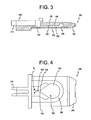
- FIG. 3 depicts a schematic view of the side of a test device 200 according to one embodiment of the present invention.
- the test device 200 includes a format 205, a pickup area 210, a transfer area 220, a read area 230, a vent area 240, and a cover 250.
- the test device 200 is designed to collect a fluid, for example, blood, so the fluid may be tested for the concentration of a particular analyte, such as glucose.
- a fluid for example, blood
- analyte such as glucose
- the fluid described will be blood pricked from a finger and the analyte will be glucose. It is understood that the embodiment may also be used for other fluids and analytes and that these only serve as examples.
- the pickup area 210 is placed in contact with the wound. Using capillary action, described below, the blood moves into the pickup area 210. The blood flows from the pickup area into the transfer area 220 and then into the read area 230. The cover 250 develops the capillary gap in the read area 230 and also retains the blood within the test device, protecting the test unit from contamination.
- the read area 230 includes a reagent which is designed to react with the glucose to produce a colormetric or electrochemical response.
- the test unit 100 then measures the colormetric or electrochemical response.
- the reagent used in the read area 230 depends on the type of analyte desired.
- the test device 200 can be used in conjunction with a photometric test unit, which measures the colormetric reaction.
- a photometric test unit which measures the colormetric reaction.
- the reagent used causes a change in color in the read area.
- the photometric test unit then reads the amount of color change.
- Photometric testing is described in more detail in commonly-owned U.S. Patent No. 5,611,999 entitled “Diffuse Reflectance Readhead” which is incorporated herein by reference in its entirety. It is also contemplated that other methods of testing the concentration of glucose in blood may be utilized.
- an electrochemical test unit is employed.
- the read area 230 includes a pair of electrodes (not shown).
- electrochemical analysis the change in current across the electrodes caused by the reaction of the glucose and the reagent creates an oxidation current at the electrodes which is directly proportional to the user's blood glucose concentration.
- the current can be measured by an electrochemical test unit coupled to a pair of terminals (not shown) corresponding to the electrodes.
- the electrochemical test unit can then communicate to the user the blood glucose concentration.
- An example of an electrochemical test system is described in detail by commonly-owned U.S. Patent No. 5,723,284 entitled "Control Solution And Method For Testing The Performance Of An Electrochemical Device For Determining The Concentration Of An Analyte In Blood” which is incorporated herein by reference in its entirety.
- FIGS. 3 through 5 a side view, a bottom view, and a top view are shown.
- the pickup area 210 has a first sidewall 260 and a second sidewall 270, which create a capillary gap 280 having a thickness t 1 .
- the capillary gap 280 thus, facilitates the capillary action.
- Proceeding the pickup area 210 is a nib 215.
- the nib 215 does not have either a floor or a ceiling. Elimination of a floor and a ceiling at the pickup area 210 insures that the pickup area 210 is not closed when the nib 215 is in direct contact with the wound on the finger.
- the pickup area 210 has a volume v 1 , which is larger than the required volume needed to accurately test the blood.
- the volume v 1 of the pickup area 210 is designed to ensure that at least a requisite amount of blood is obtained with each test. Creating a large pickup area 210 decreases the likelihood that a user will need to retest due to lack of a sufficient volume of blood.
- the transfer area 220 is in fluid communication with the pickup area 210 and the read area 230.
- the transfer area 220 is designed to transfer the blood from the pickup area 210 to the read area 230.
- a second capillary gap 290 having a thickness of t 2 is created in the transfer area by a first and second sidewall 300, 310.
- the thickness t 2 of the second capillary gap 290 is less than the thickness of t 1 of the first capillary gap 280.
- the blood will not flow into an area with a smaller capillary gap until the area with the larger capillary gap is completely filled. In other words, an area with a smaller capillary gap cannot exert enough force to draw blood from an area having a larger capillary gap.
- the transfer area 220 has a volume v 2 which is less than the volume v 1 of the pickup area 210. Since the volume v 1 of the pickup area 210 is larger than the volume v 2 of the transfer area and the pickup area 210 must be filled prior to the transfer area 220 drawing the blood, the testing device 200 ensures that at least a requisite amount of blood is obtained from the user.
- the read area 230 is an island surrounded by the vent area 240. As blood moves into the read area 230, the air in the read area 230 escapes into the vent area 240. This ensures that the blood continues to flow into the read area 230 and also aids in the prevention of air pockets forming in the read area 230 during the testing process.
- the read area 230 comprises a floor 320 and a ceiling 330.
- the floor 320 is a top side of the cover 250.
- the ceiling 330 is a portion of the format, illustrated in FIG. 3.
- the read area 230 does not include any sidewalls. The inventor has found that air can become trapped along the sidewalls of the read area 230. The presence of air in the read area 230 increases the risk of obtaining an inaccurate result. By eliminating the sidewalls, air cannot become entrapped in the read area 230, as it all flows out into the vent area 240, and the possibility of erroneous test results is decreased.
- the floor 320 and ceiling 330 create a capillary gap 340 having a thickness t 3 (FIG. 6) that is less than the thickness t 2 of the capillary gap 290 of the transfer area 220. Therefore, blood will not move into the read area 230 until the transfer area 220 is completely filled.
- the read area 230 has a volume v 3 which is less than the volume v 2 of the transfer area. Thus, once the transfer area 220 is completely filled, there is enough blood drawn into the testing device 200 to insure a proper reading. Since the read area 230 will not begin to draw the blood from the transfer area 220 until the transfer area 220 is full, a user may be assured that enough blood to provide an accurate reading has been obtained.
- the capillary gap 340 is maintained at a thickness t 3 because the format 205 (the ceiling 330) is made of a plastic film that retains its shape.
- the volume v 3 of the read area is from about 70 to about 80 percent of the volume v 1 of the pickup area.
- the pickup area 210 has a volume of from about 5.0 to about 5.5 microliters and the read area 230 has a volume from about 3.5 to about 4.0 microliters.
- the volume v 2 of the transfer area 220 may be anywhere between the volume v 1 of the pickup area 210 and the volume v 3 of the read area 230.
- the thickness t 1 of the first capillary gap 280 is in the range of about 0.025 to about 0.030 inch.
- the thickness t 2 of the second capillary gap 290 is in the range of about 0.015 to about 0.020 inch.
- the thickness t 2 of the second capillary gap 290 is less than the thickness t 1 of the first capillary gap 280.
- the thickness t 3 of the third capillary gap 340 is in the range of about 0.008 to about 0.0012 inch.
- the thickness t 3 of the third capillary gap 340 must remain less than the thicknesses t 1 and t 2 of the first and second capillary gaps 280, 290.
- the operation of the device will now be described.
- the user moves the pickup area 210 into contact with a drop of blood on the user's fingertip.
- the pickup area 210 then fills with blood from the user's fingertip.
- the transfer area 220 begins to fill with the blood.
- the user may then remove the testing device 200 from the user's fingertip. Since the transfer area 220 does not begin to fill with blood until after the pickup area is filled, and the pickup area has a volume v 1 greater than the requisite volume needed for an accurate reading, the user can be assured that enough blood has been drawn.
- the blood then begins to fill the read area 230.
- the sensor then reads the resulting change and indicates the glucose concentration to the user.
- FIG. 7 is a top view of the test device
- FIG. 8 is a perspective view of the test device of FIG. 7, cut along line 7-7.
- the read area 230 includes a capillary gap 820 created by supports 830, a filter 810, and a reagent impregnated paper 840.
- the filter 830 and reagent impregnated paper 840 are below the capillary gap 820. In this configuration, the blood needs to pass through the filter 810 before the reagent reacts with the blood.
- the capillary gap 820 above the filter 810 is produced by supports in the test device 200 and is arranged in such a pattern to promote spreading across the top surface of the filter 810.
- a uniform color change can be created along the read surface of the reagent impregnated paper 840, allowing for an accurate reading by a photometric test unit.
- the capillary gap distance t 4 is less than the thickness t 2 of the capillary gap 290 of the transfer area 220.
- the flow of blood acts the same in this embodiment.
Landscapes
- Chemical & Material Sciences (AREA)
- Health & Medical Sciences (AREA)
- Life Sciences & Earth Sciences (AREA)
- Chemical Kinetics & Catalysis (AREA)
- Analytical Chemistry (AREA)
- General Health & Medical Sciences (AREA)
- Hematology (AREA)
- Physics & Mathematics (AREA)
- Pathology (AREA)
- Biophysics (AREA)
- Molecular Biology (AREA)
- Electrochemistry (AREA)
- Dispersion Chemistry (AREA)
- Biochemistry (AREA)
- General Physics & Mathematics (AREA)
- Immunology (AREA)
- Clinical Laboratory Science (AREA)
- Investigating Or Analysing Biological Materials (AREA)
- Measurement Of The Respiration, Hearing Ability, Form, And Blood Characteristics Of Living Organisms (AREA)
- Investigating Or Analysing Materials By The Use Of Chemical Reactions (AREA)
- Automatic Analysis And Handling Materials Therefor (AREA)
- Investigation Of Foundation Soil And Reinforcement Of Foundation Soil By Compacting Or Drainage (AREA)
- Diaphragms For Electromechanical Transducers (AREA)
- Analysing Materials By The Use Of Radiation (AREA)
Applications Claiming Priority (2)
| Application Number | Priority Date | Filing Date | Title |
|---|---|---|---|
| US30355001P | 2001-07-09 | 2001-07-09 | |
| US303550P | 2001-07-09 |
Publications (3)
| Publication Number | Publication Date |
|---|---|
| EP1275963A2 true EP1275963A2 (fr) | 2003-01-15 |
| EP1275963A3 EP1275963A3 (fr) | 2004-11-17 |
| EP1275963B1 EP1275963B1 (fr) | 2009-08-12 |
Family
ID=23172619
Family Applications (1)
| Application Number | Title | Priority Date | Filing Date |
|---|---|---|---|
| EP02013986A Expired - Lifetime EP1275963B1 (fr) | 2001-07-09 | 2002-06-26 | Dispositif permettant d'effectuer des tests sur un volumètre |
Country Status (9)
| Country | Link |
|---|---|
| US (1) | US7776608B2 (fr) |
| EP (1) | EP1275963B1 (fr) |
| JP (1) | JP3863075B2 (fr) |
| AT (1) | ATE439586T1 (fr) |
| AU (1) | AU785113B2 (fr) |
| CA (1) | CA2392154A1 (fr) |
| DE (1) | DE60233296D1 (fr) |
| DK (1) | DK1275963T3 (fr) |
| ES (1) | ES2329765T3 (fr) |
Families Citing this family (13)
| Publication number | Priority date | Publication date | Assignee | Title |
|---|---|---|---|---|
| US7776608B2 (en) | 2001-07-09 | 2010-08-17 | Bayer Healthcare Llc | Volume meter testing device and method of use |
| US7604775B2 (en) * | 2002-08-12 | 2009-10-20 | Bayer Healthcare Llc | Fluid collecting and monitoring device |
| US8153081B2 (en) * | 2003-05-29 | 2012-04-10 | Bayer Healthcare Llc | Test sensor and method for manufacturing the same |
| JP2009536733A (ja) * | 2006-05-08 | 2009-10-15 | バイエル・ヘルスケア・エルエルシー | 充填不足の予防機能を備える試験センサ |
| DE102006025477B4 (de) * | 2006-05-30 | 2009-01-15 | Ekf - Diagnostic Gmbh | Küvette und Verfahren zu ihrer Herstellung |
| DE102006038271A1 (de) * | 2006-08-11 | 2008-02-14 | Senslab-Gesellschaft Zur Entwicklung Und Herstellung Bioelektrochemischer Sensoren Mbh | Sensorvorrichtung mit strukturierter Durchflusszelle |
| JP4811267B2 (ja) * | 2006-12-22 | 2011-11-09 | パナソニック株式会社 | マイクロチップ及びそれを用いた分析デバイス |
| GB0918462D0 (en) * | 2009-10-21 | 2009-12-09 | Spd Swiss Prec Diagnostics Gmb | Connection assembly and method |
| US9289763B2 (en) * | 2012-07-23 | 2016-03-22 | Tasso, Inc. | Methods, systems, and devices relating to open microfluidic channels |
| US20140116893A1 (en) * | 2012-10-29 | 2014-05-01 | Lifescan, Inc. | System and method for reduction of perceived inaccuracy of analyte measurements |
| EP2778679B1 (fr) * | 2013-03-15 | 2017-09-27 | Ortho-Clinical Diagnostics, Inc. | Dispositif de collecte d'échantillon de fluide en forme de disque rotatif |
| CN107238573A (zh) * | 2016-03-29 | 2017-10-10 | 光宝电子(广州)有限公司 | 流体检测装置 |
| AU2019384106A1 (en) | 2018-11-20 | 2021-04-29 | Xatek, Inc. | Dielectric spectroscopy sensing apparaus and method of use |
Citations (5)
| Publication number | Priority date | Publication date | Assignee | Title |
|---|---|---|---|---|
| EP0269240A1 (fr) * | 1986-10-29 | 1988-06-01 | Biotrack, Inc. | Séparateur de sang dans des conditions de basse pression |
| EP0443231A1 (fr) * | 1990-02-22 | 1991-08-28 | Editek, Inc. | Dispositif multicouche pour tests de diagnostic en vue de la détermination de substances dans des liquides |
| EP0483117A2 (fr) * | 1985-08-05 | 1992-04-29 | Boehringer Mannheim Corporation | Dispositif d'écoulement capillaire |
| US5700695A (en) * | 1994-06-30 | 1997-12-23 | Zia Yassinzadeh | Sample collection and manipulation method |
| EP0974840A2 (fr) * | 1998-07-20 | 2000-01-26 | Lifescan, Inc. | Elément fluidique pour la diagnose médicale |
Family Cites Families (48)
| Publication number | Priority date | Publication date | Assignee | Title |
|---|---|---|---|---|
| SE399768B (sv) * | 1975-09-29 | 1978-02-27 | Lilja Jan E | Kyvett for provtagning, blandning av, provet med ett reagensmedel och direkt utforande av, serskilt optisk, analys av det med reagensmedlet blandade provet |
| US4426451A (en) * | 1981-01-28 | 1984-01-17 | Eastman Kodak Company | Multi-zoned reaction vessel having pressure-actuatable control means between zones |
| US5004923A (en) * | 1985-08-05 | 1991-04-02 | Biotrack, Inc. | Capillary flow device |
| US4761381A (en) * | 1985-09-18 | 1988-08-02 | Miles Inc. | Volume metering capillary gap device for applying a liquid sample onto a reactive surface |
| US4935346A (en) * | 1986-08-13 | 1990-06-19 | Lifescan, Inc. | Minimum procedure system for the determination of analytes |
| US5049487A (en) * | 1986-08-13 | 1991-09-17 | Lifescan, Inc. | Automated initiation of timing of reflectance readings |
| DE3630999A1 (de) * | 1986-09-12 | 1988-03-17 | Boehringer Mannheim Gmbh | Mehrschichtiger testtraeger |
| US4895798A (en) * | 1987-11-13 | 1990-01-23 | Miles, Inc. | Test devices for determination of occult blood |
| US5039617A (en) * | 1989-04-20 | 1991-08-13 | Biotrack, Inc. | Capillary flow device and method for measuring activated partial thromboplastin time |
| US5472671A (en) * | 1989-04-26 | 1995-12-05 | Nilsson; Sven-Erik | Cuvette |
| US5286454A (en) * | 1989-04-26 | 1994-02-15 | Nilsson Sven Erik | Cuvette |
| US6395227B1 (en) * | 1989-08-28 | 2002-05-28 | Lifescan, Inc. | Test strip for measuring analyte concentration over a broad range of sample volume |
| US6156270A (en) * | 1992-05-21 | 2000-12-05 | Biosite Diagnostics, Inc. | Diagnostic devices and apparatus for the controlled movement of reagents without membranes |
| US5843691A (en) * | 1993-05-15 | 1998-12-01 | Lifescan, Inc. | Visually-readable reagent test strip |
| DE4326339A1 (de) * | 1993-08-05 | 1995-02-09 | Boehringer Mannheim Gmbh | System zur Analyse von Probenflüssigkeiten |
| US5770389A (en) * | 1993-09-27 | 1998-06-23 | Abbott Laboratories | Apparatus and method for determining the quanity of an analyte in a biological sample by means of transmission photometry |
| US5585069A (en) * | 1994-11-10 | 1996-12-17 | David Sarnoff Research Center, Inc. | Partitioned microelectronic and fluidic device array for clinical diagnostics and chemical synthesis |
| JPH08145980A (ja) | 1994-11-25 | 1996-06-07 | Otax Kk | 水性液体検査用チップ |
| DE19523049A1 (de) * | 1995-06-24 | 1997-01-02 | Boehringer Mannheim Gmbh | Mehrschichtiges Analysenelement zur Bestimmung eines Analyten in einer Flüssigkeit |
| US5611999A (en) * | 1995-09-05 | 1997-03-18 | Bayer Corporation | Diffused light reflectance readhead |
| US6299838B1 (en) * | 1995-10-06 | 2001-10-09 | Kyoto Daiichi Kagaku Co., Ltd. | Test apparatus for assaying a component in a liquid sample |
| JPH09133673A (ja) | 1995-11-10 | 1997-05-20 | Kdk Corp | 液体試料測定用具及び液体試料測定方法 |
| US5723284A (en) * | 1996-04-01 | 1998-03-03 | Bayer Corporation | Control solution and method for testing the performance of an electrochemical device for determining the concentration of an analyte in blood |
| US5962215A (en) * | 1996-04-05 | 1999-10-05 | Mercury Diagnostics, Inc. | Methods for testing the concentration of an analyte in a body fluid |
| DE19629656A1 (de) * | 1996-07-23 | 1998-01-29 | Boehringer Mannheim Gmbh | Diagnostischer Testträger mit mehrschichtigem Testfeld und Verfahren zur Bestimmung von Analyt mit dessen Hilfe |
| US6027459A (en) * | 1996-12-06 | 2000-02-22 | Abbott Laboratories | Method and apparatus for obtaining blood for diagnostic tests |
| US5759364A (en) * | 1997-05-02 | 1998-06-02 | Bayer Corporation | Electrochemical biosensor |
| US6300138B1 (en) * | 1997-08-01 | 2001-10-09 | Qualigen, Inc. | Methods for conducting tests |
| DE19753847A1 (de) * | 1997-12-04 | 1999-06-10 | Roche Diagnostics Gmbh | Analytisches Testelement mit Kapillarkanal |
| DE19815684A1 (de) * | 1998-04-08 | 1999-10-14 | Roche Diagnostics Gmbh | Verfahren zur Herstellung von analytischen Hilfsmitteln |
| US6162397A (en) * | 1998-08-13 | 2000-12-19 | Lifescan, Inc. | Visual blood glucose test strip |
| US6338790B1 (en) * | 1998-10-08 | 2002-01-15 | Therasense, Inc. | Small volume in vitro analyte sensor with diffusible or non-leachable redox mediator |
| US6368563B1 (en) * | 1999-03-12 | 2002-04-09 | Integ, Inc. | Collection well for body fluid tester |
| ATE316651T1 (de) * | 1999-11-15 | 2006-02-15 | Arkray Inc | Biosensor |
| US6403037B1 (en) * | 2000-02-04 | 2002-06-11 | Cepheid | Reaction vessel and temperature control system |
| DE10008906A1 (de) | 2000-02-25 | 2001-08-30 | Bayer Ag | Testsystem auf Basis von Mikrokapillaren |
| US6612111B1 (en) | 2000-03-27 | 2003-09-02 | Lifescan, Inc. | Method and device for sampling and analyzing interstitial fluid and whole blood samples |
| US6814843B1 (en) | 2000-11-01 | 2004-11-09 | Roche Diagnostics Corporation | Biosensor |
| US7776608B2 (en) | 2001-07-09 | 2010-08-17 | Bayer Healthcare Llc | Volume meter testing device and method of use |
| DE10140680A1 (de) * | 2001-08-24 | 2003-03-06 | Bayer Ag | Spektroskopisches Testsystem auf Basis von Mikrokapillaren |
| US6949297B2 (en) * | 2001-11-02 | 2005-09-27 | 3M Innovative Properties Company | Hybrid adhesives, articles, and methods |
| US6723500B2 (en) * | 2001-12-05 | 2004-04-20 | Lifescan, Inc. | Test strips having reaction zones and channels defined by a thermally transferred hydrophobic barrier |
| CA2419199A1 (fr) * | 2002-03-05 | 2003-09-05 | Bayer Healthcare, Llc | Format optique a invasion minimale avec aiguille integree |
| US20030143113A2 (en) * | 2002-05-09 | 2003-07-31 | Lifescan, Inc. | Physiological sample collection devices and methods of using the same |
| US7604775B2 (en) | 2002-08-12 | 2009-10-20 | Bayer Healthcare Llc | Fluid collecting and monitoring device |
| CN1917810A (zh) | 2004-02-06 | 2007-02-21 | 拜尔健康护理有限责任公司 | 用于对在体液内的分析物进行测量的方法和设备 |
| EP1746929A2 (fr) | 2004-05-14 | 2007-01-31 | Bayer HealthCare LLC | Bande de test diagnostique permettant de recueillir et de detecter un analyste dans un echantillon de fluide et procede d'utilisation de cette bande |
| CN101088003A (zh) | 2004-12-13 | 2007-12-12 | 拜尔保健有限公司 | 用于确定体液中被分析物的透射光谱学系统 |
-
2002
- 2002-06-20 US US10/174,833 patent/US7776608B2/en not_active Expired - Fee Related
- 2002-06-26 DK DK02013986T patent/DK1275963T3/da active
- 2002-06-26 EP EP02013986A patent/EP1275963B1/fr not_active Expired - Lifetime
- 2002-06-26 DE DE60233296T patent/DE60233296D1/de not_active Expired - Lifetime
- 2002-06-26 AT AT02013986T patent/ATE439586T1/de not_active IP Right Cessation
- 2002-06-26 ES ES02013986T patent/ES2329765T3/es not_active Expired - Lifetime
- 2002-06-28 CA CA002392154A patent/CA2392154A1/fr not_active Abandoned
- 2002-07-01 AU AU52747/02A patent/AU785113B2/en not_active Ceased
- 2002-07-05 JP JP2002197563A patent/JP3863075B2/ja not_active Expired - Fee Related
Patent Citations (5)
| Publication number | Priority date | Publication date | Assignee | Title |
|---|---|---|---|---|
| EP0483117A2 (fr) * | 1985-08-05 | 1992-04-29 | Boehringer Mannheim Corporation | Dispositif d'écoulement capillaire |
| EP0269240A1 (fr) * | 1986-10-29 | 1988-06-01 | Biotrack, Inc. | Séparateur de sang dans des conditions de basse pression |
| EP0443231A1 (fr) * | 1990-02-22 | 1991-08-28 | Editek, Inc. | Dispositif multicouche pour tests de diagnostic en vue de la détermination de substances dans des liquides |
| US5700695A (en) * | 1994-06-30 | 1997-12-23 | Zia Yassinzadeh | Sample collection and manipulation method |
| EP0974840A2 (fr) * | 1998-07-20 | 2000-01-26 | Lifescan, Inc. | Elément fluidique pour la diagnose médicale |
Also Published As
| Publication number | Publication date |
|---|---|
| DK1275963T3 (da) | 2009-11-16 |
| US20030007893A1 (en) | 2003-01-09 |
| US7776608B2 (en) | 2010-08-17 |
| JP2003107098A (ja) | 2003-04-09 |
| ATE439586T1 (de) | 2009-08-15 |
| EP1275963B1 (fr) | 2009-08-12 |
| CA2392154A1 (fr) | 2003-01-09 |
| JP3863075B2 (ja) | 2006-12-27 |
| AU785113B2 (en) | 2006-09-21 |
| AU5274702A (en) | 2003-01-16 |
| EP1275963A3 (fr) | 2004-11-17 |
| ES2329765T3 (es) | 2009-12-01 |
| DE60233296D1 (de) | 2009-09-24 |
Similar Documents
| Publication | Publication Date | Title |
|---|---|---|
| US6960287B2 (en) | Underfill detection system for a test sensor | |
| AU770595B2 (en) | Hollow microneedle patch | |
| EP1346686B1 (fr) | Dispositif de collection de fluides avec lancette et domaine de réaction intégrée | |
| AU2003204930B2 (en) | Sensor with Integrated Lancet | |
| EP1174083A2 (fr) | Lance mince pour capteur de test | |
| US20040248312A1 (en) | Sensor with integrated lancet | |
| US7776608B2 (en) | Volume meter testing device and method of use | |
| JP2010525371A (ja) | 較正のないアナライトセンサおよび方法 | |
| US9448197B2 (en) | Marker for readings taken from alternative site tests | |
| EP3665479B1 (fr) | Dispositif pour détection précise de substance physiologique dans le sang | |
| JP2005526953A (ja) | エンボス加工されたテストストリップシステム |
Legal Events
| Date | Code | Title | Description |
|---|---|---|---|
| PUAI | Public reference made under article 153(3) epc to a published international application that has entered the european phase |
Free format text: ORIGINAL CODE: 0009012 |
|
| AK | Designated contracting states |
Kind code of ref document: A2 Designated state(s): AT BE CH CY DE DK ES FI FR GB GR IE IT LI LU MC NL PT SE TR |
|
| AX | Request for extension of the european patent |
Free format text: AL;LT;LV;MK;RO;SI |
|
| PUAL | Search report despatched |
Free format text: ORIGINAL CODE: 0009013 |
|
| AK | Designated contracting states |
Kind code of ref document: A3 Designated state(s): AT BE CH CY DE DK ES FI FR GB GR IE IT LI LU MC NL PT SE TR |
|
| AX | Request for extension of the european patent |
Extension state: AL LT LV MK RO SI |
|
| RIC1 | Information provided on ipc code assigned before grant |
Ipc: 7G 01N 33/487 A Ipc: 7B 01L 3/00 B |
|
| 17P | Request for examination filed |
Effective date: 20050517 |
|
| AKX | Designation fees paid |
Designated state(s): AT BE CH CY DE DK ES FI FR GB GR IE IT LI LU MC NL PT SE TR |
|
| 17Q | First examination report despatched |
Effective date: 20050930 |
|
| GRAP | Despatch of communication of intention to grant a patent |
Free format text: ORIGINAL CODE: EPIDOSNIGR1 |
|
| GRAS | Grant fee paid |
Free format text: ORIGINAL CODE: EPIDOSNIGR3 |
|
| GRAA | (expected) grant |
Free format text: ORIGINAL CODE: 0009210 |
|
| AK | Designated contracting states |
Kind code of ref document: B1 Designated state(s): AT BE CH CY DE DK ES FI FR GB GR IE IT LI LU MC NL PT SE TR |
|
| REG | Reference to a national code |
Ref country code: GB Ref legal event code: FG4D |
|
| REG | Reference to a national code |
Ref country code: CH Ref legal event code: EP |
|
| REG | Reference to a national code |
Ref country code: IE Ref legal event code: FG4D |
|
| REF | Corresponds to: |
Ref document number: 60233296 Country of ref document: DE Date of ref document: 20090924 Kind code of ref document: P |
|
| REG | Reference to a national code |
Ref country code: CH Ref legal event code: NV Representative=s name: E. BLUM & CO. AG PATENT- UND MARKENANWAELTE VSP |
|
| REG | Reference to a national code |
Ref country code: DK Ref legal event code: T3 |
|
| REG | Reference to a national code |
Ref country code: SE Ref legal event code: TRGR |
|
| REG | Reference to a national code |
Ref country code: ES Ref legal event code: FG2A Ref document number: 2329765 Country of ref document: ES Kind code of ref document: T3 |
|
| PG25 | Lapsed in a contracting state [announced via postgrant information from national office to epo] |
Ref country code: AT Free format text: LAPSE BECAUSE OF FAILURE TO SUBMIT A TRANSLATION OF THE DESCRIPTION OR TO PAY THE FEE WITHIN THE PRESCRIBED TIME-LIMIT Effective date: 20090812 |
|
| NLV1 | Nl: lapsed or annulled due to failure to fulfill the requirements of art. 29p and 29m of the patents act | ||
| PG25 | Lapsed in a contracting state [announced via postgrant information from national office to epo] |
Ref country code: NL Free format text: LAPSE BECAUSE OF FAILURE TO SUBMIT A TRANSLATION OF THE DESCRIPTION OR TO PAY THE FEE WITHIN THE PRESCRIBED TIME-LIMIT Effective date: 20090812 |
|
| PG25 | Lapsed in a contracting state [announced via postgrant information from national office to epo] |
Ref country code: PT Free format text: LAPSE BECAUSE OF FAILURE TO SUBMIT A TRANSLATION OF THE DESCRIPTION OR TO PAY THE FEE WITHIN THE PRESCRIBED TIME-LIMIT Effective date: 20091212 |
|
| PLBE | No opposition filed within time limit |
Free format text: ORIGINAL CODE: 0009261 |
|
| STAA | Information on the status of an ep patent application or granted ep patent |
Free format text: STATUS: NO OPPOSITION FILED WITHIN TIME LIMIT |
|
| PG25 | Lapsed in a contracting state [announced via postgrant information from national office to epo] |
Ref country code: BE Free format text: LAPSE BECAUSE OF FAILURE TO SUBMIT A TRANSLATION OF THE DESCRIPTION OR TO PAY THE FEE WITHIN THE PRESCRIBED TIME-LIMIT Effective date: 20090812 |
|
| 26N | No opposition filed |
Effective date: 20100517 |
|
| PG25 | Lapsed in a contracting state [announced via postgrant information from national office to epo] |
Ref country code: GR Free format text: LAPSE BECAUSE OF FAILURE TO SUBMIT A TRANSLATION OF THE DESCRIPTION OR TO PAY THE FEE WITHIN THE PRESCRIBED TIME-LIMIT Effective date: 20091113 |
|
| PG25 | Lapsed in a contracting state [announced via postgrant information from national office to epo] |
Ref country code: MC Free format text: LAPSE BECAUSE OF NON-PAYMENT OF DUE FEES Effective date: 20100630 Ref country code: FI Free format text: LAPSE BECAUSE OF NON-PAYMENT OF DUE FEES Effective date: 20100626 |
|
| REG | Reference to a national code |
Ref country code: CH Ref legal event code: PL Ref country code: DK Ref legal event code: EBP |
|
| EUG | Se: european patent has lapsed | ||
| GBPC | Gb: european patent ceased through non-payment of renewal fee |
Effective date: 20100626 |
|
| REG | Reference to a national code |
Ref country code: FR Ref legal event code: ST Effective date: 20110228 |
|
| PG25 | Lapsed in a contracting state [announced via postgrant information from national office to epo] |
Ref country code: IT Free format text: LAPSE BECAUSE OF NON-PAYMENT OF DUE FEES Effective date: 20100626 |
|
| PG25 | Lapsed in a contracting state [announced via postgrant information from national office to epo] |
Ref country code: IE Free format text: LAPSE BECAUSE OF NON-PAYMENT OF DUE FEES Effective date: 20100626 Ref country code: LI Free format text: LAPSE BECAUSE OF NON-PAYMENT OF DUE FEES Effective date: 20100630 Ref country code: CH Free format text: LAPSE BECAUSE OF NON-PAYMENT OF DUE FEES Effective date: 20100630 |
|
| PG25 | Lapsed in a contracting state [announced via postgrant information from national office to epo] |
Ref country code: FR Free format text: LAPSE BECAUSE OF NON-PAYMENT OF DUE FEES Effective date: 20100630 |
|
| REG | Reference to a national code |
Ref country code: ES Ref legal event code: FD2A Effective date: 20110714 |
|
| PG25 | Lapsed in a contracting state [announced via postgrant information from national office to epo] |
Ref country code: GB Free format text: LAPSE BECAUSE OF NON-PAYMENT OF DUE FEES Effective date: 20100626 Ref country code: ES Free format text: LAPSE BECAUSE OF NON-PAYMENT OF DUE FEES Effective date: 20110704 |
|
| PG25 | Lapsed in a contracting state [announced via postgrant information from national office to epo] |
Ref country code: DK Free format text: LAPSE BECAUSE OF NON-PAYMENT OF DUE FEES Effective date: 20100630 |
|
| PG25 | Lapsed in a contracting state [announced via postgrant information from national office to epo] |
Ref country code: ES Free format text: LAPSE BECAUSE OF NON-PAYMENT OF DUE FEES Effective date: 20100627 |
|
| PG25 | Lapsed in a contracting state [announced via postgrant information from national office to epo] |
Ref country code: CY Free format text: LAPSE BECAUSE OF FAILURE TO SUBMIT A TRANSLATION OF THE DESCRIPTION OR TO PAY THE FEE WITHIN THE PRESCRIBED TIME-LIMIT Effective date: 20090812 |
|
| PG25 | Lapsed in a contracting state [announced via postgrant information from national office to epo] |
Ref country code: SE Free format text: LAPSE BECAUSE OF NON-PAYMENT OF DUE FEES Effective date: 20100627 Ref country code: LU Free format text: LAPSE BECAUSE OF NON-PAYMENT OF DUE FEES Effective date: 20100626 |
|
| PG25 | Lapsed in a contracting state [announced via postgrant information from national office to epo] |
Ref country code: TR Free format text: LAPSE BECAUSE OF FAILURE TO SUBMIT A TRANSLATION OF THE DESCRIPTION OR TO PAY THE FEE WITHIN THE PRESCRIBED TIME-LIMIT Effective date: 20090812 |
|
| PGFP | Annual fee paid to national office [announced via postgrant information from national office to epo] |
Ref country code: DE Payment date: 20160628 Year of fee payment: 15 |
|
| REG | Reference to a national code |
Ref country code: DE Ref legal event code: R119 Ref document number: 60233296 Country of ref document: DE |
|
| PG25 | Lapsed in a contracting state [announced via postgrant information from national office to epo] |
Ref country code: DE Free format text: LAPSE BECAUSE OF NON-PAYMENT OF DUE FEES Effective date: 20180103 |