EP1275889A2 - Zylinderkopfdichtung - Google Patents
Zylinderkopfdichtung Download PDFInfo
- Publication number
- EP1275889A2 EP1275889A2 EP02014941A EP02014941A EP1275889A2 EP 1275889 A2 EP1275889 A2 EP 1275889A2 EP 02014941 A EP02014941 A EP 02014941A EP 02014941 A EP02014941 A EP 02014941A EP 1275889 A2 EP1275889 A2 EP 1275889A2
- Authority
- EP
- European Patent Office
- Prior art keywords
- sealing portion
- bead
- coating layer
- cylinder head
- foamed coating
- Prior art date
- Legal status (The legal status is an assumption and is not a legal conclusion. Google has not performed a legal analysis and makes no representation as to the accuracy of the status listed.)
- Withdrawn
Links
Images


Classifications
-
- F—MECHANICAL ENGINEERING; LIGHTING; HEATING; WEAPONS; BLASTING
- F02—COMBUSTION ENGINES; HOT-GAS OR COMBUSTION-PRODUCT ENGINE PLANTS
- F02F—CYLINDERS, PISTONS OR CASINGS, FOR COMBUSTION ENGINES; ARRANGEMENTS OF SEALINGS IN COMBUSTION ENGINES
- F02F11/00—Arrangements of sealings in combustion engines
-
- F—MECHANICAL ENGINEERING; LIGHTING; HEATING; WEAPONS; BLASTING
- F16—ENGINEERING ELEMENTS AND UNITS; GENERAL MEASURES FOR PRODUCING AND MAINTAINING EFFECTIVE FUNCTIONING OF MACHINES OR INSTALLATIONS; THERMAL INSULATION IN GENERAL
- F16J—PISTONS; CYLINDERS; SEALINGS
- F16J15/00—Sealings
- F16J15/02—Sealings between relatively-stationary surfaces
- F16J15/06—Sealings between relatively-stationary surfaces with solid packing compressed between sealing surfaces
- F16J15/08—Sealings between relatively-stationary surfaces with solid packing compressed between sealing surfaces with exclusively metal packing
- F16J15/0818—Flat gaskets
-
- F—MECHANICAL ENGINEERING; LIGHTING; HEATING; WEAPONS; BLASTING
- F16—ENGINEERING ELEMENTS AND UNITS; GENERAL MEASURES FOR PRODUCING AND MAINTAINING EFFECTIVE FUNCTIONING OF MACHINES OR INSTALLATIONS; THERMAL INSULATION IN GENERAL
- F16J—PISTONS; CYLINDERS; SEALINGS
- F16J15/00—Sealings
- F16J15/02—Sealings between relatively-stationary surfaces
- F16J15/06—Sealings between relatively-stationary surfaces with solid packing compressed between sealing surfaces
- F16J15/08—Sealings between relatively-stationary surfaces with solid packing compressed between sealing surfaces with exclusively metal packing
- F16J15/0818—Flat gaskets
- F16J2015/0856—Flat gaskets with a non-metallic coating or strip
-
- F—MECHANICAL ENGINEERING; LIGHTING; HEATING; WEAPONS; BLASTING
- F16—ENGINEERING ELEMENTS AND UNITS; GENERAL MEASURES FOR PRODUCING AND MAINTAINING EFFECTIVE FUNCTIONING OF MACHINES OR INSTALLATIONS; THERMAL INSULATION IN GENERAL
- F16J—PISTONS; CYLINDERS; SEALINGS
- F16J15/00—Sealings
- F16J15/02—Sealings between relatively-stationary surfaces
- F16J15/06—Sealings between relatively-stationary surfaces with solid packing compressed between sealing surfaces
- F16J15/08—Sealings between relatively-stationary surfaces with solid packing compressed between sealing surfaces with exclusively metal packing
- F16J15/0818—Flat gaskets
- F16J2015/0862—Flat gaskets with a bore ring
Definitions
- the invention relates to a cylinder head gasket formed of a single metal base plate, which is installed between two members, such as a cylinder head and a cylinder block, of an internal combustion engine to seal therebetween.
- the cylinder head gasket is installed therebetween to seal combustion gas, cooling water and the like.
- a structure of the cylinder head gasket has been shifted to a simple type formed of a single metal base plate from a laminated type having a number of metal plates. Due to a single plate structure, only limited types of materials can be used.
- a sealing member such as a bead, grommet and shim
- a type and a number of sealing members are limited, so that a simplified sealing device has to be used.
- an area available for the sealing device has been limited with reduction of an engine size.
- the cylinder head gasket is formed to have a shape of an engine member such as a cylinder block.
- the cylinder head gasket includes holes 2 for cylinder bores (hereinafter referred to simply as “cylinder bore 2"); fluid holes 3, 4 for circulating cooling water and engine oil (hereinafter referred to simply as “fluid holes 3, 4"); and bolt holes 5 for tightening bolts and the like.
- sealing devices such as beads 12, 13, with respect to the respective holes to be sealed are provided.
- a bead 13 is provided around the fluid hole 3 to seal the same.
- the fluid hole 3 may be formed outside an area surrounded by the bolt holes 5.
- a pressing force of the tightening bolts is applied on only one side of the fluid hole 3, so that the tightening force becomes small.
- a higher bead, a narrower bead, or a pointed bead has been used.
- a micro seal coating made of rubber such as a NBR rubber and a fluoro rubber, is applied to entire surfaces on both sides of the gasket.
- the micro seal coating is generally has a hardness of 2H - 4B in pencil hardness and a thickness of 10 ⁇ m - 30 ⁇ m, the micro seal coating has a sufficient sealing effect with respect to a small uneven surface in the order of 5 ⁇ m - 15 ⁇ m, such as a tool mark left on the sealing surface of the engine member.
- the micro seal coating can not effectively seal a slightly larger uneven surface like a V-notch and a step with a 20 ⁇ m - 50 ⁇ m depth.
- the leaking problem by the scratch, such as a V-notch, on the sealing surface of the engine member has been considered as a serious problem. This is because a relatively soft and fragile metal such as an aluminum alloy has been used for an engine member to reduce a weight of an engine. Also, even slight leak of the combustion gas, cooling water or oil needs to be prevented.
- An object of the invention is to provide a cylinder head gasket formed of a single base plate, wherein the cylinder head gasket has a primary sealing portion having resistance to the combustion gas with a high temperature, and a secondary sealing portion for forming a seal line with an appropriate hardness to thereby obtain a good sealing ability and durability.
- a cylinder head gasket of the present invention is structured.
- a cylinder head gasket is formed of a single metal base plate for sealing between a cylinder head and a cylinder block of an engine.
- the cylinder head gasket has a primary sealing portion including a grommet or shim around a cylinder bore, and a secondary sealing portion outside the primary sealing portion.
- the secondary sealing portion is formed of a bead and a foamed coating layer coated on one side or both sides of the bead to cover at least a portion of the bead in a belt shape.
- the metal base plate is made of such a material as annealed stainless steel, heat-treated stainless steel (spring steel) and soft steel.
- the grommet or the shim is made of the annealed stainless steel, the soft steel or copper.
- bead disposed on the secondary sealing portion is generally formed in a full bead, such as a circular arc or a trapezoidal shape, other type, such as a half bead, may be used depending on a sealing ability required for the engine.
- the foamed coating layer is formed by coating a foam synthetic resin, such as a silicone resin containing micro capsules, on a surface of the metal base plate by a screenprinting at a foaming ratio of 200% - 300%, with a thickness of 100 ⁇ m - 200 ⁇ m and a width of 1 mm - 5 mm. While the foamed coating layer is applied away from the grommet or shim of the primary sealing portion with a small space therebetween, the foamed coating layer may be connected to the grommet or shim. When there is an enough space, the foamed coating layer may be disposed with an appropriate space therebetween.
- a foam synthetic resin such as a silicone resin containing micro capsules
- the grommet or shim of the primary sealing portion can withstand a high temperature of the combustion gas. Moreover, the grommet or shim has hardness to prevent the gasket from creep relaxation.
- a secondary sealing line is formed of the bead and the foamed coating layer to thereby improve the sealing effect.
- the foamed coating layer of the secondary sealing portion has a thickness greater than that of a micro seal coating layer, a difference in height created by the primary sealing portion can be absorbed.
- the foamed coating layer on the gasket surface covers the bead to contact the engine members, and has a relatively soft property for fitting, a sufficient sealing effect is achieved with respect to a scratch, such as a V-notch, larger than a tool mark, formed on the sealing surface of the engine member, such as the cylinder head.
- the primary sealing portion is formed of a narrow sealing device, such as the grommet or shim, it is possible to apply to a smaller area associated with a reduced size of an engine. Further, the primary sealing portion prevents the high temperature combustion gas from contacting the secondary sealing portion to thereby protect the secondary sealing portion.
- the cylinder head gasket has a fluid hole sealing portion provided around the fluid hole.
- the fluid sealing portion is formed of a bead and a foamed coating layer coated on one side or both sides of the bead to cover at least a part of the bead in a belt shape.
- the bead in the fluid hole sealing portion is generally formed in a half bead, since water or oil is sealed and the pressure thereof is not high.
- other shape such as a full bead, may be used.
- the fluid hole sealing portion can be formed by the same process as that of the secondary sealing portion of the cylinder bore, thus an additional production process can be eliminated to thereby reduce a production cost.
- the cylinder head gasket has a foamed coating layer in the secondary sealing portion.
- the foamed coating layer has a thickness thicker than that of the foamed coating layer in the fluid hole sealing portion.
- the thickness of the foamed coating layer can be easily changed by a double coating process. Therefore, it is easy to design various sealing properties for the cylinder bore and the fluid hole.
- the foamed coating layer in the fluid hole sealing portion may have a higher foaming ratio than that in the secondary sealing portion.
- a micro seal coating layer is applied to the whole surface of at least one side of the cylinder head gasket where the foamed coating layer is coated.
- the micro seal coating is made of such a material as NBR rubber and fluoro rubber, and is applied to the substantially whole surface of the gasket by the screen printing to form a thin film having a hardness of H - 2B of pencil hardness and a thickness of 10 ⁇ m - 30 ⁇ m.
- the micro seal coating provides a sealing effect with respect to an uneven surface with a micro depth of 5 ⁇ m - 15 ⁇ m, such as a tool mark left on the sealing surface of the engine members. Also, since the foamed coating can be fixed on the surface, a flow of the foamed coating and creep relaxation due to the flow can be prevented.
- the foamed coating layer is formed of a foamed silicone coating.
- the micro seal coating layer is formed of a fluorine or NBR rubber coating.
- the above described combination is especially preferable in view of the sealing ability and production.
- a cylinder head gasket 1 of an embodiment according to the present invention is installed between a cylinder head and a cylinder block, i.e. a cylinder body, of an engine.
- the cylinder head gasket 1 seals combustion gas with a high temperature and pressure in a cylinder bore, and a fluid, such as cooling water and cooling oil, passing through a cooling water path and a cooling oil path.
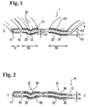
- FIGs. 1 - 4(f) is explanatory schematic views.
- a plate thickness, a dimension of a sealing groove and a length to width ratio of the cylinder head gasket are different from the actual ones for a demonstration purpose.
- the cylinder head gasket 1 of the first embodiment according to the present invention is formed of a metal base plate 10 made of annealed stainless steel, heat-treated stainless steel (spring steel), soft steel or the like.
- the metal base plate 10 is formed to fit a shape of an engine member, such as a cylinder block, and a plurality of cylinder bores 2, fluid holes 3, 4, bolt holes 5 for tightening bolts and the like are formed therein.
- a grommet 11 made of an annealed stainless steel plate, soft steel plate or copper plate with a thickness of 0.1 mm - 0.15 mm to constitute a primary sealing portion S1.
- a full bead 12 is provided outside the primary sealing portion S1, and a foamed silicone resin containing micro capsules is coated on both sides of the full bead 12 in a belt shape.
- the foamed silicone resin is coated by screen printing at a foaming ratio of 200% to 300% to form foamed coating layers 22 having a thickness t2 of 100 ⁇ m - 200 ⁇ m and a width of 1 mm - 5 mm to cover the full bead 12.
- a secondary sealing portion S2 is formed of the full bead 12 and the foamed coating layers 22 provided on both sides of the full bead 12.
- a half bead 13 is provided on a part of the fluid holes 3, such as a cooling water hole and oil hole.
- the foamed silicone resin containing the micro capsules is coated in a belt shape on both sides of the half bead 13 by the screen printing at a foaming ratio of 200% - 300% to form a foamed coating layer 23 having a thickness t3 of 60 ⁇ m - 150 ⁇ m and a width of 1 mm - 5 mm to cover the half bead 13.
- a fluid hole sealing portion S3 is formed of the half bead 13 and the foamed coating layers 23 provided on both sides of the half bead 13.
- the thickness t2 of the foamed coating layer 22 in the secondary sealing portion S2 is formed to be thicker than the thickness t3 of the foamed coating layer 23 of the fluid hole sealing portion S3. Also, the foaming ratio of the foamed coating layer 23 around the fluid hole sealing portion may be greater than that of the foamed coating layer 22 in the secondary sealing portion.
- a micro seal coating layer 30 having a hardness of H - 2B in pencil hardness is formed by coating a material, such as NBR rubber and fluoro rubber on substantially whole surfaces on both sides of the gasket 1 through the screen printing.
- the dimensions of a plate thickness and the like are, for example, as follows; a diameter of a cylinder bore is 80 mm, the thickness t1 of the metal base plate 10 is 0.15 - 0.4 mm; a height h1 of the full bead 12 for the cylinder bore 2 is 0.2 - 0.3 mm; a height h2 of the half bead 13 for the fluid hole 3 is 0.2 - 0.4 mm; the thickness t2 of the foamed coating layer 22 is 100 - 200 ⁇ m; the thickness t3 of the foamed coating layer 23 is 60 - 150 ⁇ m; and a thickness t4 of the micro seal coating 30 is 10 - 30 ⁇ m.
- Figs. 3(a) - 3(f) show embodiments of the primary sealing portion S1, wherein in Figs. 3(a) and 3(b), grommets 11, 11A are provided, respectively; in Fig. 3(c) and 3(d), a shim 41 is provided only on one side of the metal base plate; and in Fig. 3(e) and 3(f), shims 41, 41 are provided on both sides of the metal base plate.
- the shim 41 has a thickness of 0.03 - 0.1 mm and is made of a material, such as annealed stainless steel, soft steel or copper.
- Figs. 4(a) - 4(f) show embodiments of the secondary sealing portion S2 and the fluid hole sealing portion S3.
- Fig. 4(a) shows a structure of the full bead 15 and the foamed coating layers 25 applied to both sides;
- Fig. 4(b) and Fig. 4(c) show structures of the full bead 15 and the foamed coating layer 25 applied only on one side, respectively;
- Fig. 4(d) shows a structure of the half bead 16 and the foamed coating layers 26 applied on both sides;
- Figs. 4(e) and 4(f) show a structure of the half beads 16 and the foamed coating layer 26 applied only on one side, respectively.
- the shape of the full bead 15 is represented by a circular arc shape, its shape may be a trapezoid or other shape, and the half bead 16 may also be a shape other than the one shown in the figures.
- the cylinder head gasket with a necessary sealing ability depending on a type of the engine can be designed through a combination of the primary sealing portion S1, the secondary sealing portion S2, the fluid hole sealing portion S3, with or without the micro seal coating 30, and the one-side coating or the both-side coating.
- the following effects can be obtained. Since a combination of the hard primary sealing potion with a good heat and creep resistance, and the soft secondary sealing portion with a good fitting ability is provided around a cylinder bore, a high sealing ability can be obtained.
- the first sealing portion since the primary sealing portion close to the combustion chamber is formed of the grommet or shim made of metal, the first sealing portion has an excellent heat resistance. Also, since the primary sealing portion is made of the hard metal, it has an excellent creep resistance to prevent an excessive decrease in torque. Moreover, the first sealing portion protects the second sealing portion.
- the foamed coating layer provided in the secondary sealing portion is thicker than the micro seal coating layer, a step produced by the primary sealing portion can be covered.
- a scratch, such as a V-notch, larger than a tool mark formed on the sealing surface of the member, i.e. cylinder head, can be covered by the foamed coating layer, which is relatively soft and has a fitting property, so that a good sealing ability can be obtained.
- the fluid hole sealing portion is formed of the same bead and foamed coating layer as those in the secondary sealing portion, the fluid hole sealing portion can be formed at the same time in the same process as the secondary sealing portion, thus an additional production processes is eliminated to thereby reduce a production cost.
Landscapes
- Engineering & Computer Science (AREA)
- General Engineering & Computer Science (AREA)
- Mechanical Engineering (AREA)
- Chemical & Material Sciences (AREA)
- Combustion & Propulsion (AREA)
- Gasket Seals (AREA)
Applications Claiming Priority (2)
| Application Number | Priority Date | Filing Date | Title |
|---|---|---|---|
| JP2001213608 | 2001-07-13 | ||
| JP2001213608A JP2003028300A (ja) | 2001-07-13 | 2001-07-13 | シリンダヘッドガスケット |
Publications (2)
| Publication Number | Publication Date |
|---|---|
| EP1275889A2 true EP1275889A2 (de) | 2003-01-15 |
| EP1275889A3 EP1275889A3 (de) | 2004-01-21 |
Family
ID=19048553
Family Applications (1)
| Application Number | Title | Priority Date | Filing Date |
|---|---|---|---|
| EP02014941A Withdrawn EP1275889A3 (de) | 2001-07-13 | 2002-07-08 | Zylinderkopfdichtung |
Country Status (4)
| Country | Link |
|---|---|
| US (1) | US6682080B2 (de) |
| EP (1) | EP1275889A3 (de) |
| JP (1) | JP2003028300A (de) |
| KR (1) | KR20030007042A (de) |
Cited By (5)
| Publication number | Priority date | Publication date | Assignee | Title |
|---|---|---|---|---|
| EP1544518A1 (de) * | 2003-12-19 | 2005-06-22 | Ishikawa Gasket Co. Ltd. | Zylinderkopfdichtung |
| US6981703B2 (en) | 2003-12-17 | 2006-01-03 | Ishikawa Gasket Co., Ltd. | Cylinder head gasket |
| WO2006079452A1 (de) * | 2005-01-26 | 2006-08-03 | Reinz-Dichtungs-Gmbh | Metallische flachdichtung |
| WO2009152815A1 (de) | 2008-06-21 | 2009-12-23 | Federal-Mogul Sealing Systems Gmbh | Flachdichtung |
| EP1908999A4 (de) * | 2005-07-21 | 2012-03-28 | Nok Corp | Verfahren zur herstellung von metalldichtungen |
Families Citing this family (25)
| Publication number | Priority date | Publication date | Assignee | Title |
|---|---|---|---|---|
| KR100549913B1 (ko) * | 2002-04-04 | 2006-02-06 | 니혼 메타루 가스켓토 가부시키가이샤 | 금속개스킷 |
| JP2004308761A (ja) * | 2003-04-07 | 2004-11-04 | Uchiyama Mfg Corp | 多機能ガスケット |
| US20050046120A1 (en) * | 2003-08-28 | 2005-03-03 | Martin Novil | Sealing gasket with flexible stopper |
| CA2477342A1 (en) * | 2003-08-28 | 2005-02-28 | Freudenberg-Nok General Partnership | Improved sealing gasket with flexible stopper |
| US7234705B2 (en) * | 2003-08-28 | 2007-06-26 | Freudenberg-Nok General Partnership | Sealing gasket with flexible stopper |
| JP3908745B2 (ja) * | 2004-03-09 | 2007-04-25 | 石川ガスケット株式会社 | 金属積層形ガスケット |
| JP2005315417A (ja) * | 2004-03-30 | 2005-11-10 | Nichias Corp | 金属ガスケット |
| US7771817B2 (en) * | 2004-03-31 | 2010-08-10 | Nichias Corporation | Gasket material |
| JP4773120B2 (ja) * | 2004-03-31 | 2011-09-14 | ニチアス株式会社 | ガスケット用素材 |
| US20060012070A1 (en) * | 2004-07-13 | 2006-01-19 | Nordson Corporation | Gasket assembly |
| US7070187B2 (en) * | 2004-11-09 | 2006-07-04 | Federal-Mogul World Wide, Inc | Gasket assembly |
| US7401790B2 (en) * | 2005-01-11 | 2008-07-22 | Federal-Mogul World Wide, Inc. | Metal gasket with rigid seal |
| US20090033039A1 (en) * | 2005-06-28 | 2009-02-05 | Freudenberg-Nok General Partnership | Gasket with asymmetric bead arrangement |
| JP4137146B2 (ja) * | 2006-07-21 | 2008-08-20 | トヨタ自動車株式会社 | ガスケット |
| JP4721974B2 (ja) * | 2006-07-27 | 2011-07-13 | ヤマハ発動機株式会社 | メタルガスケット |
| US7806413B2 (en) * | 2006-11-08 | 2010-10-05 | Federal-Mogul Corporation | Static gasket |
| JP5024126B2 (ja) * | 2008-03-07 | 2012-09-12 | 日本ガスケット株式会社 | シリンダヘッドガスケット |
| US8579299B2 (en) * | 2009-04-03 | 2013-11-12 | Interface Solutions, Inc. | Gasket having adhesive element |
| JP5653695B2 (ja) * | 2010-09-10 | 2015-01-14 | 三菱重工業株式会社 | ガスケット及び電動圧縮機 |
| WO2017090702A1 (ja) * | 2015-11-27 | 2017-06-01 | Nok株式会社 | 金属ガスケット |
| DE102016201877A1 (de) * | 2016-02-08 | 2017-08-10 | Elringklinger Ag | Zylinderkopfdichtung |
| EP3822531A1 (de) | 2019-11-14 | 2021-05-19 | FH Münster - University of Applied Sciences | Dichtungsring und flanschverbindung mit solch einem dichtungsring |
| WO2021166442A1 (ja) * | 2020-02-17 | 2021-08-26 | Nok株式会社 | ガスケット製造方法 |
| JP7446930B2 (ja) * | 2020-06-17 | 2024-03-11 | 株式会社Subaru | ガスケット |
| US12370763B2 (en) * | 2022-04-21 | 2025-07-29 | Caterpillar Inc. | Method and tool for controlled application of sealant material |
Family Cites Families (14)
| Publication number | Priority date | Publication date | Assignee | Title |
|---|---|---|---|---|
| DE3373129D1 (en) * | 1982-05-17 | 1987-09-24 | Nihon Metal Gasket | Single metallic plate gasket |
| DE3500071A1 (de) * | 1985-01-03 | 1986-07-03 | Elring Dichtungswerke Gmbh, 7012 Fellbach | Zylinderkopfdichtung |
| US5435575A (en) * | 1988-08-11 | 1995-07-25 | Ishikawa Gasket Co., Ltd. | Steel laminate gasket |
| US4968045A (en) * | 1988-11-22 | 1990-11-06 | Nippon Leakless Industry Co., Ltd. | Metal gasket |
| DE69209009T2 (de) * | 1991-11-25 | 1996-08-29 | Taiho Kogyo Co Ltd | Metalldichtung |
| JP3393876B2 (ja) * | 1991-12-27 | 2003-04-07 | 大豊工業株式会社 | 金属ガスケットの製造方法 |
| JPH0632836U (ja) * | 1992-09-29 | 1994-04-28 | ニチアス株式会社 | ヘッドガスケット |
| US5582415A (en) * | 1993-08-31 | 1996-12-10 | Kokusan Parts Industry Co., Ltd. | Metal gasket |
| US5938208A (en) * | 1994-12-30 | 1999-08-17 | Kokusan Parts Industry Co., Ltd. | Separate plate placed between adjacent valve bodies in a control valve unit of an automatic transmission |
| JP2929450B2 (ja) * | 1995-06-01 | 1999-08-03 | 石川ガスケット株式会社 | 上下一対の板で構成した内燃機関用金属積層形ガスケット |
| DE19523759A1 (de) * | 1995-06-29 | 1997-01-02 | Friedhelm Stecher | Flachdichtung und Verfahren zu ihrer Herstellung |
| US5769430A (en) * | 1996-09-30 | 1998-06-23 | Ishikawa Gasket Co., Ltd. | Metal gasket with bead and thermal sprayed layer thereof |
| JP2002013640A (ja) * | 2000-06-29 | 2002-01-18 | Uchiyama Mfg Corp | シリンダヘッドガスケット |
| JP2002054745A (ja) * | 2000-08-07 | 2002-02-20 | Ishikawa Gasket Co Ltd | ヘッドガスケット |
-
2001
- 2001-07-13 JP JP2001213608A patent/JP2003028300A/ja active Pending
-
2002
- 2002-07-08 KR KR1020020039265A patent/KR20030007042A/ko not_active Ceased
- 2002-07-08 EP EP02014941A patent/EP1275889A3/de not_active Withdrawn
- 2002-07-12 US US10/193,184 patent/US6682080B2/en not_active Expired - Fee Related
Cited By (6)
| Publication number | Priority date | Publication date | Assignee | Title |
|---|---|---|---|---|
| US6981703B2 (en) | 2003-12-17 | 2006-01-03 | Ishikawa Gasket Co., Ltd. | Cylinder head gasket |
| EP1544518A1 (de) * | 2003-12-19 | 2005-06-22 | Ishikawa Gasket Co. Ltd. | Zylinderkopfdichtung |
| WO2006079452A1 (de) * | 2005-01-26 | 2006-08-03 | Reinz-Dichtungs-Gmbh | Metallische flachdichtung |
| EP1908999A4 (de) * | 2005-07-21 | 2012-03-28 | Nok Corp | Verfahren zur herstellung von metalldichtungen |
| WO2009152815A1 (de) | 2008-06-21 | 2009-12-23 | Federal-Mogul Sealing Systems Gmbh | Flachdichtung |
| CN101910689A (zh) * | 2008-06-21 | 2010-12-08 | 菲特尔莫古密封系统有限公司 | 平面密封件 |
Also Published As
| Publication number | Publication date |
|---|---|
| JP2003028300A (ja) | 2003-01-29 |
| US6682080B2 (en) | 2004-01-27 |
| EP1275889A3 (de) | 2004-01-21 |
| US20030011139A1 (en) | 2003-01-16 |
| KR20030007042A (ko) | 2003-01-23 |
Similar Documents
| Publication | Publication Date | Title |
|---|---|---|
| US6682080B2 (en) | Cylinder head gasket | |
| US5791659A (en) | Metal gasket | |
| US6783132B2 (en) | Cylinder head gasket with seal coatings | |
| EP1180622B1 (de) | Zylinderkopfdichtung mit teilweiser Kunstharzbeschichtung | |
| US20080164659A1 (en) | Metal gasket | |
| JP2004293596A (ja) | メタルガスケット | |
| JP3753413B2 (ja) | 多気筒用のヘッドガスケット | |
| US5370406A (en) | Metallic laminate gasket with plates of different bead widths fixed together | |
| US6893023B2 (en) | Metal gasket with partial coating | |
| EP0787934B1 (de) | Mehrschichtige Metalldichtung mit verschiedenen Überzugsschichten | |
| EP0833086B1 (de) | Metallabdichtung mit Deckschicht | |
| EP0892199A2 (de) | Mehrlagenmetalldichtung mit breiten und schmalen Flanschabschnitten | |
| EP1306588B1 (de) | Metalldichtung mit einer partiellen Oberflächenbeschichtung | |
| KR0174743B1 (ko) | 넓은 밀봉구역을 가진 강박판 적층 개스킷 | |
| US7669859B2 (en) | Cylinder head gasket | |
| US6981703B2 (en) | Cylinder head gasket | |
| EP0508017B1 (de) | Flachdichtung aus Metalllaminat mit einer Graphitschicht | |
| EP0431227A1 (de) | Stahllaminatdichtung | |
| EP1180621A2 (de) | Zylinderkopfdichtung mit partieller Kunstharzschicht | |
| US20020014745A1 (en) | Cylinder head gasket with step regulation layer | |
| US7014194B2 (en) | Cylinder head gasket | |
| EP1544518B1 (de) | Zylinderkopfdichtung | |
| JP3769523B2 (ja) | シリンダヘッドガスケット | |
| JP3549016B2 (ja) | ガスケット | |
| JPH05149438A (ja) | シリンダヘツドガスケツト |
Legal Events
| Date | Code | Title | Description |
|---|---|---|---|
| PUAI | Public reference made under article 153(3) epc to a published international application that has entered the european phase |
Free format text: ORIGINAL CODE: 0009012 |
|
| AK | Designated contracting states |
Kind code of ref document: A2 Designated state(s): AT BE BG CH CY CZ DE DK EE ES FI FR GB GR IE IT LI LU MC NL PT SE SK TR |
|
| AX | Request for extension of the european patent |
Free format text: AL;LT;LV;MK;RO;SI |
|
| PUAL | Search report despatched |
Free format text: ORIGINAL CODE: 0009013 |
|
| AK | Designated contracting states |
Kind code of ref document: A3 Designated state(s): AT BE BG CH CY CZ DE DK EE ES FI FR GB GR IE IT LI LU MC NL PT SE SK TR |
|
| AX | Request for extension of the european patent |
Extension state: AL LT LV MK RO SI |
|
| 17P | Request for examination filed |
Effective date: 20040105 |
|
| 17Q | First examination report despatched |
Effective date: 20040416 |
|
| AKX | Designation fees paid |
Designated state(s): DE FR GB IT |
|
| GRAP | Despatch of communication of intention to grant a patent |
Free format text: ORIGINAL CODE: EPIDOSNIGR1 |
|
| STAA | Information on the status of an ep patent application or granted ep patent |
Free format text: STATUS: THE APPLICATION IS DEEMED TO BE WITHDRAWN |
|
| 18D | Application deemed to be withdrawn |
Effective date: 20060315 |