EP1275750A2 - Bedampfungsanlage - Google Patents
Bedampfungsanlage Download PDFInfo
- Publication number
- EP1275750A2 EP1275750A2 EP02010092A EP02010092A EP1275750A2 EP 1275750 A2 EP1275750 A2 EP 1275750A2 EP 02010092 A EP02010092 A EP 02010092A EP 02010092 A EP02010092 A EP 02010092A EP 1275750 A2 EP1275750 A2 EP 1275750A2
- Authority
- EP
- European Patent Office
- Prior art keywords
- electron beam
- deflection
- deflected
- time
- periodicity
- Prior art date
- Legal status (The legal status is an assumption and is not a legal conclusion. Google has not performed a legal analysis and makes no representation as to the accuracy of the status listed.)
- Granted
Links
Images


Classifications
-
- C—CHEMISTRY; METALLURGY
- C23—COATING METALLIC MATERIAL; COATING MATERIAL WITH METALLIC MATERIAL; CHEMICAL SURFACE TREATMENT; DIFFUSION TREATMENT OF METALLIC MATERIAL; COATING BY VACUUM EVAPORATION, BY SPUTTERING, BY ION IMPLANTATION OR BY CHEMICAL VAPOUR DEPOSITION, IN GENERAL; INHIBITING CORROSION OF METALLIC MATERIAL OR INCRUSTATION IN GENERAL
- C23C—COATING METALLIC MATERIAL; COATING MATERIAL WITH METALLIC MATERIAL; SURFACE TREATMENT OF METALLIC MATERIAL BY DIFFUSION INTO THE SURFACE, BY CHEMICAL CONVERSION OR SUBSTITUTION; COATING BY VACUUM EVAPORATION, BY SPUTTERING, BY ION IMPLANTATION OR BY CHEMICAL VAPOUR DEPOSITION, IN GENERAL
- C23C14/00—Coating by vacuum evaporation, by sputtering or by ion implantation of the coating forming material
- C23C14/22—Coating by vacuum evaporation, by sputtering or by ion implantation of the coating forming material characterised by the process of coating
- C23C14/54—Controlling or regulating the coating process
-
- C—CHEMISTRY; METALLURGY
- C23—COATING METALLIC MATERIAL; COATING MATERIAL WITH METALLIC MATERIAL; CHEMICAL SURFACE TREATMENT; DIFFUSION TREATMENT OF METALLIC MATERIAL; COATING BY VACUUM EVAPORATION, BY SPUTTERING, BY ION IMPLANTATION OR BY CHEMICAL VAPOUR DEPOSITION, IN GENERAL; INHIBITING CORROSION OF METALLIC MATERIAL OR INCRUSTATION IN GENERAL
- C23C—COATING METALLIC MATERIAL; COATING MATERIAL WITH METALLIC MATERIAL; SURFACE TREATMENT OF METALLIC MATERIAL BY DIFFUSION INTO THE SURFACE, BY CHEMICAL CONVERSION OR SUBSTITUTION; COATING BY VACUUM EVAPORATION, BY SPUTTERING, BY ION IMPLANTATION OR BY CHEMICAL VAPOUR DEPOSITION, IN GENERAL
- C23C14/00—Coating by vacuum evaporation, by sputtering or by ion implantation of the coating forming material
- C23C14/22—Coating by vacuum evaporation, by sputtering or by ion implantation of the coating forming material characterised by the process of coating
- C23C14/24—Vacuum evaporation
- C23C14/28—Vacuum evaporation by wave energy or particle radiation
- C23C14/30—Vacuum evaporation by wave energy or particle radiation by electron bombardment
Definitions
- the invention relates to a device for deflecting an electron beam and a device Vacuum deposition system with such a device and a method for operation the same.
- BOC Coating Technology sells a "Temescal Bipolar Sweep" Beam deflection system in which the deflection is sinusoidal in both coordinate directions Can be triangular (with adjustable fixed amplitude and adjustable fixed offset). The two deflection frequencies can be different or the same. Only at The beam deflection is synchronous in both coordinate directions. It are eight presettable parameter sets (amplitude, frequency, offset, each for the X and the Y direction), between which you can switch during the steaming process.
- the object of the invention was to provide a vacuum vapor deposition system in which the symmetry and the durability of the steam lobe are improved. Furthermore, the invention was based on the object of reducing the production costs of thin layers in that the erosion takes place more uniformly on the sample. Furthermore, the invention was based on the object of making the electron beam deflection more convenient.
- a symmetrical steam cloud that remains constant during operation has an effect advantageous to and from a uniform layer thickness on the substrates to be coated other vaporizing material in a crucible can be almost completely be used up, which results in a cost advantage.
- This cost advantage has the same effect the more expensive the evaporation materials are.
- a device with which a particularly even burn-off could be achieved by the measure selected according to the electron beam in two coordinate directions Deflect functions by controlling deflection modules can be realized Measure, at least one of these selected functions with a changing time Providing term, it became possible to change the electron beam with time To deflect periodicities. This is particularly advantageous for curves having crucible shapes.
- the committee can, in particular, be able to carry out the selected functions be reduced.
- Electron beam deflections in the X and Y directions are coordinated in time, i.e. phase-locked, to expire.
- This timing coordination can e.g. achieved by a trigger signal are controlled by the electron beam deflection depending on the trigger signal becomes.
- a small wobble can also be provided. With such a wobble one can particularly even burn-off due to the surface of the evaporation material impinging electrons can be reached.
- Another variant of the invention uses sine and cosine in the X and Y directions fixed frequency and a variable amplitude A (t).
- a (t) the Beam intensity increases, so that the beam accelerates the evaporation material at the edge of the crucible erodes.
- the level in the crucible is changed each time the Electron beam lowered by the same amount at every point, although the beam of some places, especially in the edge area of the crucible, strokes the evaporation material more quickly.
- Yet another variant of the invention changes the focus of the electron beam depending on the speed components in the X and Y direction with the aim that the Evaporation material is removed evenly.
- the device for deflecting an electron beam comprises a control device, whereby the deflection modules associated with the electron beam according to selected functions can be controlled in two coordinate directions. This allows the electron beam deflected in two coordinate directions depending on the current position become.
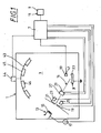
- the vacuum deposition system 1 shown in FIG. 1 has one Vacuum chamber 3 in which an electron source 13 for generating an electron beam 14 is arranged.
- a glow wire 15 is provided as the electron source 13 Voltage source 17 and a grid 19 are assigned so that by applying a voltage between the glow wire and the grid the electrons emitted by 15 towards the grid 19 be accelerated.
- the grid is in turn provided with an adjustable diaphragm 21, so that the electrons accelerated towards the grid are focused through the aperture and thereby generating the electron beam 14.
- the electromagnet 29 includes, authoritative.
- the deflection modules 23, 27 become a control program controlled deflection of the electron beam.
- the control program is based on a Embodiment with a round crucible described in more detail below. This Control program is stored in a CPU 101, which is part of a control device 7.
- the setting of the adjustable diaphragm 21 is also carried out by this control device 7 and the voltage for accelerating the electrons emitted by the filament 15 are controlled.
- the electron beam 14 is on a crucible 31, which is filled with material 33 to be evaporated is directed, as shown in more detail in Figure 2.
- This crucible 31 is a detector 39, such as for example a quartz crystal 41 for the detection of the vaporized material or Detection of the evaporation rate of the evaporation material 33 assigned.
- a cap 46 is arranged, which to coating substrates 45, such as or lenses, the surfaces 46 of which are to be coated, wearing.
- the cap 46 can be driven in rotation by an associated motor 44, the Motor is controlled by the control device 7.
- the control device 7 is a Operating unit 9, which is configured here in the form of a display 11, is assigned. About this Display 11 can be used to make settings that are made by means of the control device 7 be carried out. These settings can be made both before and during the Evaporation process can be made.
- the crucible 31, in which the material 33 to be evaporated is received shown.
- the material 33 to be evaporated is evaporated by means of the electron beam 14.
- a vapor cloud 35 is formed.
- the evaporation material evenly removed. This removal is also referred to as erosion 37.
- FIG. 3 shows an advantageous embodiment of the control device 7 for providing the beam deflection according to the invention.
- This control device 7 Voltage signals 118, 119 generated, which on the deflection modules 23, 27 for deflecting the Apply electron beam.
- the control device 7 contains a CPU core 101 with one required read-only memory, main memory and control program.
- the CPU core includes ROM and RAM.
- the CPU core 101 has access to a programmable one Timer 102, which periodically sends interrupts to CPU core 101 and on provides higher frequency periodic signal for a programmable counter 103.
- a plurality of digital-to-analog converters 103-108 are connected to the CPU core 101.
- the CPU core 101 receives interrupts from the in short periodic intervals programmable timer 102 and loads new ones depending on the interrupts received Output values in the two digital-to-analog converters 104, 105. This roughly becomes one Deflection of the electron beam 14 controlled in the Y and X directions.
- the output values can be stored in a memory or by means of stored functions which are stored in the CPU can be generated.
- a RAM and / or ROM arranged in the CPU can be used as memory be provided.
- the programmable counter 103 includes a coaster that ensures that the counter 103 at every nth, e.g. 1000th pulse, on which clock input 100 counts by one.
- the reduction factor n is specified by the CPU core as a function of time. After reaching one Maximum value, e.g. of the number 4095, the counter is reset with the next nth clock pulse reset to a starting value, preferably to zero.
- the counter outputs are included ROM modules 109, 110 in connection, the outputs of which each have downstream digital-to-analog converters 111, 112 are in signal connection.
- a sine and a cosine signal are generated via these outputs of the digital / analog converter 111, 112 output.
- the frequency and phase position of these output signals are determined by the Programmable counters 103 are matched to each other and are thus mutually related to each Coordinated time. This is also known as phase locked.
- the amplitude of the sine and cosine function is determined by means of the digital-to-analog converter 106 and via the reference inputs connected to the digital-to-analog converters 111, 112 set programmatically.
- the entire function block 113 serves the purpose of the two digital-to-analog converters 104, 105 induced gross deflection of the electron beam 14 to overlay a sweep.
- the electron beam 14 is generated according to one Voltage signal deflected by the deflection modules 23, 27. Of course you can Generation of a swept voltage signal for deflecting the electron beam 14 also periodic functions other than sine and cosine functions can be used.
- the two wobble signals go to two output stages via the summation amplifiers 114, 115 116, 117.
- the output stages 116, 117 generate from the two swept input voltages corresponding control currents 118, 119 which the deflection modules 27 for deflecting the Electron beam in the X and Y directions are supplied.
- a control program is stored in the CPU core, which is controlled by the Interrupt from the programmable timer 102 is periodically activated.
- the Number of calls in the control program in a variable v continuously up to one Maximum number m counted. In the subsequent interrupt, it resets the counter v to zero.
- the variable v is therefore proportional to the time modulo a repetition interval that in the Example shown in Figure 4 is 1000 time units.
- the electron beam 14 is now guided according to an Archimedean spiral 47 over the evaporation material 33, the speed being controlled so that the electron beam 14 travels the same path lengths at the same time intervals.
- the Archimedean spiral is shown in FIG 47, which the electron beam 14 travels on the evaporation substrate 33 when the CPU core after calculating rho [v] calculates the output values x (rho) and in the Stores analog-to-digital converter 104 and stores y (rho) in the analog-to-digital converter 105.
- an additive offset value that does not change over time is also taken into account, which affects the center position 49 of the Archimedean spiral 47.
- Figure 5 e.g. every 500th distraction value as thick dot is drawn, with a correspondingly large repetition interval of v selected has been.
- the points along the curve have the same Distances, which means a constant speed with respect to the distance covered deflected electron beam 14 and does not correspond to the swept angle.
- the Angular velocity of the electron beam is targeted in this embodiment variable.
- This picture shows the basic course of the beam when wobbling over the digital-to-analog converter 106 is switched off.
- the spiral becomes one Small amplitude gyroscopic movement - e.g. in the order of the spiral arm distance 2 * Phi * a overlaid.
- This exemplary embodiment explained in detail here shows a particularly advantageous control of the electron beam 14 for a round crucible 31.
- the invention is not limited to round crucible 31 to understand.
- the Archimedean spiral 47 is one select suitable beam guidance for the crucible shape used.
- an oval Crucible with a rough guidance of the electron beam along an elliptical path changing radii.
- the CPU 101 is assigned a memory unit ROM, in which for various Evaporation materials are assigned values by which the speed and the intensity with which the electron beam 14 travels the evaporation material 33 is stored are.
Landscapes
- Chemical & Material Sciences (AREA)
- Chemical Kinetics & Catalysis (AREA)
- Engineering & Computer Science (AREA)
- Materials Engineering (AREA)
- Mechanical Engineering (AREA)
- Metallurgy (AREA)
- Organic Chemistry (AREA)
- Health & Medical Sciences (AREA)
- Toxicology (AREA)
- Physical Vapour Deposition (AREA)
Abstract
Description
Weiterhin lag der Erfindung die Aufgabe zugrunde, die Herstellkosten von dünnen Schichten zu senken, indem der Abbrand auf der Probe gleichmäßiger stattfindet.
Weiterhin lag der Erfindung die Aufgabe zugrunde, die Elektronenstrahlauslenkung komfortabler zu gestalten.
- Koordinierte Ablenkung des Strahls in beide Koordinatenrichtungen,
- gleichzeitig Änderung der Strahlintensität und der Fokussierung des Elektronenstrahls.
Dies kann alles programmgesteuert durchgeführt werden, so daß das Verdampfungsmaterial gleichmäßig abgetragen wird.
- Figur 1:
- Vakuumbedampfungsanlage;
- Figur 2:
- Tiegel;
- Figur 3:
- Blockschaltbild der Elektronenstrahlablenkung;
- Figur 4:
- Darstellung der pragrammierbaren Zählung und
- Figur 5:
- graphische Darstellung der Elektronenstrahlablenkung bei einem runden Tiegel
- 1.
- Vakuumbedampfungsanlage
- 2.
- Vakuumkammer
- 7.
- Steuereinrichtung
- 9.
- Bedieneinheit
- 11.
- Display
- 13.
- Elektronenquelle
- 14.
- Elektronenstrahl
- 15.
- Glühdraht
- 17.
- Spannungsquelle
- 19.
- Gitter
- 21.
- (verstellbare) Blende
- 23.
- Ablenkmodul
- 47.
- Archimedische Spirale
- 49.
- Mittelpunkt
- 51.
- 500-ster Ablenkwert
- 100
- clock-Eingang
- 101
- CPU-Kern
- 102
- programmierbarer Zeitgeber
- 103
- programmierbarer Zähler
- 103
- Digital-/Analogwandler (D/A Wandler)
- 104
- D/A Wandler
- 105
- D/A Wandler
- 106
- D/A Wandler
- 107
- D/A Wandler
- 108
- D/A Wandler
- 109
- ROM
- 110
- ROM
- 111
- D/A Wandler
- 112
- D/A Wandler
- 113
- Funktionsblock
- 114
- Summationsverstärker
- 25.
- Elektromagnete
- 27.
- Ablenkmodul
- 29.
- Elektromagnete
- 31.
- Tiegel
- 33.
- Verdampfungsmaterial
- 35.
- Dampfwolke
- 37.
- Abbrand
- 39.
- Detektor
- 41.
- Schwingquarz
- 43.
- Kalotte
- 44.
- Motor
- 45.
- Substrat
- 46.
- Linsenoberfläche
- 115
- Summationsverstärker
- 116
- Endstufe
- 117
- Endstufe
- 118
- Steuerstrom
- 119
- Steuerstrom
- 120
- Endstufe
- 121
- Endstufe
Claims (18)
- Vorrichtung zur Herstellung dünner Schichten in einer Vakuumanlage mit einer Steuereinrichtung zur Auslenkung eines Elektronenstrahls, der Ablenkmodule zugeordnet sind, die gemäß jeweils ausgewählter Funktionen ansteuerbar sind, wobei durch deren Ansteuerung der Elektronenstrahl in zwei Koordinatenrichtungen auslenkbar ist, dadurch gekennzeichnet, daß mindestens eine der ausgewählten Funktionen einen sich zeitlich ändernden Term umfaßt, durch den sich die Periodizität der Auslenkung des Elektronenstrahls (14) bzgl. dieser Koordinatenrichtung ändert.
- Vorrichtung nach Anspruch 1, dadurch gekennzeichnet, daß der Term, durch den der Elektronenstrahl in mindestens eine der Koordinatenrichtungen mit sich zeitlich ändernder Periodizität ausgelenkt wird, mittels einer während des Aufdampfprozesses manuell bedienbaren Eingabeeinheit generiert wird.
- Vorrichtung nach Anspruch 1, dadurch gekennzeichnet, daß der Term, durch den der Elektronenstrahl in mindestens eine der Koordinatenrichtungen mit sich zeitlich ändernder Periodizität ausgelenkt wird, automatisiert durch die Steuereinrichtung vorgegeben wird.
- Vorrichtung nach Anspruch 2 oder 3, dadurch gekennzeichnet, daß der Term einen programmierbaren, zeitlich veränderbaren Faktor umfaßt.
- Vorrichtung nach Anspruch 2 oder 3, dadurch gekennzeichnet, daß mindestens eine der ausgewählten Funktionen zeitlich veränderbarer Amplitudenterme umfaßt.
- Vorrichtung nach mindestens einem der Ansprüche 1-5, dadurch gekennzeichnet, daß der Term für die zeitlich veränderbare Auslenkung jeweils von dem Verdampfungsmaterial abhängig festgelegt ist.
- Vorrichtung nach mindestens einem der vorangegangenen Ansprüche, dadurch gekennzeichnet, daß die Intensität des Elektronenstrahls (14) variierbar ist.
- Verfahren zur Herstellung dünner Schichten in einer Vakuumanlage, bei der ein Elektronenstrahl in zwei Koordinatenrichtungen ausgelenkt wird, dadurch gekennzeichnet, daß der Elektronenstrahl (14) in mindestens einer Koordinatenrichtung mit einer sich zeitlich ändernden Periodizität ausgelenkt wird.
- Verfahren zum Verdampfen von Material mittels eines Elektronenstrahls, wobei der Elektronenstrahl in eine erste und eine zweite Koordinatenrichtung ( x und y oder radial und tangential) ausgelenkt wird, dadurch gekennzeichnet, daß der Elektronenstrahl in die erste und zweite Koordinatenrichtung zeitlich koordiniert ausgelenkt wird und daß die Elektronenstrahlauslenkung eine kleine Wobbelung überlagert ist.
- Verfahren nach Anspruch 8 oder 9, dadurch gekennzeichnet, daß der Elektronenstrahl in mindestens einer Koordinatenrichtung mit sich zeitlich ändernder Amplitude ausgelenkt wird.
- Verfahren nach mindestens einem der vorangegangen Verfahrensansprüche, dadurch gekennzeichnet, daß die Auslenkung des Elektronenstrahls in die unterschiedlichen Koordinatenrichtungen mit unterschiedlicher Geschwindigkeit erfolgt, wobei einer niederfrequenten Grundauslenkung, eine hochfrequente, als Wobbelung bezeichnete Auslenkung, überlagert wird.
- Verfahren nach einem der vorangegangenen Verfahrensansprüche, daß die zeitliche Änderung von Periodizität und/oder Amplitude in Abhängigkeit von der momentanen Position des Elektronenstrahls abhängig gesteuert wird.
- Verfahren nach Anspruch 9, dadurch gekennzeichnet, daß die Frequenz der Grundauslenkung im Bereich von 4 - 150 Hz liegt.
- Verfahren nach Anspruch 9 oder 11, dadurch gekennzeichnet, daß die Frequenz der Wobbelung im Bereich von 50-500 Hz liegt.
- Verfahren nach einem der vorangegangenen Verfahrensansprüche, dadurch gekennzeichnet, daß der Elektronenstrahl mit konstanter Geschwindigkeit bezüglich der zurückgelegten Strecke das abzubrennende Verdampfungsmaterial überstreift.
- Verfahren nach einem der vorangegangenen Verfahrensansprüche, dadurch gekennzeichnet, daß die Strahlintensität variiert wird.
- Computerprogramm zum Betreiben einer Vakuumbedampfungsanlage, durch das die Auslenkung eines Elektronenstrahls gemäß dem Verfahren nach einem der Ansprüche 7-15 gesteuert wird.
- Vakuumverdampfungsanlage, die gemäß einem der vorangegangenen Verfahrensansprüche betreibbar ist.
Applications Claiming Priority (2)
| Application Number | Priority Date | Filing Date | Title |
|---|---|---|---|
| DE10133748 | 2001-07-11 | ||
| DE10133748 | 2001-07-11 |
Publications (3)
| Publication Number | Publication Date |
|---|---|
| EP1275750A2 true EP1275750A2 (de) | 2003-01-15 |
| EP1275750A3 EP1275750A3 (de) | 2007-04-04 |
| EP1275750B1 EP1275750B1 (de) | 2009-07-01 |
Family
ID=7691432
Family Applications (1)
| Application Number | Title | Priority Date | Filing Date |
|---|---|---|---|
| EP02010092A Expired - Lifetime EP1275750B1 (de) | 2001-07-11 | 2002-05-07 | Bedampfungsanlage |
Country Status (4)
| Country | Link |
|---|---|
| US (2) | US7152549B2 (de) |
| EP (1) | EP1275750B1 (de) |
| JP (1) | JP2003034864A (de) |
| DE (2) | DE50213645D1 (de) |
Families Citing this family (7)
| Publication number | Priority date | Publication date | Assignee | Title |
|---|---|---|---|---|
| US7479632B1 (en) * | 2005-02-01 | 2009-01-20 | Trustees Of Boston University | E-beam vision system for monitoring and control |
| DE102006026550A1 (de) * | 2006-06-08 | 2007-12-13 | Audi Ag | Keramische Werkstoffe enthaltend Kohlenstoff-Teilchen mit kugelförmiger Gestalt |
| EP2113584A1 (de) * | 2008-04-28 | 2009-11-04 | LightLab Sweden AB | Verdampfungssystem |
| CN102191475B (zh) * | 2011-04-15 | 2012-10-10 | 中国科学院上海光学精密机械研究所 | 提高薄膜光谱性能的膜厚监控方法 |
| JP2013112894A (ja) * | 2011-12-01 | 2013-06-10 | Ulvac Japan Ltd | 真空蒸着装置、電子銃及び真空蒸着方法 |
| EP3366804B1 (de) * | 2017-02-22 | 2022-05-11 | Satisloh AG | Vakuumbeschichtungsvorrichtung zur vakuumbeschichtung von substraten, insbesondere von brillenlinsen |
| DE102018108726B4 (de) * | 2018-04-12 | 2019-11-07 | VON ARDENNE Asset GmbH & Co. KG | Elektronenstrahlverdampfer und Verfahren zum Verdampfen eines Verdampfungsguts mittels eines Elektronenstrahls |
Family Cites Families (19)
| Publication number | Priority date | Publication date | Assignee | Title |
|---|---|---|---|---|
| DE64107C (de) | G. F FUNCK, Schultheis, in Hedelfingen, Efslingen | Vorrichtung zum gleichzeitigen Entkuppeln einer Anzahl von Thieren mittelst verschiebbarer Kupplungsstangen | ||
| US3432335A (en) * | 1966-03-15 | 1969-03-11 | Lokomotivbau Elektrotech | Cyclically moving electron beam for uniform vapor deposited coating |
| DE1963454C3 (de) * | 1969-12-18 | 1973-12-06 | Universitaet Stuttgart, Vertreten Durch Das Institut Fuer Kernenergetik, 7000 Stuttgart | Generator für die Ansteuerung von Ablenkvorrichtungen in Elektronenstrahl geraten |
| DE2812285C2 (de) * | 1978-03-21 | 1986-05-15 | Leybold-Heraeus GmbH, 5000 Köln | Verfahren zum Verdampfen von Legierungsschmelzen aus Metallen mit voneinander abweichenden Dampfdrücken |
| JPS5941473A (ja) * | 1982-09-01 | 1984-03-07 | Jeol Ltd | 電子衝撃加熱蒸発源 |
| US4755036A (en) * | 1985-02-07 | 1988-07-05 | Brother Kogyo Kabushiki Kaisha | Apparatus for deflecting light beam |
| US4662949A (en) * | 1985-02-15 | 1987-05-05 | Director-General Of Agency Of Industrial Science And Technology | Method of forming a single crystal semiconductor layer from a non-single crystalline material by a shaped energy beam |
| JP2629170B2 (ja) * | 1985-06-08 | 1997-07-09 | ブラザー工業株式会社 | レーザプリンタ |
| DD287615A7 (de) * | 1988-04-27 | 1991-03-07 | ��@ �K@�K@������� k�� | Verfahren zur bandbedampfung mit einem elektronenstrahllinienverdampfer |
| EP0368037B1 (de) * | 1988-11-10 | 1994-07-06 | Balzers Aktiengesellschaft | Verfahren zur Steuerung der Verdampfungsratenverteilung eines Elektronenstrahls |
| US5346554A (en) * | 1990-04-12 | 1994-09-13 | Seiko Instruments Inc. | Apparatus for forming a thin film |
| DE4019965A1 (de) * | 1990-06-21 | 1992-01-09 | Deutsche Forsch Luft Raumfahrt | Verfahren und vorrichtung zum beschichten von substratmaterial |
| DE4028842C2 (de) * | 1990-09-11 | 1995-10-26 | Balzers Hochvakuum | Verfahren und Anordnung zur Steuerung der Bedampfungsstromdichte und/oder deren Verteilung |
| WO1993013240A1 (en) * | 1991-12-23 | 1993-07-08 | Prince John H | System for depositing superconducting films |
| US5277935A (en) * | 1992-01-29 | 1994-01-11 | Worthen Industries, Inc. | Method of coating with multiple layers of latex to produce fire resistant hose ducting fabric |
| DE4334889A1 (de) | 1993-10-13 | 1995-04-20 | Axel Dipl Phys Delan | Verfahren zur Steuerung des Teilchenabtrages von einem Zielobjekt |
| DE4336680C2 (de) * | 1993-10-27 | 1998-05-14 | Fraunhofer Ges Forschung | Verfahren zum Elektronenstrahlverdampfen |
| DE19605335C1 (de) * | 1996-02-14 | 1997-04-03 | Fraunhofer Ges Forschung | Verfahren und Einrichtung zur Regelung eines Vakuumbedampfungsprozesses |
| DE19745771B4 (de) * | 1997-10-16 | 2005-12-22 | Unaxis Deutschland Holding Gmbh | Verfahren für den Betrieb eines Hochleistungs-Elektronenstrahls |
-
2002
- 2002-05-07 DE DE50213645T patent/DE50213645D1/de not_active Expired - Lifetime
- 2002-05-07 EP EP02010092A patent/EP1275750B1/de not_active Expired - Lifetime
- 2002-05-23 DE DE10222729A patent/DE10222729A1/de not_active Ceased
- 2002-07-10 JP JP2002200928A patent/JP2003034864A/ja active Pending
- 2002-07-11 US US10/192,532 patent/US7152549B2/en not_active Expired - Lifetime
-
2006
- 2006-11-09 US US11/594,784 patent/US7544399B2/en not_active Expired - Lifetime
Also Published As
| Publication number | Publication date |
|---|---|
| US20070054063A1 (en) | 2007-03-08 |
| US20030019430A1 (en) | 2003-01-30 |
| JP2003034864A (ja) | 2003-02-07 |
| EP1275750A3 (de) | 2007-04-04 |
| US7152549B2 (en) | 2006-12-26 |
| DE10222729A1 (de) | 2003-01-23 |
| EP1275750B1 (de) | 2009-07-01 |
| DE50213645D1 (de) | 2009-08-13 |
| US7544399B2 (en) | 2009-06-09 |
Similar Documents
| Publication | Publication Date | Title |
|---|---|---|
| DE3502902C2 (de) | ||
| DE69724175T2 (de) | Verfahren und Gerät zur Belichtung mittels eines Ladungsträgerstrahls | |
| EP0910110B1 (de) | Verfahren für den Betrieb eines Hochleistungs-Elektronenstrahls | |
| DE3105359A1 (de) | Ionenimplantationssystem, verfahren zur strahlablenkung zwecks gleichfoermiger bestrahlung, ablenksystem und verfahren zur erzeugung einer nichtlinearen wellenform | |
| EP2136957A1 (de) | Verfahren und vorrichtung zur werkstückbearbeitung | |
| DE102012215359B4 (de) | Verfahren zur Beschichtung von Substraten | |
| EP1275750B1 (de) | Bedampfungsanlage | |
| EP0743128A1 (de) | Verfahren und Vorrichtung zur Kennzeichnung von Erzeugnissen aus transparenten (festen) Werkstoffen mittels Laser | |
| WO2024160730A1 (de) | Vorrichtung und verfahren zum bearbeiten eines werkstücks | |
| EP0234225A1 (de) | Verfahren und Anordnung zum Nachweis der auf einer Probe von einem primären Korpuskularsträhl ausgelösten Sekundärkorpuskeln | |
| DE1121747B (de) | Verfahren zur Herstelung einer gleichmaessigen Verteilugn der Energiedichte in einem pulsierenden Strahl geladener Teilchen | |
| WO2000011513A1 (de) | Vorrichtung zur volumetrischen wiedergabe eines dreidimensionalen bildes durch gepulste plasmaerzeugung in natürlicher atmosphäre mittels eines fokussierten laserstrahls | |
| DD201954A5 (de) | Elektronenstrahlbelichtungssystem | |
| EP4682656A1 (de) | Vorrichtung zum verändern einer form einer oberfläche eines objekts | |
| DE4028842C1 (de) | ||
| DE102012010191A1 (de) | Einrichtung zur Hochgeschwindigkeits-Lasermaterialbearbeitung | |
| EP0355300A1 (de) | Verfahren zur Bestimmung des Vorzeichens der Richtung einer Teilchenströmung | |
| DE102017208860A1 (de) | LIDAR-Vorrichtung und Verfahren zum Abtasten eines Abtastwinkels mit mindestens einem Strahl konstanter Ausrichtung | |
| WO1992005891A1 (de) | Oberflächenstruktur einer walze sowie verfahren und vorrichtung zur erzeugung der oberflächenstruktur | |
| DE102018101821A1 (de) | Verfahren, Elektronenstrahlkanone und Steuervorrichtung | |
| WO2025190889A1 (de) | Verfahren zum betreiben einer polygonscanner-einrichtung, laserbearbeitungsvorrichtung und laseranwendungs-vorrichtung | |
| DE2824570C2 (de) | Beobachtungseinrichtung für Elektronenstrahlverdampfer | |
| EP0109524A1 (de) | Verfahren und Anordnung zum Bearbeiten eines Werkstücks mittels eines fokussierten Elektronenstrahls | |
| DE3938221A1 (de) | Verfahren zum schutz einer blende beim erzeugen von elektronenstrahlimpulsen | |
| DE102024117310A1 (de) | Vorrichtung und Verfahren zum Erzeugen eines strukturierten und/oder variablen Stahlprofils |
Legal Events
| Date | Code | Title | Description |
|---|---|---|---|
| PUAI | Public reference made under article 153(3) epc to a published international application that has entered the european phase |
Free format text: ORIGINAL CODE: 0009012 |
|
| AK | Designated contracting states |
Kind code of ref document: A2 Designated state(s): AT BE CH CY DE DK ES FI FR GB GR IE IT LI LU MC NL PT SE TR |
|
| AX | Request for extension of the european patent |
Free format text: AL;LT;LV;MK;RO;SI |
|
| PUAL | Search report despatched |
Free format text: ORIGINAL CODE: 0009013 |
|
| AK | Designated contracting states |
Kind code of ref document: A3 Designated state(s): AT BE CH CY DE DK ES FI FR GB GR IE IT LI LU MC NL PT SE TR |
|
| AX | Request for extension of the european patent |
Extension state: AL LT LV MK RO SI |
|
| 17P | Request for examination filed |
Effective date: 20070623 |
|
| AKX | Designation fees paid |
Designated state(s): CH DE FR IT LI |
|
| 17Q | First examination report despatched |
Effective date: 20080424 |
|
| RAP1 | Party data changed (applicant data changed or rights of an application transferred) |
Owner name: CARL ZEISS VISION GMBH |
|
| GRAP | Despatch of communication of intention to grant a patent |
Free format text: ORIGINAL CODE: EPIDOSNIGR1 |
|
| GRAS | Grant fee paid |
Free format text: ORIGINAL CODE: EPIDOSNIGR3 |
|
| GRAA | (expected) grant |
Free format text: ORIGINAL CODE: 0009210 |
|
| AK | Designated contracting states |
Kind code of ref document: B1 Designated state(s): CH DE FR IT LI |
|
| REG | Reference to a national code |
Ref country code: CH Ref legal event code: EP |
|
| REF | Corresponds to: |
Ref document number: 50213645 Country of ref document: DE Date of ref document: 20090813 Kind code of ref document: P |
|
| PLBE | No opposition filed within time limit |
Free format text: ORIGINAL CODE: 0009261 |
|
| STAA | Information on the status of an ep patent application or granted ep patent |
Free format text: STATUS: NO OPPOSITION FILED WITHIN TIME LIMIT |
|
| 26N | No opposition filed |
Effective date: 20100406 |
|
| REG | Reference to a national code |
Ref country code: FR Ref legal event code: PLFP Year of fee payment: 14 |
|
| REG | Reference to a national code |
Ref country code: FR Ref legal event code: PLFP Year of fee payment: 15 |
|
| REG | Reference to a national code |
Ref country code: FR Ref legal event code: PLFP Year of fee payment: 16 |
|
| REG | Reference to a national code |
Ref country code: FR Ref legal event code: PLFP Year of fee payment: 17 |
|
| PGFP | Annual fee paid to national office [announced via postgrant information from national office to epo] |
Ref country code: IT Payment date: 20210527 Year of fee payment: 20 Ref country code: FR Payment date: 20210520 Year of fee payment: 20 Ref country code: DE Payment date: 20210520 Year of fee payment: 20 |
|
| PGFP | Annual fee paid to national office [announced via postgrant information from national office to epo] |
Ref country code: CH Payment date: 20210519 Year of fee payment: 20 |
|
| REG | Reference to a national code |
Ref country code: DE Ref legal event code: R071 Ref document number: 50213645 Country of ref document: DE |
|
| REG | Reference to a national code |
Ref country code: CH Ref legal event code: PL |