EP1275509B1 - Tintenpatrone mit Leerkammer - Google Patents
Tintenpatrone mit Leerkammer Download PDFInfo
- Publication number
- EP1275509B1 EP1275509B1 EP02013465A EP02013465A EP1275509B1 EP 1275509 B1 EP1275509 B1 EP 1275509B1 EP 02013465 A EP02013465 A EP 02013465A EP 02013465 A EP02013465 A EP 02013465A EP 1275509 B1 EP1275509 B1 EP 1275509B1
- Authority
- EP
- European Patent Office
- Prior art keywords
- ink
- chamber
- ink cartridge
- empty
- lid
- Prior art date
- Legal status (The legal status is an assumption and is not a legal conclusion. Google has not performed a legal analysis and makes no representation as to the accuracy of the status listed.)
- Expired - Lifetime
Links
- 238000005192 partition Methods 0.000 claims description 14
- 239000000463 material Substances 0.000 claims description 5
- 239000011888 foil Substances 0.000 claims description 4
- 239000011148 porous material Substances 0.000 claims description 4
- 230000002745 absorbent Effects 0.000 claims description 3
- 239000002250 absorbent Substances 0.000 claims description 3
- 238000009423 ventilation Methods 0.000 description 10
- 238000004519 manufacturing process Methods 0.000 description 5
- 238000001704 evaporation Methods 0.000 description 2
- 230000008020 evaporation Effects 0.000 description 2
- 239000004033 plastic Substances 0.000 description 2
- 238000007789 sealing Methods 0.000 description 2
- 238000003860 storage Methods 0.000 description 2
- 229920000742 Cotton Polymers 0.000 description 1
- 239000004831 Hot glue Substances 0.000 description 1
- 206010040954 Skin wrinkling Diseases 0.000 description 1
- 230000006978 adaptation Effects 0.000 description 1
- 238000004026 adhesive bonding Methods 0.000 description 1
- XAGFODPZIPBFFR-UHFFFAOYSA-N aluminium Chemical compound [Al] XAGFODPZIPBFFR-UHFFFAOYSA-N 0.000 description 1
- 229910052782 aluminium Inorganic materials 0.000 description 1
- 230000015572 biosynthetic process Effects 0.000 description 1
- 238000004891 communication Methods 0.000 description 1
- 238000011109 contamination Methods 0.000 description 1
- 238000005520 cutting process Methods 0.000 description 1
- 230000002349 favourable effect Effects 0.000 description 1
- -1 felt Substances 0.000 description 1
- 239000002657 fibrous material Substances 0.000 description 1
- 239000006260 foam Substances 0.000 description 1
- 238000005187 foaming Methods 0.000 description 1
- 238000002347 injection Methods 0.000 description 1
- 239000007924 injection Substances 0.000 description 1
- 230000014759 maintenance of location Effects 0.000 description 1
- 238000000034 method Methods 0.000 description 1
- 229920001169 thermoplastic Polymers 0.000 description 1
- 239000012815 thermoplastic material Substances 0.000 description 1
- 239000004416 thermosoftening plastic Substances 0.000 description 1
- 238000003466 welding Methods 0.000 description 1
Images

Classifications
-
- B—PERFORMING OPERATIONS; TRANSPORTING
- B41—PRINTING; LINING MACHINES; TYPEWRITERS; STAMPS
- B41J—TYPEWRITERS; SELECTIVE PRINTING MECHANISMS, i.e. MECHANISMS PRINTING OTHERWISE THAN FROM A FORME; CORRECTION OF TYPOGRAPHICAL ERRORS
- B41J2/00—Typewriters or selective printing mechanisms characterised by the printing or marking process for which they are designed
- B41J2/005—Typewriters or selective printing mechanisms characterised by the printing or marking process for which they are designed characterised by bringing liquid or particles selectively into contact with a printing material
- B41J2/01—Ink jet
- B41J2/17—Ink jet characterised by ink handling
- B41J2/175—Ink supply systems ; Circuit parts therefor
- B41J2/17503—Ink cartridges
- B41J2/17513—Inner structure
-
- B—PERFORMING OPERATIONS; TRANSPORTING
- B41—PRINTING; LINING MACHINES; TYPEWRITERS; STAMPS
- B41J—TYPEWRITERS; SELECTIVE PRINTING MECHANISMS, i.e. MECHANISMS PRINTING OTHERWISE THAN FROM A FORME; CORRECTION OF TYPOGRAPHICAL ERRORS
- B41J2/00—Typewriters or selective printing mechanisms characterised by the printing or marking process for which they are designed
- B41J2/005—Typewriters or selective printing mechanisms characterised by the printing or marking process for which they are designed characterised by bringing liquid or particles selectively into contact with a printing material
- B41J2/01—Ink jet
- B41J2/17—Ink jet characterised by ink handling
- B41J2/175—Ink supply systems ; Circuit parts therefor
Definitions
- the invention relates to an ink cartridge for an ink jet printer, comprising a housing having longitudinal walls and a lid, the longitudinal walls having a taper between their respective upper end and their respective lower end.
- an ink cartridge generally has a cartridge housing with more than one chamber, wherein in the chambers, a porous material for storing the ink is provided.
- the cartridge housing has a bottom plate, side walls, partitions and a lid. Base plate, side walls and partitions are formed as one-piece plastic injection molded part. Side walls and bottom plate can be designed both planar and preferably three-dimensionally structured.
- Such ink cartridges are known in the art.
- a sponge or a porous medium is usually used to create a certain negative pressure in the ink chamber.
- Such sponges are usually produced by a foaming process and then thermally embossed into plates or obtained by a cutting process from a large-volume foam block. The sponges to be inserted into the individual cartridges are then punched out of these plates.
- the interior due to the taper of the side walls, or their three-dimensional structure can not be completely filled by a punched sponge of the same thickness. If, nevertheless, such a plate-shaped sponge were used, the result would be cavities in the cartridge, through which ink could escape from the air bore. Thus, there is a risk of ink loss and contamination.
- a sponge is punched from a plate whose thickness is greater than the width of the ink chamber.
- the sponge is compressed very much by the longitudinal walls.
- this has the disadvantage that a considerable pressure is exerted on the cartridge walls.
- sponge assembly inside the cartridge can result in the formation of unwanted voids where ink accumulates.
- the invention is therefore an object of the invention to provide an ink cartridge of the type described, which can be produced easily and inexpensively in terms of production, without having the mentioned disadvantages of the prior art.
- the ink cartridge according to the invention comprises a housing with longitudinal walls and a lid, wherein the longitudinal walls of the housing between their respective upper end and their respective lower end have a taper, so that the housing of the ink cartridge is tapered, wherein inside the ink cartridge partitions are formed, which delimiting a disk-shaped ink chamber or a plurality of disk-shaped ink chambers, and wherein at least one empty chamber is present next to the ink chamber or the ink chambers.
- empty chamber in the context of the invention means a chamber which does not serve as an ink reservoir.
- the empty chamber essentially comprises the area adjacent to the disc-shaped ink chamber (s) between one of the partitions and one of the longitudinal walls.
- the two empty chambers are connected to each other via a narrow side or that the two empty chambers, for example, for reasons of stability, are further subdivided.
- cross bracing may be provided to support the partitions.
- the partitions By the partitions one or more disc-shaped ink chambers are formed, which allow the use of sponges of constant thickness and thus simpler geometry.
- disk-shaped is to be understood accordingly that the ink chamber has a uniform width substantially over its entire base.
- the sponges used in such a cartridge can be conventionally punched out of sponge sheets of constant thickness.
- a complex and expensive adaptation of the ink storage sponges in the thickness direction can be omitted.
- the housing may be molded or molded in a conventional manner from a plastic.
- the partitions are preferably formed integrally with the housing, so that it does not require any additional work step to produce and use them. In this way, a total of time savings in the production of the ink cartridge according to the invention over those of the prior art. Associated with the easier sponge production is also a cost savings in the production of the sponge and thus the entire ink cartridge.
- the maximum amount of ink to be taken from the ink cartridge according to the invention is greater than in the case of the cartridges described in the present prior art.
- a meandering groove is formed on the upper side of the lid, one end of which opens into a ventilation opening into the interior of the housing.
- the vent usually also serves to fill the cartridge with ink.
- the lid is glued or welded with a foil which covers the entire groove and the ventilation opening. In this way, the interior of the cartridge is initially completely sealed. Before or after inserting the cartridge into the printer, a portion of the film is torn off so that the second end of the groove is exposed to the outside. The air entering the cartridge in this way allows the ink to be removed from the printer.
- a suitable predetermined breaking point is preferably formed.
- the meandering shape of the groove serves to receive ink emerging from the vent as a result of pressure fluctuations, as well as ink losses due to evaporation keep as low as possible.
- the film may be an aluminum foil coated with a thermoplastic material or may be a laminated or unlaminated thermoplastic film.
- the film can be attached to the lid, for example by gluing, for example with a hot melt adhesive.
- the ventilation opening opens into the ink chamber, wherein the ink chamber is hermetically sealed against the at least one empty chamber.
- This embodiment is particularly advantageous because the ventilation takes place directly at the desired location and because due to the hermetic seal between the empty chambers and the ink chamber no ink can get into the empty chamber. In this way, unwanted ink loss due to pressure fluctuations or evaporation is avoided.
- the ventilation opening opens into one of the empty chambers, wherein a connecting line between this empty chamber and the ink chamber is present.
- the empty chamber thus serves as a compensation chamber between the ink chamber and the surrounding atmosphere.
- the connecting line is preferably formed as a groove in the lid. This ensures that ink does not spill directly from the ink chamber into the empty chamber.
- the partitions themselves are in this case formed without an opening.
- the connecting line forming the groove between the empty chamber and the ink chamber is formed at the top of the lid and covered by a film.
- a film may be the same film which also covers the meandering groove of the lid, but with the difference that the groove forming the connection line must always be completely covered.
- an absorbent material are attached, preferably in the region of the connection opening to the ink chamber, which serves to absorb the emerging as a result of pressure fluctuations ink.
- absorbent materials such as fibrous materials, such as cotton, felt, paper or porous materials, such as sponge materials, such as portions of the porous material used as an ink reservoir come into question.
- a housing 1 of an ink cartridge according to the invention can be seen in perspective view in FIGS. 1a and 1b.
- the housing has a cover 2 (not visible in FIGS. 1a and 1b), which is fixedly connected to the lower part of the housing (for example by welding).
- the housing has two longitudinal walls 3, between the upper ends 3a and the lower ends 3b each have a taper 3c is present.
- the housing of the ink cartridge is tapered downwards.
- the interior of the ink cartridge is divided by partitions 4.
- the partitions 4 delimit, on the one hand, a central ink chamber 5, which has a uniform thickness over the entire length, as well as two empty chambers 6; 7th
- the two partitions 4 extend continuously over the entire length of the housing 1. Between the ink chamber 5 and the two empty chambers 6; 7, there is no connection in the partitions 4.
- the partitions 4 are formed here as an extension of the lower part of the longitudinal walls 3.
- the empty chambers 6; 7 thus do not extend to the bottom of the cartridge. It is clearly visible that the ink chamber is disk-shaped, so that a sponge punched out of a single sponge plate can fill its entire interior.
- the housing described can be closed, for example, by a cover 2, as shown in FIGS. 4 to 6.
- a meandering groove 8 can be seen, one end 8a opens into an opening 9 into the interior of the housing.
- the opening 9 is arranged centrally here, so that it leads directly into the ink chamber 5.
- the second end 8b of the meandering groove is extended to a vertical arm.
- FIG. 5 shows a cross section through the cover of FIG. 4, clearly showing the continuous ventilation opening 9 and the groove or depression 8.
- Figs. 6 and 6a the same lid is shown in perspective from above or in perspective from below.
- Fig. 7 the lid of a second embodiment of an ink cartridge according to the invention is shown in plan view.
- the lower part of the housing of this second embodiment corresponds to that shown in FIGS. 1 to 3.
- this lid is located on the top of a meandering groove 8, whose one end 8a opens into a vent opening 9.
- the vent 9 shown here leads, unlike the previously described embodiment, in one of the empty chambers, in the present case in the right empty chamber.
- this empty chamber communicates via the groove with the environment.
- a connection line 10 designed as a groove can be seen in the cover 2, which connects the ink chamber to the one empty chamber.
- the one end of the groove opens into a connecting opening 11 which leads to the empty chamber, and the other end of the connecting line 10 opens into an opening 12 which leads to the ink container leads.
- the cover is completely or only in the region of the grooves and openings shown covered by a sealing film, which is partially indicated here by hatched lines.
- a sealing film which is partially indicated here by hatched lines.
- At the dotted line in the upper left corner of the lid may be formed a predetermined breaking point, through which the front end 8b of the meandering groove can be exposed.
- connection line 10 is not formed as a groove on the top of the lid, but as a groove on the underside of the lid.
- the connection openings 11 and 12 can be omitted in this embodiment.
- An advantage of this embodiment is that less sealing film is consumed, since only the area of the meandering groove 8 and the ventilation opening 9 must be covered by foil.
Landscapes
- Ink Jet (AREA)
- Pens And Brushes (AREA)
Description
- Die Erfindung betrifft eine Tintenpatrone für einen Tintenstrahldrucker, welche ein Gehäuse mit Längswänden und einem Deckel aufweist wobei die Längswände zwischen ihrem jeweiligen oberen Ende und ihrem jeweiligen unteren Ende eine Verjüngung aufweisen. Eine solche Tintenpatrone weist im allgemeinen ein Patronengehäuse mit mehr als einer Kammer auf, wobei in den Kammern ein poröses Material zur Speicherung der Tinte vorgesehen ist. Das Patronengehäuse weist eine Bodenplatte, Seitenwände, Trennwände und einen Deckel auf. Bodenplatte, Seitenwände und Trennwände sind als einteiliges Kunststoffspritzteil ausgebildet. Seitenwände und Bodenplatte können dabei sowohl jeweils ebenflächig als auch vorzugsweise dreidimensional strukturiert ausgeführt sein. Derartige Tintenpatronen sind aus dem Stand der Technik bekannt.
- In der Tintenkammer derartiger Tintenpatronen ist zumeist ein Schwamm bzw. ein poröses Medium eingesetzt, um in der Tintenkammer einen gewissen Unterdruck zu erzeugen. Derartige Schwämme werden für gewöhnlich durch einen Schäumungsprozess hergestellt und anschließend thermisch zu Platten verprägt oder mittels eines Schneidverfahrens aus einem großvolumigen Schaumblock gewonnen. Aus diesen Platten werden dann die in die einzelnen Patronen einzusetzenden Schwämme ausgestanzt. Bei der vorstehend beschriebenen Patronengeometrie besteht jedoch das Problem, daß der Innenraum aufgrund der Verjüngung der Seitenwände, bzw. deren dreidimensionaler Struktur, nicht vollständig durch einen gestanzten Schwamm gleicher Dicke ausgefüllt werden kann. Würde dennoch ein solcher plattenförmiger Schwamm eingesetzt werden, so entstünden in der Patrone Hohlräume, über die Tinte aus der Luftbohrung austreten könnte. Mithin bestünde die Gefahr von Tintenverlust und Verschmutzung.
- Gemäß dem Stand der Technik wird dies umgangen, indem ein derartiger Hohlraum durch zusätzliche Schwämme ausgefüllt wird. Die Herstellung eines Tintenspeicherschwammes aus mehreren Teilschwämmen erfordert einen deutlich höheren Aufwand und ist teurer.
- Gemäß einer anderen Vorgehensweise, die in der EP 0 640 482 offenbart ist, wird ein Schwamm aus einer Platte ausgestanzt, deren Dicke größer als die Breite der Tintenkammer ist. Der Schwamm wird durch die Längswände sehr stark komprimiert. Dies hat jedoch den Nachteil, daß auf die Patronenwände ein beträchtlicher Druck ausgeübt wird. Außerdem kann es bei der Schwammmontage im Inneren der Patrone zur Ausbildung unerwünschter Hohlräume kommen, in denen sich Tinte ansammelt. Darüber hinaus besteht die Gefahr der Faltenbildung im Schwammaterial, wodurch sich das maximal nutzbare Tintenvolumen verringern kann.
- Der Erfindung liegt daher die Aufgabe zugrunde, eine Tintenpatrone der eingangs geschilderten Art anzugeben, die sich produktionstechnisch einfach und kostengünstig herstellen lässt, ohne die angesprochenen Nachteile des Standes der Technik aufzuweisen.
- Erfindungsgemäß wird diese Aufgabe durch die Merkmalskombination des Anspruchs 1 gelöst. Die erfindungsgemäße Tintenpatrone weist ein Gehäuse mit Längswänden und einem Deckel auf, wobei die Längswände des Gehäuses zwischen ihrem jeweiligen oberen Ende und ihrem jeweiligen unteren Ende eine Verjüngung aufweisen, so dass des Gehäuse der Tintenpatrone verjüngt ist wobei im Innern der Tintenpatrone Trennwände ausgebildet sind, die eine scheibenförmige Tintenkammer oder mehrere scheibenförmige Tintenkammern begrenzen, und wobei neben der Tintenkammer oder den Tintenkammern mindestens eine Leerkammer vorhanden ist.
- Unter "Leerkammer" ist im Rahmen der Erfindung eine Kammer zu verstehen, welche nicht als Tintenspeicher dient. Die Leerkammer umfaßt im wesentlichen den an die scheibenförmige(n) Tintenkammer(n) angrenzenden Bereich zwischen einer der Trennwände und einer der Längswände. Bei symmetrischer Patronengeometrie sind deshalb für gewöhnlich zwei Leerkammern vorhanden, jeweils eine an jeder Längsseite, die die Tintenkammer oder mehrere nebeneinanderliegende Tintenkammern begrenzen. Es ist auch denkbar, daß die beiden Leerkammern über eine Schmalseite miteinander in Verbindung stehen oder daß die beiden Leerkammern, beispielsweise aus Stabilitätsgründen, weiter unterteilt sind. So können beispielsweise Querverstrebung zum Stützen der Trennwände vorhanden sein.
- Durch die Trennwände werden eine oder mehrere scheibenförmige Tintenkammern gebildet, die die Verwendung von Schwämmen konstanter Dicke und damit einfacherer Geometrie ermöglichen. Unter "scheibenförmig" ist entsprechend zu verstehen, daß die Tintenkammer im wesentlichen über ihre gesamte Grundfläche eine einheitliche Breite aufweist. Damit können die in einer solchen Patrone zum Einsatz kommenden Schwämme in herkömmlicher Weise aus Schwammplatten konstanter Dicke ausgestanzt werden. Eine aufwendige und teure Anpassung der Tintenspeicherschwämme in Dickenrichtung kann entfallen.
- Das Gehäuse kann in üblicher Weise aus einem Kunststoff geformt bzw. gegossen sein. Die Trennwände sind vorzugsweise einstückig mit dem Gehäuse ausgebildet, so daß es keines zusätzlichen Arbeitsschrittes bedarf, um diese zu erzeugen und einzusetzen. Auf diese Weise ergibt sich insgesamt eine Zeitersparnis bei der Produktion der erfindungsgemäßen Tintenpatrone gegenüber denjenigen des Standes der Technik. Verbunden mit der einfacheren Schwammherstellung ist auch eine Kostenersparnis bei der Erzeugung des Schwammes und somit der gesamten Tintenpatrone.
- Überraschenderweise hat sich zudem gezeigt, daß die aus der erfindungsgemäßen Tintenpatrone zu entnehmende maximale Tintenmenge größer ist als bei den im vorliegenden Stand der Technik beschriebenen Patronen.
- Gemäß einer bevorzugten Ausführungsform ist auf der Oberseite des Deckels eine mäanderförmige Nut ausgebildet, deren eines Ende in eine Belüftungsöffnung ins Innere des Gehäuses mündet. Die Belüftungsöffnung dient für gewöhnlich auch zur Befüllung der Patrone mit Tinte. Für den Transport der Patrone wird der Deckel mit einer Folie verklebt oder verschweißt, welche die gesamte Nut sowie die Belüftungsöffnung bedeckt. Auf diese Weise ist der Innenraum der Patrone zunächst vollständig abgedichtet. Vor oder nach dem Einsetzen der Patrone in den Drucker wird ein Teil der Folie abgerissen, so daß das zweite Ende der Nut nach außen freigelegt wird. Die auf diese Weise ins Innere der Patrone eindringende Luft ermöglicht die Entnahme von Tinte im Drucker. Für das Abreißen der Folie ist vorzugsweise eine geeignete Sollreißstelle ausgebildet.
- Die Mäanderform der Nut dient dazu, aus der Belüftungsöffnung infolge von Druckschwankungen austretende Tinte aufzunehmen sowie Tintenverluste durch Verdunstung möglichst gering zu halten. Bei der Folie kann es sich um eine mit einem thermoplastischen Material beschichtete Aluminiumfolie handeln oder auch um eine laminierte oder unlaminierte thermoplastische Folie. Die Folie kann beispielsweise durch Kleben, z.B. mit einem Heißschmelzklebstoff, auf dem Deckel befestigt sein.
- Gemäß einer Ausführungsform mündet die Belüftungsöffnung in die Tintenkammer, wobei die Tintenkammer hermetisch gegen die mindestens eine Leerkammer abgedichtet ist. Diese Ausführungsform ist insbesondere vorteilhaft, da die Belüftung unmittelbar an der gewünschten Stelle erfolgt und da aufgrund der hermetischen Abdichtung zwischen den Leerkammern und der Tintenkammer keine Tinte in die Leerkammer gelangen kann. Auf diese Weise wird ein unerwünschter Tintenverlust infolge von Druckschwankungen oder durch Verdunstung vermieden.
- Gemäß einer weiteren Ausführungsform mündet die Belüftungsöffnung in eine der Leerkammern, wobei eine Verbindungsleitung zwischen dieser Leerkammer und der Tintenkammer vorhanden ist. Die Leerkammer dient somit als Ausgleichskammer zwischen Tintenkammer und umgebender Atmosphäre. Bei dieser Ausführungsform ist die Verbindungsleitung vorzugsweise als Nut im Deckel ausgebildet. Hierdurch wird sichergestellt, daß Tinte nicht unmittelbar aus der Tintenkammer in die Leerkammer überschwappt. Die Trennwände selbst sind in diesem Fall ohne eine Öffnung ausgebildet.
- Als besonders günstig hat es sich herausgestellt, wenn die die Verbindungsleitung bildende Nut zwischen der Leerkammer und der Tintenkammer an der Oberseite des Deckels ausgebildet und von einer Folie bedeckt ist. Hierdurch wird ein zusätzlicher Auslaufschutz im Falle von besonders großen Druckschwankungen geschaffen, indem nur die Tinte in die Leerkammer gelangt, die das Rückhaltevermögen der mäanderförmigen Nut übersteigt. Die Verbindungsleitung zwischen den Kammern ist somit keine direkte Verbindungsleitung, sondern führt über das Äußere des Gehäuses. Bei der Folie kann es sich um dieselbe Folie handeln, die auch die mäanderförmige Nut des Deckels bedeckt, jedoch mit dem Unterschied, daß die die Verbindungsleitung bildende Nut stets vollständig bedeckt sein muß.
- Gemäß einer weiteren Ausführungsform kann in der als Ausgleichskammer dienenden Leerkammer ein saugfähiges Material angebracht werden, vorzugsweise im Bereich der Verbindungsöffnung zur Tintenkammer, das dazu dient, die infolge von Druckschwankungen austretende Tinte aufzunehmen. Für diesen Zweck kommen saugfähige Materialien wie Faserstoffe, wie z.B. Baumwolle, Filz, Papier oder poröse Stoffe, wie z.B. Schwammmaterialien, etwa Abschnitte des als Tintenspeicher verwendeten porösen Materials in Frage.
- Die Verbindung wird nachstehend anhand von Ausführungsbeispielen in Bezug auf die beigefügte Zeichnung näher erläutert. In der Zeichnung zeigen:
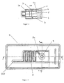
- Fig. 1 und Fig. 1a perspektivische Ansichten einer erfindungsgemäßen Tintenpatrone;
- Fig. 2 eine Draufsicht auf die Tintenpatrone der Fig. 1 und 1a;
- Fig. 3 einen Längsschnitt entlang der Ebene B-B von Fig. 2;
- Fig. 4 eine Draufsicht auf eine erste Ausführungsform des Deckels einer erfindungsgemäßen Patrone;
- Fig. 5 den Deckel von Fig. 4 im Querschnitt entlang der Ebene A-A von Fig. 4;
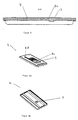
- Fig. 6a und 6b perspektivische Ansichten des Deckels der Fig. 4 und 5; und
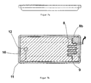
- Fig. 7 einen Deckel gemäß einer zweiten Ausführungsform der erfindungsgemäßen Patrone.
- In den Fig. 1a und 1b ist in perspektivischer Ansicht ein Gehäuse 1 einer erfindungsgemäßen Tintenpatrone zu sehen. Das Gehäuse weist einen Deckel 2 auf (in den Fig. 1a und 1b nicht sichtbar), welcher mit dem Unterteil des Gehäuses fest (beispielsweise durch Verschweißen) verbunden ist. Des weiteren weist das Gehäuse zwei Längswände 3 auf, zwischen deren oberen Enden 3a und deren unteren Enden 3b jeweils eine Verjüngung 3c vorhanden ist. Im gezeigten Fall ist das Gehäuse der Tintenpatrone nach unten hin verjüngt.
- Das Innere der Tintenpatrone ist durch Trennwände 4 untergliedert. Die Trennwände 4 begrenzen zum einen eine zentrale Tintenkammer 5, welche über die gesamte Länge eine einheitliche Dicke aufweist, sowie zwei Leerkammern 6; 7.
- Wie dies in der Draufsicht von Fig. 2 zu sehen ist, erstrecken sich die beiden Trennwände 4 durchgängig über die gesamte Länge des Gehäuses 1. Zwischen der Tintenkammer 5 und den beiden Leerkammern 6; 7 besteht keine Verbindung in den Trennwänden 4.
- In der Längsschnittansicht von Fig. 3 ist zu erkennen, daß die Trennwände 4 hier als Fortsatz des unteren Teils der Längswände 3 ausgebildet sind. Die Leerkammern 6; 7 erstrecken sich somit nicht bis zum Boden der Patrone. Es ist deutlich sichtbar, daß die Tintenkammer scheibenförmig ausgebildet ist, so daß ein aus einer einzelnen Schwammplatte ausgestanzter Schwamm ihren gesamten Innenraum füllen kann.
- Das beschriebene Gehäuse kann beispielsweise durch einen Deckel 2 verschlossen sein, wie er in den Fig. 4 bis Fig. 6 dargestellt ist. In der Draufsicht von Fig. 4 ist eine mäanderförmige Nut 8 zu erkennen, deren eines Ende 8a in eine Öffnung 9 ins Innere des Gehäuses mündet. Die Öffnung 9 ist hier zentral angeordnet, so daß sie direkt in die Tintenkammer 5 führt. Das zweite Ende 8b der mäanderförmigen Nut ist zu einem senkrechten Arm verlängert. Bei der Verwendung der Patrone ist zumindest der Bereich der Belüftungsöffnung 9 sowie der mäanderförmigen Nut 8 von einer Folie bedeckt, wobei eine Sollreißstelle so ausgebildet ist, daß beim Abreißen der Folie das Ende 8b freigelegt wird, so daß durch die Nut 8 und die Belüftungsöffnung 9 ein Luftaustausch mit der Umgebung stattfinden kann.
- In Fig. 5 ist ein Querschnitt durch den Deckel von Fig. 4 gezeigt, wobei deutlich die durchgehende Belüftungsöffnung 9 sowie die Nut bzw. Vertiefung 8 zu erkennen ist. In den Fig. 6 und 6a ist derselbe Deckel perspektivisch von oben bzw. perspektivisch von unten dargestellt.
- In Fig. 7 ist der Deckel einer zweiten Ausführungsform einer erfindungsgemäßen Tintenpatrone in Draufsicht gezeigt. Der untere Teil des Gehäuses dieser zweiten Ausführungsform entspricht dem in den Fig. 1 bis 3 dargestellten. Auch in diesem Deckel befindet sich auf der Oberseite eine mäanderförmige Nut 8, deren eines Ende 8a in eine Belüftungsöffnung 9 mündet. Die hier gezeigte Belüftungsöffnung 9 führt jedoch, anders als bei der vorher beschriebenen Ausführungsform, in eine der Leerkammern, im vorliegenden Fall in die rechte Leerkammer. Somit steht diese Leerkammer über die Nut mit der Umgebung in Verbindung. Von der Belüftungsöffnung beabstandet ist eine als Nut ausgebildete Verbindungsleitung 10 im Deckel 2 zu erkennen, welche die Tintenkammer mit der einen Leerkammer verbindet. Diese Verbindungsleitung 10 verläuft hier auf der Oberseite des Deckels, ebenso wie die mäanderförmige Nut 8. Das eine Ende der Nut mündet in eine Verbindungsöffnung 11, welche zur Leerkammer führt, und das andere Ende der Verbindungsleitung 10 mündet in eine Öffnung 12, welche zum Tintenbehälter führt. Der Deckel ist ganz oder nur im Bereich der gezeigten Nuten und Öffnungen von einer Siegelfolie bedeckt, die hier partiell durch schraffierte Linien angedeutet ist. An der strichlierten Linie in der linken oberen Ecke des Deckels kann eine Sollreißstelle ausgebildet sein, durch die das vordere Ende 8b der mäanderförmigen Nut freigelegt werden kann.
- Neben den gezeigten und beschriebenen Ausführungsformen sind zahlreiche Variationen möglich. So ist es beispielsweise denkbar, daß die Verbindungsleitung 10 nicht als Nut auf der Oberseite des Deckels, sondern als Nut auf der Unterseite des Deckels ausgebildet ist. Die Verbindungsöffnungen 11 und 12 können bei dieser Ausführungsform entfallen. Ein Vorteil dieser Ausführungsform liegt darin, daß weniger Siegelfolie verbraucht wird, da nur der Bereich der mäanderförmigen Nut 8 sowie der Belüftungsöffnung 9 von Folie bedeckt sein muß. Weiter ist es möglich, die nicht mit der Tintenkammer in Verbindung stehende Leerkammer mit einer Bohrung in der Außenwand zu versehen, um einen Ausgleich bei einem Abfall des Umgebungsdrucks, beispielsweise in großen Höhen, zu schaffen.
Claims (9)
- Tintenpatrone für einen Tintenstrahldrucker, aufweisend ein Gehäuse (1) mit Längswänden (3) und einem Deckel (2), wobei die Längswände (3) des Gehäuses (1) zwischen ihrem jeweiligen oberen Ende (3a) und ihrem jeweiligen unteren Ende (3b) eine Verjüngung (3c) aufweisen, so dass das Gehäuse (1) der Tintenpatrone verjüngt ist, dadurch gekennzeichnet, daß im Inneren der Tintenpatrone Trennwände (4) ausgebildet sind, die mindestens eine scheibenförmige Tintenkammer (5) zur Aufnahme eines porösen Materials begrenzen, und daß neben der mindestens einen Tintenkammer (5) mindestens eine Leerkammer (6; 7) vorhanden ist.
- Tintenpatrone nach Anspruch 1, dadurch gekennzeichnet, dass die mindestens eine Leerkammer (6; 7) nach einer Seite im wesentlichen von der Verjüngung (3c) begrenzt wird.
- Tintenpatrone nach einem der vorangehenden Ansprüche, dadurch gekennzeichnet, dass sich die mindestens eine Leerkammer (6; 7) nicht bis zu einem Boden der Tintenpatrone erstreckt.
- Tintenpatrone nach einem der vorangehenden Ansprüche, dadurch gekennzeichnet, daß auf der Oberseite des Deckels (2) eine mäanderförmige Nut (8) ausgebildet ist, deren eines Ende (8a) in eine Belüftungsöffnung (9) ins Innere des Gehäuses (1) mündet.
- Tintenpatrone nach Anspruch 4, dadurch gekennzeichnet, daß die Belüftungsöffnung (9) in die Tintenkammer (5) mündet, wobei die Tintenkammer (5) hermetisch gegen die mindestens eine Leerkammer (6; 7) abgedichtet ist.
- Tintenpatrone nach Anspruch 4, dadurch gekennzeichnet, daß die Belüftungsöffnung (9) in eine der Leerkammem (6) mündet, wobei eine Verbindungsleitung (10) zwischen dieser Leerkammer (6) und der Tintenkammer (5) vorhanden ist.
- Tintenpatrone nach Anspruch 6, dadurch gekennzeichnet, daß die Verbindungsleitung (10) als eine Nut im Deckel (2) ausgebildet ist.
- Tintenpatrone nach Anspruch 7, dadurch gekennzeichnet, daß die die Verbindungsleitung (10) bildende Nut an der Oberseite des Deckels (2) ausgebildet und von einer Folie bedeckt ist.
- Tintenpatrone nach einem der Ansprüche 6 bis 8, dadurch gekennzeichnet, daß an der Leerkammer (6) im Bereich der Verbindungsöffnung (11) zur Tintenkammer ein saugfähiges Material angebracht ist.
Applications Claiming Priority (2)
| Application Number | Priority Date | Filing Date | Title |
|---|---|---|---|
| DE10133465A DE10133465B4 (de) | 2001-07-10 | 2001-07-10 | Tintenpatrone mit Leerkammer |
| DE10133465 | 2001-07-10 |
Publications (3)
| Publication Number | Publication Date |
|---|---|
| EP1275509A2 EP1275509A2 (de) | 2003-01-15 |
| EP1275509A3 EP1275509A3 (de) | 2003-08-20 |
| EP1275509B1 true EP1275509B1 (de) | 2006-10-11 |
Family
ID=7691264
Family Applications (1)
| Application Number | Title | Priority Date | Filing Date |
|---|---|---|---|
| EP02013465A Expired - Lifetime EP1275509B1 (de) | 2001-07-10 | 2002-06-14 | Tintenpatrone mit Leerkammer |
Country Status (3)
| Country | Link |
|---|---|
| EP (1) | EP1275509B1 (de) |
| AT (1) | ATE342168T1 (de) |
| DE (2) | DE10133465B4 (de) |
Family Cites Families (9)
| Publication number | Priority date | Publication date | Assignee | Title |
|---|---|---|---|---|
| JP3513979B2 (ja) * | 1994-09-16 | 2004-03-31 | セイコーエプソン株式会社 | インクジェットプリンタ用インクカートリッジ |
| US6247803B1 (en) * | 1983-10-13 | 2001-06-19 | Seiko Epson Corporation | Ink jet recording apparatus and method for replenishing ink in the tank cartridge |
| EP0424133B1 (de) * | 1989-10-20 | 1995-03-22 | Canon Kabushiki Kaisha | Kassette mit Tintenvorratsbehälter auf einem Farbstrahlgerät aufstellbar |
| US6007191A (en) * | 1993-08-19 | 1999-12-28 | Fuji Xerox Co., Ltd. | Ink supply unit |
| DE69430345T2 (de) * | 1993-08-23 | 2002-10-10 | Canon K.K., Tokio/Tokyo | Auswechselbare Tintenpatrone |
| US6168266B1 (en) * | 1995-09-29 | 2001-01-02 | Canon Kabushiki Kaisha | Ink tank cartridge, a manufacturing method thereof and a packaging structure of the ink tank cartridge |
| JP3750138B2 (ja) * | 1996-02-21 | 2006-03-01 | セイコーエプソン株式会社 | インクカートリッヂ |
| JP3287791B2 (ja) * | 1997-07-30 | 2002-06-04 | キヤノン株式会社 | 液体収容室を有する液体収容容器への液体充填方法及び液体充填装置 |
| EP1300248B1 (de) * | 1998-03-30 | 2008-10-22 | Brother Kogyo Kabushiki Kaisha | Tintenpatrone und Verfahren zur Detektion der restlichen Tintenmenge |
-
2001
- 2001-07-10 DE DE10133465A patent/DE10133465B4/de not_active Expired - Fee Related
-
2002
- 2002-06-14 DE DE50208383T patent/DE50208383D1/de not_active Expired - Lifetime
- 2002-06-14 AT AT02013465T patent/ATE342168T1/de not_active IP Right Cessation
- 2002-06-14 EP EP02013465A patent/EP1275509B1/de not_active Expired - Lifetime
Also Published As
| Publication number | Publication date |
|---|---|
| DE10133465B4 (de) | 2006-10-05 |
| DE10133465A1 (de) | 2003-01-30 |
| EP1275509A3 (de) | 2003-08-20 |
| EP1275509A2 (de) | 2003-01-15 |
| ATE342168T1 (de) | 2006-11-15 |
| DE50208383D1 (de) | 2006-11-23 |
Similar Documents
| Publication | Publication Date | Title |
|---|---|---|
| DE4328001C2 (de) | Tintenbehälter | |
| DE69332695T2 (de) | Kartonverpackung mit Innenbeutel und Ausgussstülle | |
| DE69417353T2 (de) | Tintenbehälter, Ein-Ausbauverfahren und Gerät zur Anwendung | |
| DE69324146T2 (de) | Klappschachtel mit herausspringendem gutschein | |
| DE69333791T2 (de) | Tintenstrahlpatrone, Tintenstrahlkopf und Drucker | |
| EP0801010B2 (de) | Klappschachtel, insbesondere für Zigaretten | |
| EP3215441A1 (de) | Transportbehälter | |
| DE1529970B2 (de) | Verfahren zur herstellung eines boden und seitenwaende auf weisenden behaelters | |
| DE69411080T2 (de) | Verfahren und Vorrichtung zur Herstellung einer mit körnigem Material gefüllten Vakkuumverpackung | |
| WO2001012527A1 (de) | Klappschachtel für zigaretten | |
| EP1880948A2 (de) | Transportkasten und Spritzvorrichtung für einen Transportkasten | |
| DE2551427C2 (de) | Schachtel mit Klappdeckel | |
| DE2833494C2 (de) | Klappschachtel, insbesondere für Zigaretten | |
| DE2428355C3 (de) | Verfahren zum Füllen und Verschließen von Verpackungsbehältern und nach dem Verfahren hergestellter Behälter | |
| EP1007446A1 (de) | Klappschachtel für zigaretten | |
| DE2844444C2 (de) | Verpackung, insbesondere quaderförmige Zigarettenpackung, und Verfahren zur Herstellung von Zuschnitten für diese Verpackung | |
| DE2231262A1 (de) | Verpackungsbehaelter und verfahren zu seiner herstellung | |
| DE19729313A1 (de) | Tür | |
| DE10133465B4 (de) | Tintenpatrone mit Leerkammer | |
| DE4307818A1 (de) | Wandelement | |
| EP0160978A2 (de) | Verschlussmembran für Behälter mit gas-entwickelndem Füllgut | |
| EP2214908B1 (de) | Tintenpatrone, insbesondere für einen tintenstrahldrucker | |
| EP0653363B1 (de) | Zigaretten-Packung mit Deckel | |
| EP3072704A1 (de) | Auftragstasche | |
| EP0628484B1 (de) | Verpackungseinheit für mit Pipettenspitzen bestückten, zum Einsatz in autoklavierbaren Behältern bestimmten, einen Randflansch aufweisenden Lochplatten |
Legal Events
| Date | Code | Title | Description |
|---|---|---|---|
| PUAI | Public reference made under article 153(3) epc to a published international application that has entered the european phase |
Free format text: ORIGINAL CODE: 0009012 |
|
| AK | Designated contracting states |
Kind code of ref document: A2 Designated state(s): AT BE CH CY DE DK ES FI FR GB GR IE IT LI LU MC NL PT SE TR |
|
| AX | Request for extension of the european patent |
Free format text: AL;LT;LV;MK;RO;SI |
|
| PUAL | Search report despatched |
Free format text: ORIGINAL CODE: 0009013 |
|
| AK | Designated contracting states |
Designated state(s): AT BE CH CY DE DK ES FI FR GB GR IE IT LI LU MC NL PT SE TR |
|
| AX | Request for extension of the european patent |
Extension state: AL LT LV MK RO SI |
|
| 17P | Request for examination filed |
Effective date: 20030929 |
|
| 17Q | First examination report despatched |
Effective date: 20040212 |
|
| AKX | Designation fees paid |
Designated state(s): CH DE FR GB IT LI |
|
| RBV | Designated contracting states (corrected) |
Designated state(s): AT BE CH CY DE DK ES FI FR GB GR IE IT LI LU MC NL PT SE TR |
|
| GRAP | Despatch of communication of intention to grant a patent |
Free format text: ORIGINAL CODE: EPIDOSNIGR1 |
|
| GRAS | Grant fee paid |
Free format text: ORIGINAL CODE: EPIDOSNIGR3 |
|
| GRAA | (expected) grant |
Free format text: ORIGINAL CODE: 0009210 |
|
| AK | Designated contracting states |
Kind code of ref document: B1 Designated state(s): AT BE CH CY DE DK ES FI FR GB GR IE IT LI LU MC NL PT SE TR |
|
| PG25 | Lapsed in a contracting state [announced via postgrant information from national office to epo] |
Ref country code: NL Free format text: LAPSE BECAUSE OF FAILURE TO SUBMIT A TRANSLATION OF THE DESCRIPTION OR TO PAY THE FEE WITHIN THE PRESCRIBED TIME-LIMIT Effective date: 20061011 Ref country code: FI Free format text: LAPSE BECAUSE OF FAILURE TO SUBMIT A TRANSLATION OF THE DESCRIPTION OR TO PAY THE FEE WITHIN THE PRESCRIBED TIME-LIMIT Effective date: 20061011 Ref country code: IE Free format text: LAPSE BECAUSE OF FAILURE TO SUBMIT A TRANSLATION OF THE DESCRIPTION OR TO PAY THE FEE WITHIN THE PRESCRIBED TIME-LIMIT Effective date: 20061011 |
|
| REG | Reference to a national code |
Ref country code: GB Ref legal event code: FG4D Free format text: NOT ENGLISH |
|
| REG | Reference to a national code |
Ref country code: CH Ref legal event code: EP |
|
| REG | Reference to a national code |
Ref country code: IE Ref legal event code: FG4D Free format text: LANGUAGE OF EP DOCUMENT: GERMAN |
|
| REF | Corresponds to: |
Ref document number: 50208383 Country of ref document: DE Date of ref document: 20061123 Kind code of ref document: P |
|
| PG25 | Lapsed in a contracting state [announced via postgrant information from national office to epo] |
Ref country code: SE Free format text: LAPSE BECAUSE OF FAILURE TO SUBMIT A TRANSLATION OF THE DESCRIPTION OR TO PAY THE FEE WITHIN THE PRESCRIBED TIME-LIMIT Effective date: 20070111 Ref country code: DK Free format text: LAPSE BECAUSE OF FAILURE TO SUBMIT A TRANSLATION OF THE DESCRIPTION OR TO PAY THE FEE WITHIN THE PRESCRIBED TIME-LIMIT Effective date: 20070111 |
|
| PG25 | Lapsed in a contracting state [announced via postgrant information from national office to epo] |
Ref country code: ES Free format text: LAPSE BECAUSE OF FAILURE TO SUBMIT A TRANSLATION OF THE DESCRIPTION OR TO PAY THE FEE WITHIN THE PRESCRIBED TIME-LIMIT Effective date: 20070122 |
|
| PG25 | Lapsed in a contracting state [announced via postgrant information from national office to epo] |
Ref country code: PT Free format text: LAPSE BECAUSE OF FAILURE TO SUBMIT A TRANSLATION OF THE DESCRIPTION OR TO PAY THE FEE WITHIN THE PRESCRIBED TIME-LIMIT Effective date: 20070319 |
|
| NLV1 | Nl: lapsed or annulled due to failure to fulfill the requirements of art. 29p and 29m of the patents act | ||
| ET | Fr: translation filed | ||
| GBV | Gb: ep patent (uk) treated as always having been void in accordance with gb section 77(7)/1977 [no translation filed] |
Effective date: 20061011 |
|
| REG | Reference to a national code |
Ref country code: IE Ref legal event code: FD4D |
|
| PLBE | No opposition filed within time limit |
Free format text: ORIGINAL CODE: 0009261 |
|
| STAA | Information on the status of an ep patent application or granted ep patent |
Free format text: STATUS: NO OPPOSITION FILED WITHIN TIME LIMIT |
|
| 26N | No opposition filed |
Effective date: 20070712 |
|
| PG25 | Lapsed in a contracting state [announced via postgrant information from national office to epo] |
Ref country code: GB Free format text: LAPSE BECAUSE OF FAILURE TO SUBMIT A TRANSLATION OF THE DESCRIPTION OR TO PAY THE FEE WITHIN THE PRESCRIBED TIME-LIMIT Effective date: 20061011 |
|
| BERE | Be: lapsed |
Owner name: PELIKAN HARDCOPY PRODUCTION A.G. Effective date: 20070630 |
|
| PG25 | Lapsed in a contracting state [announced via postgrant information from national office to epo] |
Ref country code: MC Free format text: LAPSE BECAUSE OF NON-PAYMENT OF DUE FEES Effective date: 20070630 |
|
| PG25 | Lapsed in a contracting state [announced via postgrant information from national office to epo] |
Ref country code: BE Free format text: LAPSE BECAUSE OF NON-PAYMENT OF DUE FEES Effective date: 20070630 |
|
| PG25 | Lapsed in a contracting state [announced via postgrant information from national office to epo] |
Ref country code: GR Free format text: LAPSE BECAUSE OF FAILURE TO SUBMIT A TRANSLATION OF THE DESCRIPTION OR TO PAY THE FEE WITHIN THE PRESCRIBED TIME-LIMIT Effective date: 20070112 |
|
| PG25 | Lapsed in a contracting state [announced via postgrant information from national office to epo] |
Ref country code: AT Free format text: LAPSE BECAUSE OF NON-PAYMENT OF DUE FEES Effective date: 20070614 |
|
| REG | Reference to a national code |
Ref country code: CH Ref legal event code: PCOW Free format text: PELIKAN HARDCOPY PRODUCTION AG;GEWERBESTRASSE 9;8132 EGG BEI ZUERICH (CH) |
|
| PG25 | Lapsed in a contracting state [announced via postgrant information from national office to epo] |
Ref country code: LU Free format text: LAPSE BECAUSE OF NON-PAYMENT OF DUE FEES Effective date: 20070614 Ref country code: CY Free format text: LAPSE BECAUSE OF FAILURE TO SUBMIT A TRANSLATION OF THE DESCRIPTION OR TO PAY THE FEE WITHIN THE PRESCRIBED TIME-LIMIT Effective date: 20061011 |
|
| PG25 | Lapsed in a contracting state [announced via postgrant information from national office to epo] |
Ref country code: TR Free format text: LAPSE BECAUSE OF FAILURE TO SUBMIT A TRANSLATION OF THE DESCRIPTION OR TO PAY THE FEE WITHIN THE PRESCRIBED TIME-LIMIT Effective date: 20061011 |
|
| PGFP | Annual fee paid to national office [announced via postgrant information from national office to epo] |
Ref country code: CH Payment date: 20090630 Year of fee payment: 8 Ref country code: FR Payment date: 20090630 Year of fee payment: 8 |
|
| PGFP | Annual fee paid to national office [announced via postgrant information from national office to epo] |
Ref country code: IT Payment date: 20090630 Year of fee payment: 8 |
|
| PGFP | Annual fee paid to national office [announced via postgrant information from national office to epo] |
Ref country code: DE Payment date: 20100827 Year of fee payment: 9 |
|
| REG | Reference to a national code |
Ref country code: CH Ref legal event code: PL |
|
| REG | Reference to a national code |
Ref country code: FR Ref legal event code: ST Effective date: 20110228 |
|
| PG25 | Lapsed in a contracting state [announced via postgrant information from national office to epo] |
Ref country code: IT Free format text: LAPSE BECAUSE OF NON-PAYMENT OF DUE FEES Effective date: 20100614 |
|
| PG25 | Lapsed in a contracting state [announced via postgrant information from national office to epo] |
Ref country code: LI Free format text: LAPSE BECAUSE OF NON-PAYMENT OF DUE FEES Effective date: 20100630 Ref country code: CH Free format text: LAPSE BECAUSE OF NON-PAYMENT OF DUE FEES Effective date: 20100630 |
|
| PG25 | Lapsed in a contracting state [announced via postgrant information from national office to epo] |
Ref country code: FR Free format text: LAPSE BECAUSE OF NON-PAYMENT OF DUE FEES Effective date: 20100630 |
|
| REG | Reference to a national code |
Ref country code: DE Ref legal event code: R119 Ref document number: 50208383 Country of ref document: DE Effective date: 20120103 |
|
| PG25 | Lapsed in a contracting state [announced via postgrant information from national office to epo] |
Ref country code: DE Free format text: LAPSE BECAUSE OF NON-PAYMENT OF DUE FEES Effective date: 20120103 |