EP1275332B1 - Kochelement für Kochraum mit Dampf - Google Patents
Kochelement für Kochraum mit Dampf Download PDFInfo
- Publication number
- EP1275332B1 EP1275332B1 EP02356121A EP02356121A EP1275332B1 EP 1275332 B1 EP1275332 B1 EP 1275332B1 EP 02356121 A EP02356121 A EP 02356121A EP 02356121 A EP02356121 A EP 02356121A EP 1275332 B1 EP1275332 B1 EP 1275332B1
- Authority
- EP
- European Patent Office
- Prior art keywords
- side wall
- cooking
- cooking element
- element according
- annular side
- Prior art date
- Legal status (The legal status is an assumption and is not a legal conclusion. Google has not performed a legal analysis and makes no representation as to the accuracy of the status listed.)
- Expired - Lifetime
Links
Images


Classifications
-
- A—HUMAN NECESSITIES
- A47—FURNITURE; DOMESTIC ARTICLES OR APPLIANCES; COFFEE MILLS; SPICE MILLS; SUCTION CLEANERS IN GENERAL
- A47J—KITCHEN EQUIPMENT; COFFEE MILLS; SPICE MILLS; APPARATUS FOR MAKING BEVERAGES
- A47J27/00—Cooking-vessels
- A47J27/04—Cooking-vessels for cooking food in steam; Devices for extracting fruit juice by means of steam ; Vacuum cooking vessels
- A47J27/05—Tier steam-cookers, i.e. with steam-tight joints between cooking-vessels stacked while in use
-
- A—HUMAN NECESSITIES
- A47—FURNITURE; DOMESTIC ARTICLES OR APPLIANCES; COFFEE MILLS; SPICE MILLS; SUCTION CLEANERS IN GENERAL
- A47J—KITCHEN EQUIPMENT; COFFEE MILLS; SPICE MILLS; APPARATUS FOR MAKING BEVERAGES
- A47J37/00—Baking; Roasting; Grilling; Frying
- A47J37/01—Vessels uniquely adapted for baking
Definitions
- the present invention relates to the general technical field of apparatus or utensils intended for steam cooking.
- appliances or utensils intended for cooking in the steam comprise a cooking chamber associated with a water tank.
- the water in the tank is heated to produce steam for cooking food contained in the cooking chamber.
- Electrical appliances steam cooking comprise an electric heating means for the steam production from the reservoir water.
- Such devices generally have a heating base on which one or several cooking elements forming the cooking chamber.
- WO 00/30511 discloses a cooking element composed of a wall annular side and removable perforated bottom.
- the annular side walls are stackable.
- a cooking chamber can thus comprise several superimposed cooking elements, for simultaneously cooking food on different superimposed layers, or several annular side walls associated with a single bottom, so as to have a larger cooking volume, to cook for example a chicken.
- stackable and interchangeable cooking elements are very user-friendly, but have the disadvantage of remaining bulky in all circumstances.
- Stackable cooking elements Nesting areas reduce the space required for storage but ask for a superposition of the cooking elements according to an order specific.
- the volume of the cooking chamber can only be modulated in the sense of height.
- the object of the present invention is to improve the possibilities of using a cooking element for steam cooking chamber.
- An additional object of the present invention is to propose an element of cooking for a steam cooking chamber, which allows to limit the space required for storage, and whose construction allows to consider if desired the superposition interchangeably with a other cooking element.
- Another additional object of the present invention is to propose an element cooking chamber for steam cooking chamber, which allows to modulate the cooking volume.
- a cooking element for cooking chamber with an annular side wall associated where appropriate with one or more removable perforated bottoms, because the annular side wall has at least two movable cross-sections with respect to the other by sliding and / or by elastic deformation of the side wall ring and / or joint.
- cross section of the side wall ring means a section extending over the entire height of the wall lateral section, and not a section extending along the entire perimeter of said annular side wall. This provision reduces or to increase the length of the perimeter of the annular side wall, or to modify the geometry of the annular side wall.
- the element of baking according to the invention can, for storage, be particularly disposed to inside or around another cooking element, this other element of baking that can be stackable and interchangeable with the element of cooking according to the invention.
- the congestion gain in height is very important, while the additional side volume needed for storage is limited or even nil.
- the association of the annular side wall with Removable funds of different sizes can be used to modulate the volume of the cooking chamber in the direction of the length and / or the width, and not in the sense of height.
- the annular side wall comprises a portion flexible longitudinal arrangement, this provision making it possible to simplify the the cooking element while facilitating the holding of the cooking element during the cooking.
- the flexible longitudinal portion of the side wall extends over at least part of the perimeter of the side wall, all the way up the side wall.
- the flexible longitudinal portion extends over more than half of the circumference of the annular side wall. This provision allows the use of stiffer materials for the annular sidewall.
- the provision has the advantage of allowing several positions of use for cooking. Several removable funds adapted to the configuration of the different cooking positions of the side wall can then be expected. In addition, the thickness of funds can be very small, these are not bulky.
- one of said cross-sections forms a chamber in which slides the other of said sections cross. This arrangement makes it easier to guide.
- the chamber has an upper opening as well than a lower opening.
- the chamber can thus form a conduit for the steam passage.
- the chamber then extends over the entire height of the annular side wall.
- said cross sections come from at least two pieces different. These parts can be dismountably assembled or no.
- the annular lateral wall presents an area made of flexible and / or elastically deformable material, extending over the height of the annular side wall, at least two of the transverse sections being disposed on either side of said zone.
- the made of flexible and / or elastically deformable material in particular to be associated with a flexible longitudinal portion, or with a portion longitudinal joint of the annular side wall.
- At least two of the sections transverse members have at least one articulation relative to one another.
- the annular side wall may for example have two sections transverse, each having two articulations with the other section.
- the annular side wall is then closed.
- the annular side wall can also have two cross-sections each with a single articulation with the other section.
- the annular side wall is then open, each of the sections having a free lateral edge.
- the at least one of the joints is formed by a thinned area of the side wall.
- the side wall can example be obtained by molding a piece of polypropylene, which allows to realize a very economical cooking element.
- the at least one of the articulations has a convex portion rotating in a concave portion.
- Rooms forming the side wall can also be obtained by molding.
- the at least one of the articulations has an axis assembling said cross sections. If desired, the axis can be dismountable.
- Joints do not necessarily pivot around a direction parallel to the side wall but may for example pivot with respect to a radial direction relative to the side wall.
- FIG 1 shows a first embodiment of the invention.
- Two baking containers 1, 2 superimposed form part of an enclosure of steam cooking.
- the two containers 1, 2 are interchangeable.
- Each cooking vessel has an annular side wall 3, 4 provided with of gripping members 5, 6.
- An annular flange 7, 8 formed on the face inside of the annular side wall 3, 4 forms a support for a bottom perforated removable 9, 10.
- Each annular side wall 3, 4 forms a broken ring and has two transverse sections 11, 12 sliding longitudinally with respect to the other thanks to an elastic deformation of the annular wall.
- One of 12 transverse sections forms a chamber 13 in which slides the other cross section 11.
- Each chamber 13 has an opening upper 14 and a lower opening formed behind a lower edge 15.
- the side walls 3, 4 are slightly conical, so that the rim 15 of the upper container 2 can engage in the opening 14 of the lower container 1.
- the two chambers 13 then form a conduit allowing for example the passage of steam.
- the cross section 11 has an end engaging in the chamber 13 of the cooking element.
- Cross section 11 belongs to a piece 16 forming more than half the circumference of the element of cooking.
- the free end of the piece 16 opposite to the cross section 11 is assembled with another room 17 in which the chamber is arranged 13.
- the assembly of parts 16 and 17 is preferably not removable.
- Each annular side wall 3, 4 forms a cooking element for a steam cooking chamber.
- Each of the pieces 16 forms a portion flexible longitudinal 18, 19 of the side wall 3, 4.
- Several side walls 3, 4 superimposed can be associated with a single perforated bottom to form a cooking chamber of a larger volume.
- the user removes the removable bottom 9 or 10 of one of the side walls 3 or 4, and inserts the cross section 11 in the chamber 13 thanks to the flexibility of the portion longitudinal 18 or 19, thereby reducing the perimeter of said side wall.
- the sidewall whose perimeter is reduced can take place inside from the other side wall. Several side walls can thus be interlocked.
- the user can also associate with the side walls 3 or 4 funds movable to a size smaller than the funds 9 or 10, in order to obtain an element of cooking a smaller perimeter.
- FIG. 2 shows a variant of the exemplary embodiment shown in FIG. 1.
- the cooking element has an annular side wall 20 having a cross section 21 sliding in a cross section 22 forming a trigger.
- the inner face of the annular side wall 20 also comprises supports 23 provided for receiving a removable bottom perforated.
- the cross sections 21, 22 are joined by a portion longitudinal flexible 29 to form the annular side wall 20.
- the perimeter of the lateral wall in position may be smaller than the perimeter of the side wall in position storage.
- the side wall of the cooking element can then be arranged around another utensil, such as for example an element of cooking with removable bottom as described in WO 00/30511, or a non-removable bottom cooking element, or a heating base described in WO 00/30510.
- two sliding zones such as the chamber 13 or the trigger section 22, for example diametrically opposite, facilitate the extension or contraction of the perimeter of the side wall.
- the sliding zones are then formed in straight portions of the side wall.
- FIG. 3 presents a third exemplary embodiment in which the element baking comprises an annular side wall 30 having a zone 33, made of flexible material, extending over the height of the annular wall 30.
- the zone 33 may be formed by a piece 34 fixed to the transverse sections 31, 32.
- the cross sections 31, 32 belong to a portion flexible longitudinal tube 39 having in the lower part of the inner face a rib 35 provided to support a removable perforated bottom. So advantageously, the flexible longitudinal portion 39 tends to reduce the sections transverse 31, 32 in contiguous position.
- the zone 33 may be made of elastic material deformable, for example flexible material and / or extensible material.
- the cross sections 31, 32 may be connected by a flexible or articulated longitudinal portion of the annular wall 30.
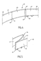
- FIG. 4 presents a fourth exemplary embodiment in which the element of cooking comprises an annular side wall 40 presenting a first thinned zone 44 formed on the outer face and a second thinned zone 45 formed on the inner face.
- the two thinned zones 44, 45 extend over the entire height of the side wall 40.
- the side wall 40 may in particular be made of polypropylene.
- the two thinned areas 44, 45 thus form two joints 46, 47.
- the Annular wall 40 has an amount 43 framed by the joints 46, 47.
- the amount 43 is likely to pivot relative to the cross sections 41, 42 adjacent to the joints 46, 47, as shown in FIG. cross sections 41, 42 are connected by a flexible longitudinal portion 49 having in the lower part of the inner face of the lugs 48 provided to support a removable perforated bottom.
- the embodiment shown in FIG. 6 differs from the exemplary embodiment previous in that the joints 56, 57 are formed by the edges side of the upright 53 pivoting in the lateral edges of the sections 51, 52.
- the lateral edges of the upright 53 form the parts convexes 54 of the articulations 56, 57 and the lateral edges of the sections transverse 51, 52 form the concave portions 55 of the joints 56, 57.
- the cross sections 51, 52 are joined by a longitudinal portion flexible 59 having in the lower part of the inner face of the lugs 58 provided to support a removable perforated bottom.
- FIG. 7 differs from the exemplary embodiment previous in that the joints 66, 67 are formed by hinges.
- An axis 64 shown partly in FIG. 7, makes it possible to cross section 61 and the amount 63, allowing their rotation.
- Another axis 65 secures the cross section 62 and the amount 63, in allowing their rotation.
- the cross sections 61, 62 are joined by a flexible longitudinal portion 69 having in the lower part of the face internal lugs 68 provided to support a removable perforated bottom.
- the annular side wall may comprise two parts joined together by a joint, one of the side edges of each piece belonging to the articulation, the other lateral edge of each piece which can be brought together or away from the other side edge of the other piece by pivoting parts.
- the annular side wall then does not necessarily have a portion longitudinal flexible.
- the annular side wall can have a plurality of flexible longitudinal portions.
- Removable funds may include one or more rooms.
- a cooking element according to the invention can be associated by superposition with another element of baking according to the invention, and / or a cooking element in which the geometry of the annular side wall can not be modified, for example to a cooking vessel comprising a perforated bottom integral with the wall lateral annular.
Landscapes
- Engineering & Computer Science (AREA)
- Food Science & Technology (AREA)
- Cookers (AREA)
Claims (12)
- Garelement für einen Raum zum Garen mit Dampf, mit einer ringförmigen Seitenwand (3; 4; 20; 30; 40; 50; 60), die gegebenenfalls einem oder mehreren abnehmbaren, durchlöcherten Böden (9; 10) zugeordnet ist, dadurch gekennzeichnet, dass die ringförmige Seitenwand (3; 4; 20; 30; 40; 50; 60) mindestens zwei Querschnitte (11, 12; 21, 22; 31, 32; 41, 42; 51, 52; 61, 62) aufweist, die durch Gleiten und/oder durch elastische Verformung der ringförmigen Seitenwand und/oder durch Anlenkung zueinander beweglich sind.
- Garelement nach Anspruch 1, dadurch gekennzeichnet, dass die ringförmige Seitenwand (3; 4; 20; 30; 40; 50; 60) einen nachgiebigen Längsabschnitt (18; 19; 29; 39; 49; 59; 69) aufweist.
- Garelement nach Anspruch 2, dadurch gekennzeichnet, dass sich der nachgiebige Längsabschnitt (18; 19; 29; 39; 49; 59; 69) über mehr als die Hälfte des Umfangs der ringförmigen Seitenwand (3; 4; 20; 30; 40; 50; 60) erstreckt.
- Garelement nach einem der Ansprüche 1 bis 3, dadurch gekennzeichnet, dass mindestens zwei (11, 12; 21, 22) der Querschnitte der Länge nach zueinander gleiten, wobei einer (11; 21) dieser Querschnitte bezüglich des anderen (12; 22) gleitet.
- Garelement nach Anspruch 4, dadurch gekennzeichnet, dass einer (12; 22) der Querschnitte eine Kammer (13; 23) bildet, in welcher der andere (11; 21) der Querschnitte gleitet.
- Garelement nach Anspruch 5, dadurch gekennzeichnet, dass die Kammer (13) eine obere Öffnung (14) sowie eine untere Öffnung (15) aufweist.
- Garelement nach einem der Ansprüche 4 bis 6, dadurch gekennzeichnet, dass die Querschnitte (11, 12) aus mindestens zwei verschiedenen Teilen (16, 17) hervorgehen.
- Garelement nach einem der Ansprüche 1 bis 3, dadurch gekennzeichnet, dass die ringförmige Seitenwand (30) einen Bereich (33) aufweist, der aus flexiblem und/oder elastisch verformbarem Material hergestellt ist und sich über die Höhe der ringförmigen Seitenwand (30) erstreckt, wobei mindestens zwei (31, 32) der Querschnitte auf der einen und der anderen Seite des Bereichs (33) angeordnet sind.
- Garelement nach einem der Ansprüche 1 bis 3, dadurch gekennzeichnet, dass mindestens zwei (41, 43; 42, 43; 51, 53; 52, 53; 61, 63; 62, 63) der Querschnitte zueinander mindestens ein Gelenk (46; 47; 56; 57; 66; 67) aufweisen.
- Garelement nach Anspruch 9, dadurch gekennzeichnet, dass das Gelenk oder mindestens eines der Gelenke (46; 47) durch einen verdünnten Bereich (43; 44) der Seitenwand (40) gebildet ist.
- Garelement nach Anspruch 9, dadurch gekennzeichnet, dass das Gelenk oder mindestens eines der Gelenke (56; 57) einen konvexen Abschnitt (54) aufweist, der in einem konkaven Abschnitt (55) dreht.
- Garelement nach Anspruch 9, dadurch gekennzeichnet, dass das Gelenk oder mindestens eines der Gelenke (66; 67) einen Zapfen (64; 65) aufweist, der die Querschnitte (61, 63; 62, 63) zusammenfügt.
Applications Claiming Priority (2)
| Application Number | Priority Date | Filing Date | Title |
|---|---|---|---|
| FR0109404A FR2827144B1 (fr) | 2001-07-13 | 2001-07-13 | Element de cuisson pour enceinte de cuisson a la vapeur |
| FR0109404 | 2001-07-13 |
Publications (2)
| Publication Number | Publication Date |
|---|---|
| EP1275332A1 EP1275332A1 (de) | 2003-01-15 |
| EP1275332B1 true EP1275332B1 (de) | 2005-08-10 |
Family
ID=8865511
Family Applications (1)
| Application Number | Title | Priority Date | Filing Date |
|---|---|---|---|
| EP02356121A Expired - Lifetime EP1275332B1 (de) | 2001-07-13 | 2002-07-02 | Kochelement für Kochraum mit Dampf |
Country Status (4)
| Country | Link |
|---|---|
| EP (1) | EP1275332B1 (de) |
| AT (1) | ATE301412T1 (de) |
| DE (1) | DE60205434T2 (de) |
| FR (1) | FR2827144B1 (de) |
Families Citing this family (3)
| Publication number | Priority date | Publication date | Assignee | Title |
|---|---|---|---|---|
| FR2913582A1 (fr) * | 2007-03-15 | 2008-09-19 | Innocent Lalague | Chauffe biberons et petit pot portable et pliable a batterie rechangeable. |
| CN106213985A (zh) * | 2016-08-30 | 2016-12-14 | 浙江尚厨炊具有限公司 | 一种压力锅 |
| CN106963236B (zh) * | 2017-05-18 | 2019-01-25 | 宁波金涛电子有限公司 | 电蒸锅 |
Family Cites Families (5)
| Publication number | Priority date | Publication date | Assignee | Title |
|---|---|---|---|---|
| BE377877A (de) * | ||||
| US2667117A (en) * | 1950-06-02 | 1954-01-26 | Millard | Adjustable colander for cooking and serving vegetables and the like |
| GB9116669D0 (en) * | 1991-08-01 | 1991-09-18 | Sentech Enterprise Limited | Vegetable steamer arrangement |
| FR2786083B1 (fr) | 1998-11-19 | 2001-01-05 | Seb Sa | Cuiseur a vapeur a remplissage lateral d'eau |
| FR2786082B1 (fr) | 1998-11-19 | 2000-12-29 | Seb Sa | Recipient de cuisson pour cuiseur a la vapeur |
-
2001
- 2001-07-13 FR FR0109404A patent/FR2827144B1/fr not_active Expired - Fee Related
-
2002
- 2002-07-02 AT AT02356121T patent/ATE301412T1/de not_active IP Right Cessation
- 2002-07-02 DE DE60205434T patent/DE60205434T2/de not_active Expired - Fee Related
- 2002-07-02 EP EP02356121A patent/EP1275332B1/de not_active Expired - Lifetime
Also Published As
| Publication number | Publication date |
|---|---|
| ATE301412T1 (de) | 2005-08-15 |
| EP1275332A1 (de) | 2003-01-15 |
| FR2827144A1 (fr) | 2003-01-17 |
| DE60205434T2 (de) | 2006-05-24 |
| FR2827144B1 (fr) | 2003-11-28 |
| DE60205434D1 (de) | 2005-09-15 |
Similar Documents
| Publication | Publication Date | Title |
|---|---|---|
| EP3072423B1 (de) | Schnellkochtopf mit bajonettverschluss, und entsprechendes herstellungsverfahren | |
| BE1006495A3 (fr) | Assemblage de fermeture pour recipient. | |
| EP1130988B1 (de) | Kochgefäss für ein dampfkochgerät | |
| BE1008061A3 (fr) | Dispositif de fermeture pour recipient. | |
| EP3122212B1 (de) | Druckkochtopf mit bajonetthalterung und zugehöriges herstellungsverfahren | |
| EP1275332B1 (de) | Kochelement für Kochraum mit Dampf | |
| CH617335A5 (en) | Set of serving dishes | |
| FR2854134A3 (fr) | Recipient muni d'un couvercle,en particulier pour aliments. | |
| EP2978347B1 (de) | Ofen | |
| EP3262996B1 (de) | Deckel eines kochbehälters mit ausgiesselement | |
| FR2622872A1 (fr) | Recipient metallique perfectionne muni d'un couvercle hermetique | |
| CH437014A (fr) | Récipient et son support | |
| EP2996525A1 (de) | Kochelement mit abnehmbarem boden für dampfgarer | |
| CA3075961A1 (fr) | Stem pour valve a deux voies | |
| FR2724304A1 (fr) | Systeme de fermeture d'un autocuiseur a vapeur | |
| EP1039821A1 (de) | Druckkochgerät mit bajonett-verschluss und giesstülle | |
| FR3095934A1 (fr) | récipients à doubles parois | |
| EP3738486A1 (de) | Elastischer ring für behälter mit doppelwand | |
| FR2814719A1 (fr) | Couvercle pour emballage de produits notamment alimentaires | |
| BE820962A (fr) | Recipients ou ustensiles | |
| EP4029416A1 (de) | Abnehmbare aufgusskammer für tee oder andere kräuter zum aufgiessen, die geeignet und bestimmt ist zur ausstattung eines aufgussbehälters, und aufgussbehälter, der mit dieser aufgusskammer ausgestattet ist | |
| WO2005023071A1 (fr) | Siege de toilettes pliable | |
| FR2840793A1 (fr) | Recipient de cuisson a fond amovible pour cuiseur vapeur | |
| WO2006097610A1 (fr) | Article culinaire a element d'appui pour empilage | |
| FR3096036A1 (fr) | anneau élastique pour récipients domestiques |
Legal Events
| Date | Code | Title | Description |
|---|---|---|---|
| PUAI | Public reference made under article 153(3) epc to a published international application that has entered the european phase |
Free format text: ORIGINAL CODE: 0009012 |
|
| AK | Designated contracting states |
Kind code of ref document: A1 Designated state(s): AT BE BG CH CY CZ DE DK EE ES FI FR GB GR IE IT LI LU MC NL PT SE SK TR |
|
| AX | Request for extension of the european patent |
Free format text: AL;LT;LV;MK;RO;SI |
|
| 17P | Request for examination filed |
Effective date: 20030405 |
|
| AKX | Designation fees paid |
Designated state(s): AT BE BG CH CY CZ DE DK EE ES FI FR GB GR IE IT LI LU MC NL PT SE SK TR |
|
| GRAP | Despatch of communication of intention to grant a patent |
Free format text: ORIGINAL CODE: EPIDOSNIGR1 |
|
| GRAS | Grant fee paid |
Free format text: ORIGINAL CODE: EPIDOSNIGR3 |
|
| GRAA | (expected) grant |
Free format text: ORIGINAL CODE: 0009210 |
|
| AK | Designated contracting states |
Kind code of ref document: B1 Designated state(s): AT BE BG CH CY CZ DE DK EE ES FI FR GB GR IE IT LI LU MC NL PT SE SK TR |
|
| PG25 | Lapsed in a contracting state [announced via postgrant information from national office to epo] |
Ref country code: IT Free format text: LAPSE BECAUSE OF FAILURE TO SUBMIT A TRANSLATION OF THE DESCRIPTION OR TO PAY THE FEE WITHIN THE PRESCRIBED TIME-LIMIT;WARNING: LAPSES OF ITALIAN PATENTS WITH EFFECTIVE DATE BEFORE 2007 MAY HAVE OCCURRED AT ANY TIME BEFORE 2007. THE CORRECT EFFECTIVE DATE MAY BE DIFFERENT FROM THE ONE RECORDED. Effective date: 20050810 Ref country code: TR Free format text: LAPSE BECAUSE OF FAILURE TO SUBMIT A TRANSLATION OF THE DESCRIPTION OR TO PAY THE FEE WITHIN THE PRESCRIBED TIME-LIMIT Effective date: 20050810 Ref country code: SK Free format text: LAPSE BECAUSE OF FAILURE TO SUBMIT A TRANSLATION OF THE DESCRIPTION OR TO PAY THE FEE WITHIN THE PRESCRIBED TIME-LIMIT Effective date: 20050810 Ref country code: IE Free format text: LAPSE BECAUSE OF FAILURE TO SUBMIT A TRANSLATION OF THE DESCRIPTION OR TO PAY THE FEE WITHIN THE PRESCRIBED TIME-LIMIT Effective date: 20050810 Ref country code: FI Free format text: LAPSE BECAUSE OF FAILURE TO SUBMIT A TRANSLATION OF THE DESCRIPTION OR TO PAY THE FEE WITHIN THE PRESCRIBED TIME-LIMIT Effective date: 20050810 Ref country code: CZ Free format text: LAPSE BECAUSE OF FAILURE TO SUBMIT A TRANSLATION OF THE DESCRIPTION OR TO PAY THE FEE WITHIN THE PRESCRIBED TIME-LIMIT Effective date: 20050810 Ref country code: NL Free format text: LAPSE BECAUSE OF FAILURE TO SUBMIT A TRANSLATION OF THE DESCRIPTION OR TO PAY THE FEE WITHIN THE PRESCRIBED TIME-LIMIT Effective date: 20050810 Ref country code: AT Free format text: LAPSE BECAUSE OF FAILURE TO SUBMIT A TRANSLATION OF THE DESCRIPTION OR TO PAY THE FEE WITHIN THE PRESCRIBED TIME-LIMIT Effective date: 20050810 Ref country code: EE Free format text: LAPSE BECAUSE OF FAILURE TO SUBMIT A TRANSLATION OF THE DESCRIPTION OR TO PAY THE FEE WITHIN THE PRESCRIBED TIME-LIMIT Effective date: 20050810 |
|
| REG | Reference to a national code |
Ref country code: GB Ref legal event code: FG4D Free format text: NOT ENGLISH |
|
| REG | Reference to a national code |
Ref country code: CH Ref legal event code: EP |
|
| REG | Reference to a national code |
Ref country code: IE Ref legal event code: FG4D Free format text: LANGUAGE OF EP DOCUMENT: FRENCH |
|
| REF | Corresponds to: |
Ref document number: 60205434 Country of ref document: DE Date of ref document: 20050915 Kind code of ref document: P |
|
| PG25 | Lapsed in a contracting state [announced via postgrant information from national office to epo] |
Ref country code: GR Free format text: LAPSE BECAUSE OF FAILURE TO SUBMIT A TRANSLATION OF THE DESCRIPTION OR TO PAY THE FEE WITHIN THE PRESCRIBED TIME-LIMIT Effective date: 20051110 Ref country code: BG Free format text: LAPSE BECAUSE OF FAILURE TO SUBMIT A TRANSLATION OF THE DESCRIPTION OR TO PAY THE FEE WITHIN THE PRESCRIBED TIME-LIMIT Effective date: 20051110 Ref country code: DK Free format text: LAPSE BECAUSE OF FAILURE TO SUBMIT A TRANSLATION OF THE DESCRIPTION OR TO PAY THE FEE WITHIN THE PRESCRIBED TIME-LIMIT Effective date: 20051110 Ref country code: SE Free format text: LAPSE BECAUSE OF FAILURE TO SUBMIT A TRANSLATION OF THE DESCRIPTION OR TO PAY THE FEE WITHIN THE PRESCRIBED TIME-LIMIT Effective date: 20051110 |
|
| REG | Reference to a national code |
Ref country code: CH Ref legal event code: NV Representative=s name: MOINAS & SAVOYE SA |
|
| PG25 | Lapsed in a contracting state [announced via postgrant information from national office to epo] |
Ref country code: ES Free format text: LAPSE BECAUSE OF FAILURE TO SUBMIT A TRANSLATION OF THE DESCRIPTION OR TO PAY THE FEE WITHIN THE PRESCRIBED TIME-LIMIT Effective date: 20051121 |
|
| GBT | Gb: translation of ep patent filed (gb section 77(6)(a)/1977) |
Effective date: 20051109 |
|
| PG25 | Lapsed in a contracting state [announced via postgrant information from national office to epo] |
Ref country code: PT Free format text: LAPSE BECAUSE OF FAILURE TO SUBMIT A TRANSLATION OF THE DESCRIPTION OR TO PAY THE FEE WITHIN THE PRESCRIBED TIME-LIMIT Effective date: 20060110 |
|
| NLV1 | Nl: lapsed or annulled due to failure to fulfill the requirements of art. 29p and 29m of the patents act | ||
| REG | Reference to a national code |
Ref country code: IE Ref legal event code: FD4D |
|
| PLBE | No opposition filed within time limit |
Free format text: ORIGINAL CODE: 0009261 |
|
| STAA | Information on the status of an ep patent application or granted ep patent |
Free format text: STATUS: NO OPPOSITION FILED WITHIN TIME LIMIT |
|
| 26N | No opposition filed |
Effective date: 20060511 |
|
| PG25 | Lapsed in a contracting state [announced via postgrant information from national office to epo] |
Ref country code: MC Free format text: LAPSE BECAUSE OF NON-PAYMENT OF DUE FEES Effective date: 20060731 |
|
| REG | Reference to a national code |
Ref country code: FR Ref legal event code: ST Effective date: 20070330 |
|
| PG25 | Lapsed in a contracting state [announced via postgrant information from national office to epo] |
Ref country code: FR Free format text: LAPSE BECAUSE OF NON-PAYMENT OF DUE FEES Effective date: 20060731 |
|
| PG25 | Lapsed in a contracting state [announced via postgrant information from national office to epo] |
Ref country code: LU Free format text: LAPSE BECAUSE OF NON-PAYMENT OF DUE FEES Effective date: 20060702 |
|
| PGFP | Annual fee paid to national office [announced via postgrant information from national office to epo] |
Ref country code: CH Payment date: 20080731 Year of fee payment: 7 Ref country code: DE Payment date: 20080725 Year of fee payment: 7 |
|
| PG25 | Lapsed in a contracting state [announced via postgrant information from national office to epo] |
Ref country code: CY Free format text: LAPSE BECAUSE OF FAILURE TO SUBMIT A TRANSLATION OF THE DESCRIPTION OR TO PAY THE FEE WITHIN THE PRESCRIBED TIME-LIMIT Effective date: 20050810 |
|
| PGFP | Annual fee paid to national office [announced via postgrant information from national office to epo] |
Ref country code: GB Payment date: 20080616 Year of fee payment: 7 |
|
| PGFP | Annual fee paid to national office [announced via postgrant information from national office to epo] |
Ref country code: BE Payment date: 20080701 Year of fee payment: 7 |
|
| BERE | Be: lapsed |
Owner name: S.A. *SEB Effective date: 20090731 |
|
| REG | Reference to a national code |
Ref country code: CH Ref legal event code: PL |
|
| GBPC | Gb: european patent ceased through non-payment of renewal fee |
Effective date: 20090702 |
|
| PG25 | Lapsed in a contracting state [announced via postgrant information from national office to epo] |
Ref country code: CH Free format text: LAPSE BECAUSE OF NON-PAYMENT OF DUE FEES Effective date: 20090731 Ref country code: LI Free format text: LAPSE BECAUSE OF NON-PAYMENT OF DUE FEES Effective date: 20090731 |
|
| PG25 | Lapsed in a contracting state [announced via postgrant information from national office to epo] |
Ref country code: GB Free format text: LAPSE BECAUSE OF NON-PAYMENT OF DUE FEES Effective date: 20090702 |
|
| PG25 | Lapsed in a contracting state [announced via postgrant information from national office to epo] |
Ref country code: BE Free format text: LAPSE BECAUSE OF NON-PAYMENT OF DUE FEES Effective date: 20090731 Ref country code: DE Free format text: LAPSE BECAUSE OF NON-PAYMENT OF DUE FEES Effective date: 20100202 |