EP1274644B1 - Method and device for adjusting the brake(s) of a device for transporting people - Google Patents
Method and device for adjusting the brake(s) of a device for transporting people Download PDFInfo
- Publication number
- EP1274644B1 EP1274644B1 EP01925409A EP01925409A EP1274644B1 EP 1274644 B1 EP1274644 B1 EP 1274644B1 EP 01925409 A EP01925409 A EP 01925409A EP 01925409 A EP01925409 A EP 01925409A EP 1274644 B1 EP1274644 B1 EP 1274644B1
- Authority
- EP
- European Patent Office
- Prior art keywords
- brake
- processors
- break
- drive motor
- control
- Prior art date
- Legal status (The legal status is an assumption and is not a legal conclusion. Google has not performed a legal analysis and makes no representation as to the accuracy of the status listed.)
- Expired - Lifetime
Links
Images
Classifications
-
- B—PERFORMING OPERATIONS; TRANSPORTING
- B66—HOISTING; LIFTING; HAULING
- B66B—ELEVATORS; ESCALATORS OR MOVING WALKWAYS
- B66B29/00—Safety devices of escalators or moving walkways
- B66B29/005—Applications of security monitors
-
- B—PERFORMING OPERATIONS; TRANSPORTING
- B66—HOISTING; LIFTING; HAULING
- B66B—ELEVATORS; ESCALATORS OR MOVING WALKWAYS
- B66B25/00—Control of escalators or moving walkways
Definitions
- the invention relates to a method and a device for controlling the brake (s) of a Passenger conveyor system, such as an escalator or a moving walkway.
- Escalators and moving walkways must be in accordance with applicable domestic and foreign Safety regulations must be equipped so that they are automatically shut down for example, before the speed is 1.2 times the value of Nominal speed exceeds. In the same way, a shutdown must be brought about as soon as disturbances in the area of the escalators or the Roll climbing occur, for example, when a safety switch is pressed becomes.
- Another disadvantage is that in case of wear of the brake pads Braking distance extended, even if the brake suddenly occurs.
- the aim of the subject invention is to provide a method and a device for Control of the brake (s) of a passenger conveyor system, such as an escalator or to conceive of a moving walkway, even when wearing brake pads a largely the same braking distance allowed without it too Personal injury comes.
- This objective is achieved through a process of regulation of the respective Brake of a passenger conveyor system, such as an escalator or a moving walkway, by the control signals of the drive motor and the brake by means of several Processors are monitored in case of malfunction occurring in the Area of passenger transport system, the brake suddenly brought to the idea If the deceleration value is detected, the brake (s) is relieved in a defined way and then over the processors within a predetermined time interval the Passenger conveyor system is shut down.
- This objective is also achieved by a mechanism for regulating the respective brake of a passenger conveyor system, with at least two themselves mutually supervising processors using driver elements Switching elements of the brake are connected.
- the principle of the control device according to the invention is thus based in Based on national and international safety regulations. These in escalators and moving walks not yet realized type of Regulation of the brake (s) corresponds to the current state of the art and also satisfies the relevant domestic and foreign safety standards.
- At least two microprocessors are used, on the one hand monitor each other and on the other hand control signals of the brake and the Check or act on the drive motor.
- the control is based on the known fuzzy logic.
- In the store are various minimum and maximum values stored by which at least one mean value is generated at which the processors or the braking behavior.
- the respective brake remains released as in the prior art. As in the past, the brake will suddenly drop when faults occur. Are additional disturbances in the area of the control unit (at least one Processor), i. is via the control unit no delay determined, the brake is retracted and thus moves in the known State of the art.
- the mutually supervising processors form a so-called Security system.
- Each of the processors controls at least one Driver element, since the processors themselves are not able to 24 V Generate signals. This takes place in the area of the respective driver element instead, whose 24 V signal in turn the respective switching element of each brake serves as a drive voltage.
- the switching element is in the Usually a brake magnet.
- the driver elements represent a two- or multi-channel system, the even in case of failure of a processor full braking can cause. In this respect, even in the event of a processor failure in any case already in the state the technology known full braking the passenger conveyor system ensured.
- the processors also act on control relays via which the Drive motor can be switched off as soon as the brake is applied. This is connected the advantage that the braking force is not against the current Motor must work and thus possibly causes further damage here.
- the subject invention is based on an embodiment in the Drawing and is described as follows.
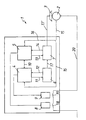
- the single FIGURE shows the control device according to the invention 1. Zur Simplification, only the invention relevant components are shown. Recognizable is the drive motor 2 of an escalator, not shown or a moving walkway as well as the brake 3 which can be brought into operative connection therewith.
- the control device 1 comprises two mutually monitoring Microprocessors 4,5. Each of the microprocessors 4,5 stands with a Driver element 6.7 in operative connection. In addition, everyone works Microprocessors 4,5 on an associated relay 8,9 a.
- the processors 4, 5 are connected to one another via a signal line 10 Active connection, so that their performance are monitored each other can. Via further lines 11,12,13,14, the processors see 4,5 with the associated driver elements 6,7 in operative connection. Other signal lines 15,16 are between the drive motor 2 and the respective processor 4,5 intended.
- the driver elements 6, 7 are connected to one another via a line 17 in operative connection, which as a continuation of the same as line 17 'to not further illustrated switching elements of the brake 3 acts.
- the relays are 8.9 via switches 18,19 and a single line 20 to the drive motor. 2 connected. For previously occurring malfunctions in the area of Passenger conveyor system, the brake would be 3 suddenly collapsed, which also the engine 2 would have been shut down. The full braking would, however, under Cause circumstances to be present on the passenger conveyor People may fall behind as a sudden delay the passenger conveyor system begins.
- the scheme is based on the known fuzzy logic, wherein in the field the processors minimum and maximum values are stored, so that at least one mean value given in accordance with the safety standards can be generated at which the control scheme for the brake. 3 oriented.
- the processors monitor 4,5 each other, so that they always have the same data.
- Control of the brake 3 under tension i. the brake 3 is relieved, so that the drive motor 2 can work without restraint.
- a Malfunction i. provided both processors 4.5 this malfunction have determined and the data match is identical, are appropriate Signals passed to the driver elements 6,7, the brake 3 now abruptly to incite.
Abstract
Description
Die Erfindung betrifft ein Verfahren sowie eine Einrichtung zur Regelung der Bremse(n) einer Personenförderanlage, wie einer Rolltreppe oder eines Rollsteiges.The invention relates to a method and a device for controlling the brake (s) of a Passenger conveyor system, such as an escalator or a moving walkway.
Ein derartiges Verfahren sowie eine derartige Einrichtung geht aus der DE-A- 1993 5521 hervor.Such a method and such a device goes out DE-A-1993 5521.
Rolltreppen und Rollsteige müssen gemäß geltenden in- und ausländischen Sicherheitsvorschriften so ausgerüstet sein, daß sie selbsttätig stillgesetzt werden, bevor die Geschwindigkeit beispielsweise den 1,2-fachen Wert der Nenngeschwindigkeit überschreitet. In gleicher Weise muß eine Stillsetzung herbeigeführt werden, sobald Störungen im Bereich der Rolltreppen oder des Rollsteiges auftreten, beispielsweise wenn ein Sicherheitsschalter betätigt wird.Escalators and moving walkways must be in accordance with applicable domestic and foreign Safety regulations must be equipped so that they are automatically shut down for example, before the speed is 1.2 times the value of Nominal speed exceeds. In the same way, a shutdown must be brought about as soon as disturbances in the area of the escalators or the Roll climbing occur, for example, when a safety switch is pressed becomes.
Vielfach kommen bei Rolltreppen und Rollsteigen mechanische Bremsen, wie Backenbremsen, zum Einsatz, die bei derzeitiger Ansteuerung beim Auftreten eines Fehlers schlagartig einfallen.In many cases, mechanical escalators are used on escalators and moving walks Jaw brakes, used, the current control when occurring of a mistake.
Personen die auf der Rolltreppe oder dem Rollsteig befindlich sind, können, bedingt durch das schlagartige Einfallen der Bremse, unter Umständen hinfallen und sich verletzen.People who are on the escalator or the platform, can, due to the sudden collapse of the brake, possibly fall down and hurt yourself.
Weiterhin nachteilig ist, daß sich bei Verschleiß der Bremsbeläge der Bremsweg verlängert, auch wenn die Bremse schlagartig einfällt.Another disadvantage is that in case of wear of the brake pads Braking distance extended, even if the brake suddenly occurs.
Ziel des Erfindungsgegenstandes ist es, ein Verfahren und eine Einrichtung zur Regelung der Bremse(n) einer Personenförderanlage, wie einer Rolltreppe oder eines Rollsteiges zu konzipieren, die auch bei Verschleiß von Bremsbelägen einen weitestgehend gleichen Bremsweg erlaubt, ohne daß es zu Personenschäden kommt. The aim of the subject invention is to provide a method and a device for Control of the brake (s) of a passenger conveyor system, such as an escalator or to conceive of a moving walkway, even when wearing brake pads a largely the same braking distance allowed without it too Personal injury comes.
Dieses Ziel wird erreicht durch ein Verfahren zur Regelung der jeweiligen Bremse einer Personenförderanlage, wie einer Rolltreppe oder eines Rollsteiges, indem die Steuersignale des Antriebsmotors und der Bremse mittels mehrerer Prozessoren überwacht werden, bei auftretenden Funktionsstörungen im Bereich der Personenförderanlage, die Bremse schlagartig zum Einfall gebracht wird, bei Erkennung von Verzögerungswerten die Bremse(n) definiert entlastet und sodann über die Prozessoren innerhalb eines vorgebbaren Zeitinervalles die Personenförderanlage stillgesetzt wird.This objective is achieved through a process of regulation of the respective Brake of a passenger conveyor system, such as an escalator or a moving walkway, by the control signals of the drive motor and the brake by means of several Processors are monitored in case of malfunction occurring in the Area of passenger transport system, the brake suddenly brought to the idea If the deceleration value is detected, the brake (s) is relieved in a defined way and then over the processors within a predetermined time interval the Passenger conveyor system is shut down.
Vorteilhafte Weiterbildungen des Erfindungsgegenstandes sind den zugehörigen verfahrensgemäßen Unteransprüchen zu entnehmen.Advantageous developments of the subject invention are the to refer to associated subclaims.
Dieses Ziel wird auch erreicht durch eine Einrichtung zur Regelung der jeweiligen Bremse einer Personenförderanlage, mit mindestens zwei sich gegenseitig überwachenden Prozessoren, die über Treiberelemente mit Schaltelementen der Bremse verbunden sind.This objective is also achieved by a mechanism for regulating the respective brake of a passenger conveyor system, with at least two themselves mutually supervising processors using driver elements Switching elements of the brake are connected.
Vorteilhafte Weiterbildungen der erfindungsgemäßen Einrichtung sind den zugehörigen gegenständlichen Unteransprüchen zu entnehmen.Advantageous developments of the device according to the invention are the to refer to associated subclaims.
Das Prinzip der erfindungsgemäßen Regeleinrichtung beruht somit in Anlehnung an die im In- und Ausland geltenden Sicherheitsvorschriften. Diese bei Rolltreppen und Rollsteigen bisher noch nicht verwirklichte Art der Regelung der Bremse(n) entspricht dem heutigen technischen Stand und genügt auch den einschlägigen in- und ausländischen Sicherheitsstandards.The principle of the control device according to the invention is thus based in Based on national and international safety regulations. These in escalators and moving walks not yet realized type of Regulation of the brake (s) corresponds to the current state of the art and also satisfies the relevant domestic and foreign safety standards.
Im Hinblick darauf, daß die Ansteuerung der Schaltelemente der Bremse(n) im Niederspannungsbereich (24 V) realisiert werden kann, ist in diesem Bereich auch keine bisher zum Einsatz gelangte 220 V-Spannung mehr gegeben, wodurch die Sicherheit weiterhin erhöht wird. In view of the fact that the control of the switching elements of the brake (s) in Low voltage range (24 V) can be realized is in this area no more 220 V voltage has been used so far, which further enhances safety.
Es kommen mindestens zwei Mikroprozessoren zum Einsatz, die sich einerseits gegenseitig überwachen und andererseits Steuersignale der Bremse sowie des Antriebsmotors kontrollieren, bzw. auf selbige regelnd einwirken.At least two microprocessors are used, on the one hand monitor each other and on the other hand control signals of the brake and the Check or act on the drive motor.
Die Regelung basiert auf der an sich bekannten Fuzzy-Logik. Im Speicher sind unterschiedlichste Minimal- und Maximalwerte abgelegt, durch welche mindestens ein Mittelwert generiert wird, an welchem sich die Prozessoren bzw. des Bremsverhaltens orientieren.The control is based on the known fuzzy logic. In the store are various minimum and maximum values stored by which at least one mean value is generated at which the processors or the braking behavior.
Die jeweilige Bremse bleibt wie beim bisherigen Stand der Technik gelüftet. Wie bisher fällt auch die Bremse bei auftretenden Störungen schlagartig ein. Sind zusätzliche Störungen im Bereich der Regeleinheit (mindestens eines Prozessors) gegeben, d.h. wird über die Regeleinheit keine Verzögerung festgestellt, bleibt die Bremse eingefallen und bewegt sich somit im bekannten Stand der Technik.The respective brake remains released as in the prior art. As in the past, the brake will suddenly drop when faults occur. Are additional disturbances in the area of the control unit (at least one Processor), i. is via the control unit no delay determined, the brake is retracted and thus moves in the known State of the art.
Dies ist jedoch eher unwahrscheinlich, da infolge Redundanz der Prozessoren ein Verzögerungswert festgestellt wird, so daß das Regelschema (Fuzzy-Logik) in Gang gesetzt werden kann. Das Regelschema sieht vor, daß die jeweilige Bremse definiert wieder gelüftet wird, wodurch der Zustand der Vollbremsung zugunsten der auf der Rolltreppe bzw. dem Rollsteig befindlichen Personen verbessert wird. Die auf der Rolltreppe bzw. dem Rollsteig befindlichen Personen bemerken somit zwar, daß die Bremse einfällt, in dem einen kurzen Moment eine stärkere Verzögerung stattfindet. Sobald der oder die Prozessoren die Verzögerung erkannt haben, wird die jeweilige Bremse wieder entlüftet, so daß innerhalb eines dem Sicherheitsstandard entsprechenden Bremsweges und einstellbaren Zeitintervall die Bremse dann geregelt stillgesetzt werden kann, ohne daß es zu Personenschäden kommt. However, this is unlikely due to redundancy of the processors a delay value is detected so that the control scheme (fuzzy logic) can be set in motion. The rule scheme stipulates that the respective Brake defined is aired again, causing the condition of full braking in favor of the persons on the escalator or the platform is improved. The located on the escalator or the platform Persons thus notice that the brake comes in, in which a short Moment a stronger delay takes place. Once the or the Processors that have detected the delay will recover the respective brake vented so that within a safety standard corresponding Braking distance and adjustable time interval the brake then regulated can be stopped without causing personal injury.
Die sich gegenseitig überwachenden Prozessoren bilden ein sogenanntes Sicherheitssystem. Jeder der Prozessoren steuert mindestens ein Treiberelement an, da die Prozessoren selber nicht in der Lage sind, 24 V Signale zu generieren. Dies findet im Bereich des jeweiligen Treiberelementes statt, dessen 24 V Signal wiederum dem jeweiligen Schaltelement der jeweiligen Bremse als Ansteuerspannung dient. Das Schaltelement ist in der Regel ein Bremsmagnet.The mutually supervising processors form a so-called Security system. Each of the processors controls at least one Driver element, since the processors themselves are not able to 24 V Generate signals. This takes place in the area of the respective driver element instead, whose 24 V signal in turn the respective switching element of each brake serves as a drive voltage. The switching element is in the Usually a brake magnet.
Die Treiberelemente stellen ein zwei- oder mehrkanaliges System dar, das auch bei Ausfall eines Prozessors die Vollbremsung herbei führen kann. Insofern ist auch bei Ausfall eines Prozessors in jedem Fall die bereits im Stand der Technik bekannte Vollbremsung der Personenförderanlage sichergestellt.The driver elements represent a two- or multi-channel system, the even in case of failure of a processor full braking can cause. In this respect, even in the event of a processor failure in any case already in the state the technology known full braking the passenger conveyor system ensured.
Die Prozessoren wirken darüber hinaus auf Steuerrelais ein, über welche der Antriebsmotor abgeschaltet werden kann, sobald die Bremse einfällt. Damit ist der Vorteil verbunden, daß die wirkende Bremskraft nicht gegen den laufenden Motor arbeiten muß und somit gegebenenfalls hier weitere Schäden hervorruft.The processors also act on control relays via which the Drive motor can be switched off as soon as the brake is applied. This is connected the advantage that the braking force is not against the current Motor must work and thus possibly causes further damage here.
Der Erfindungsgegenstand ist anhand eines Ausführungsbeispieles in der Zeichnung dargestellt und wird wie folgt beschrieben.The subject invention is based on an embodiment in the Drawing and is described as follows.
Die einzige Figur zeigt die erfindungsgemäße Regeleinrichtung 1. Zur
Vereinfachung sind lediglich die erfindungsrelevanten Bauteile dargestellt.
Erkennbar ist der Antriebsmotor 2 einer nicht weiter dargestellten Rolltreppen
oder eines Rollsteiges sowie die damit in Wirkverbindung bringbare Bremse 3.
Die Regeleinrichtung 1 umfaßt zwei sich gegenseitig überwachende
Mikroprozessoren 4,5. Jeder der Mikroprozessoren 4,5 steht mit einem
Treiberelement 6,7 in Wirkverbindung. Darüber hinaus wirkt jeder der
Mikroprozessoren 4,5 auf ein zugeordnetes Relais 8,9 ein. The single FIGURE shows the control device according to the invention 1. Zur
Simplification, only the invention relevant components are shown.
Recognizable is the drive motor 2 of an escalator, not shown
or a moving walkway as well as the
Die Prozessoren 4,5 stehen über eine Signalleitung 10 miteinander in
Wirkverbindung, so daß deren Betriebsverhalten gegenseitig überwacht werden
kann. Über weitere Leitungen 11,12,13,14, sehen die Prozessoren 4,5 mit den
zugehörigen Treiberelementen 6,7 in Wirkverbindung. Weitere Signalleitungen
15,16 sind zwischen dem Antriebsmotor 2 und dem jeweiligen Prozessor 4,5
vorgesehen. Die Treiberelemente 6,7 stehen über eine Leitung 17 miteinander
in Wirkverbindung, welche als Fortsetzung derselben als Leitung 17' auf nicht
weiter dargestellte Schaltelemente der Bremse 3 einwirkt. Die Relais 8,9 sind
über Schalter 18,19 sowie eine einzige Leitung 20 mit dem Antriebsmotor 2
verbunden. Bei bisher auftretenden Funktionsstörungen im Bereich der
Personenförderanlage wäre die Bremse 3 schlagartig eingefallen, wodurch auch
der Motor 2 stillgesetzt worden wäre. Die Vollbremsung würde jedoch unter
Umständen dazu führen, daß auf der Personenförderanlage sich befindende
Personen unter Umständen hinfallen können, da eine schlagartige Verzögerung
der Personenförderanlage einsetzt.The
Hier setzt nun die Erfindung an, indem ein geregeltes Abbremsverhalten konzipiert wird, das dennoch die Sicherheitsstandards erfüllt.This is where the invention begins by a controlled braking behavior that still meets safety standards.
Die Regelung basiert auf der an sich bekannten Fuzzy-Logik, wobei im Bereich
der Prozessoren Minimal- und Maximalwerte abgespeichert sind, so daß
mindestens ein entsprechend den Sicherheitsstandards gegebener Mittelwert
generiert werden kann, an welchem sich das Regelschema für die Bremse 3
orientiert. Wie bereits angesprochen, überwachen sich die Prozessoren 4,5
gegenseitig, so daß selbige stets den gleichen Datenstand haben. Solange die
Personenförderanlage störungsfrei arbeitet, bleibt das nicht weiter dargestellte
Steuerelement der Bremse 3 unter Spannung d.h. die Bremse 3 ist entlastet,
so daß der Antreibsmotor 2 ungebremst arbeiten kann. Im Falle einer
Betriebsstörung, d.h. sofern beide Prozessoren 4,5 diese Betriebsstörung
festgestellt haben und der Datenabgleich identisch ist, werden entsprechende
Signale auf die Treiberelemente 6,7 geleitet, die die Bremse 3 nun schlagartig
zum Einfall bringen. Gleichzeitig wird über die Relais 8,9 sowie die Leitung 20
der Antriebsmotor 2 stillgesetzt, damit die einwirkende Bremsenergie nicht
gegen den laufenden Motor arbeiten muß. Stellen die Prozessoren 4,5 nun
Verzögerungswerte im Bereich des Antriebsmotors 2 fest, setzt daß
erfindungsgemäße Regelschema ein, nämlich, daß die Bremse 3 über die
zugehörigen Schaltelemente definiert wieder entlastet wird und innerhalb eines
vorgegebenen, dem Sicherheitsstandard entsprechenden Bremsweges sowie
Zeitintervalles die Stillsetzung der Personenförderanlage herbeigeführt wird. Die
sich auf der Personenförderanlage befindenden Personen verspüren somit einen
kurzzeitigen Verzögerungsimpuls, der jedoch nicht durchgängig ist, vielmehr
wieder aufgehoben wird, so daß es infolge der erfindungsgemäßen Regelung
nicht mehr zu Personenschäden kommen kann. Sollte einer der Prozessoren
4,5 ausfallen, d.h. die beiden Prozessoren 4,5 nicht kompatible Datensätze
austauschen, wird über den zugehörigen Treiber 6 oder 7 und die Leitung 17
bzw. 17' die Bremse 3 schlagartig zum Einfallen gebracht, d.h. eine - wie im
Stand der Technik bekannte - Vollbremsung herbeigeführt.The scheme is based on the known fuzzy logic, wherein in the field
the processors minimum and maximum values are stored, so that
at least one mean value given in accordance with the safety standards
can be generated at which the control scheme for the brake. 3
oriented. As already mentioned, the processors monitor 4,5
each other, so that they always have the same data. As long as the
Passenger conveyor system works trouble-free, remains not shown
Control of the
Insofern ist sichergestellt, daß neben der komfortablen Regelung der Bremse 3
der Personenförderanlage nun auch bei Ausfall der Regeleinheit 1 (Prozessor 4
oder 5) der bisherige Sicherheitsstandard, nämlich die Vollbremsung
gewährleistet werden kann.In this respect, it is ensured that in addition to the comfortable control of the
Claims (9)
- A method for regulating the respective break (3) of a pedestrian conveyor, such as an escalator or a moving walkway, in which the control signals of the drive motor (2) and the break (3) are monitored by means of several processors (4, 5), the break (3) is abruptly applied, when malfunctions happen within the pedestrian conveyor, the break (3) is relieved in a defined way, if deceleration values are detected, and then the pedestrian conveyor is stopped by means of the processors (4, 5) within a pre-determinable time interval.
- A method according to claim 1, characterized in that the processors (4, 5) mutually monitor each other.
- A method according to claim 1 or 2, characterized in that each processor (4, 5) triggers at least one drive element (6, 7), which generates a 24 V signal, and which cooperates with the control elements of the break (3).
- A method according to one of the claims 1 through 3, characterized in that all processors (4, 5) act upon the drive motor (2) via associated relays (8, 9) and stop this one, when the break (3) is applied.
- A method according to one of the claims 1 through 4, characterized in that the regulation is carried out on the base of the Fuzzy logic.
- A method according to one of the claims 1 through 5, characterized in that even if one processor (4 or 5) breaks down, the break (3) will be abruptly applied via the drive element(s) (6, 7).
- A device for regulating the respective break (3) of a pedestrian conveyor comprising at least two processors (4, 5), which mutually monitor each other, and which are connected to control elements of the break (3) via drive elements (6, 7).
- A device according to claim 7, characterized in that the processors (4, 5) cooperate with associated relays (8, 9), which are connected to the drive motor (2) of the pedestrian conveyor.
- A device according to claim 7 or 8, characterized in that each drive element (6, 7) generates a 24 V signal, which serves as triggering voltage for the control element of the respective break (3).
Applications Claiming Priority (3)
| Application Number | Priority Date | Filing Date | Title |
|---|---|---|---|
| DE10018887A DE10018887B4 (en) | 2000-04-14 | 2000-04-14 | Method and device for controlling the brake (s) of a passenger conveyor system |
| DE10018887 | 2000-04-14 | ||
| PCT/EP2001/002662 WO2001079106A1 (en) | 2000-04-14 | 2001-03-09 | Method and device for adjusting the brake(s) of a device for transporting people |
Publications (3)
| Publication Number | Publication Date |
|---|---|
| EP1274644A1 EP1274644A1 (en) | 2003-01-15 |
| EP1274644B1 true EP1274644B1 (en) | 2005-01-12 |
| EP1274644B2 EP1274644B2 (en) | 2013-06-12 |
Family
ID=7638977
Family Applications (1)
| Application Number | Title | Priority Date | Filing Date |
|---|---|---|---|
| EP01925409.3A Expired - Lifetime EP1274644B2 (en) | 2000-04-14 | 2001-03-09 | Method and device for adjusting the brake(s) of a device for transporting people |
Country Status (9)
| Country | Link |
|---|---|
| US (1) | US6766893B2 (en) |
| EP (1) | EP1274644B2 (en) |
| CN (1) | CN1220619C (en) |
| AT (1) | ATE286848T1 (en) |
| AU (1) | AU2001252176A1 (en) |
| DE (2) | DE10018887B4 (en) |
| ES (1) | ES2231476T5 (en) |
| HK (1) | HK1054366B (en) |
| WO (1) | WO2001079106A1 (en) |
Families Citing this family (10)
| Publication number | Priority date | Publication date | Assignee | Title |
|---|---|---|---|---|
| JP2009215047A (en) * | 2008-03-12 | 2009-09-24 | Toshiba Elevator Co Ltd | Control device for elevator |
| DE102008047514A1 (en) * | 2008-09-12 | 2010-03-25 | Pilz Gmbh & Co. Kg | disk |
| FI120986B (en) * | 2008-11-03 | 2010-05-31 | Kone Corp | Arrangement and method of monitoring brake operation and lift system |
| DE102009034345B4 (en) * | 2009-07-23 | 2013-01-03 | Kone Corp. | Method and device for operating a passenger transport device |
| US7950514B1 (en) * | 2009-11-06 | 2011-05-31 | Kone Corporation | Apparatus and method for variable torque braking of escalators and moving walkways |
| DE102012003178B4 (en) * | 2012-02-17 | 2018-03-22 | Kone Corp. | Device for monitoring the function of an escalator or moving walkway |
| US10035680B2 (en) | 2013-02-14 | 2018-07-31 | Otis Elevator Company | Elevator safety circuit including non forced guided relay |
| CN105813970B (en) | 2013-12-12 | 2019-04-12 | 奥的斯电梯公司 | For the security system used in drive system |
| DE112021002649T5 (en) * | 2020-09-02 | 2023-03-16 | Hl Mando Corporation | ELECTRICAL CONTROL UNIT OF AN ELECTRONIC PARKING BRAKE SYSTEM |
| DE112021003249T5 (en) * | 2020-09-02 | 2023-03-30 | Hl Mando Corporation | ELECTRICAL CONTROL UNIT OF AN ELECTRIC PARKING BRAKE SYSTEM |
Family Cites Families (19)
| Publication number | Priority date | Publication date | Assignee | Title |
|---|---|---|---|---|
| DE2003951A1 (en) * | 1970-01-29 | 1971-08-05 | Gerhard Bubenzer | Braking device for braking a rotating shaft |
| CA995792A (en) * | 1972-09-29 | 1976-08-24 | Michio Imanaka | Braking system for an electrically-operated road such as an escalator |
| FR2464912A1 (en) * | 1979-09-14 | 1981-03-20 | Najman Alain | Electronic braking control of escalator - uses triac to inject variable current via rectifier to stator of induction motor for braking |
| JPS57141377A (en) * | 1981-02-27 | 1982-09-01 | Hitachi Ltd | Driving device for man conveyor |
| US4588065A (en) * | 1984-08-27 | 1986-05-13 | Westinghouse Electric Corp. | Escalator with controlled brake |
| JPH0729749B2 (en) * | 1989-07-21 | 1995-04-05 | 株式会社日立製作所 | Passenger conveyor control device |
| JP2523927B2 (en) * | 1990-04-11 | 1996-08-14 | 株式会社日立製作所 | Passenger conveyor control device |
| US5272428A (en) * | 1992-02-24 | 1993-12-21 | The United States Of America As Represented By The U.S. Environmental Protection Agency | Fuzzy logic integrated control method and apparatus to improve motor efficiency |
| US5482153A (en) * | 1994-07-25 | 1996-01-09 | Otis Elevator Company | Operation panel for a passenger conveying device |
| US5564550A (en) * | 1994-09-20 | 1996-10-15 | Otis Elevator Company | Adapting escalator speed to traffic using fuzzy logic |
| US5708416A (en) * | 1995-04-28 | 1998-01-13 | Otis Elevator Company | Wireless detection or control arrangement for escalator or moving walk |
| US5886497A (en) * | 1995-05-26 | 1999-03-23 | Otis Elevator Company | Control arrangement for escalator or moving walk |
| DE19541410C2 (en) * | 1995-11-07 | 1999-04-01 | O & K Rolltreppen Gmbh | Standby switchgear for passenger conveyor systems |
| DE19754141C2 (en) * | 1997-12-04 | 2000-05-25 | O & K Rolltreppen Gmbh | Safety device for escalators and moving walks |
| DE19803433A1 (en) * | 1998-01-29 | 1999-08-05 | Militzer Otto Michael Dr Ing | Braking magnet control device for escalator, lift or moving walkway |
| DE19803899C2 (en) * | 1998-02-02 | 2000-04-13 | O & K Rolltreppen Gmbh | Process for braking escalators or moving walks and braking device for escalators or moving walks |
| DE19935521C2 (en) * | 1999-07-28 | 2001-07-19 | Kone Corp | Method for controlling the brake (s) of an escalator or moving walk |
| US6267219B1 (en) * | 2000-08-11 | 2001-07-31 | Otis Elevator Company | Electronic safety system for escalators |
| FR2827051B1 (en) * | 2001-07-09 | 2003-10-24 | Mediterranee Const Ind | METHOD AND SYSTEM FOR SECURE VIDEO DETECTION FOR THE AUTOMATIC CONTROL OF A MECHANICAL SYSTEM SUCH AS A MOVING WALKWAY OR MECHANICAL STAIRCASE |
-
2000
- 2000-04-14 DE DE10018887A patent/DE10018887B4/en not_active Expired - Fee Related
-
2001
- 2001-03-09 AT AT01925409T patent/ATE286848T1/en active
- 2001-03-09 CN CNB018110207A patent/CN1220619C/en not_active Expired - Fee Related
- 2001-03-09 AU AU2001252176A patent/AU2001252176A1/en not_active Abandoned
- 2001-03-09 WO PCT/EP2001/002662 patent/WO2001079106A1/en active IP Right Grant
- 2001-03-09 DE DE50105066T patent/DE50105066D1/en not_active Expired - Lifetime
- 2001-03-09 EP EP01925409.3A patent/EP1274644B2/en not_active Expired - Lifetime
- 2001-03-09 ES ES01925409T patent/ES2231476T5/en not_active Expired - Lifetime
-
2003
- 2003-01-16 US US10/345,153 patent/US6766893B2/en not_active Expired - Fee Related
- 2003-09-16 HK HK03106643.5A patent/HK1054366B/en not_active IP Right Cessation
Also Published As
| Publication number | Publication date |
|---|---|
| ATE286848T1 (en) | 2005-01-15 |
| CN1436149A (en) | 2003-08-13 |
| ES2231476T5 (en) | 2013-10-31 |
| US6766893B2 (en) | 2004-07-27 |
| US20030102199A1 (en) | 2003-06-05 |
| DE10018887A1 (en) | 2001-10-25 |
| HK1054366A1 (en) | 2003-11-28 |
| EP1274644A1 (en) | 2003-01-15 |
| CN1220619C (en) | 2005-09-28 |
| DE50105066D1 (en) | 2005-02-17 |
| EP1274644B2 (en) | 2013-06-12 |
| WO2001079106A1 (en) | 2001-10-25 |
| AU2001252176A1 (en) | 2001-10-30 |
| HK1054366B (en) | 2005-12-09 |
| DE10018887B4 (en) | 2005-02-10 |
| ES2231476T3 (en) | 2005-05-16 |
Similar Documents
| Publication | Publication Date | Title |
|---|---|---|
| EP2651809B1 (en) | Actuation of an intercepting apparatus | |
| EP2315717B1 (en) | Method for monitoring a braking system in a lift assembly and corresponding brake monitor for a lift assembly | |
| DE602005002615T2 (en) | Device for protection against unwanted braking for electromechanical brakes | |
| EP1274644B1 (en) | Method and device for adjusting the brake(s) of a device for transporting people | |
| EP1053206B1 (en) | Braking device and method for braking escalators or moving walkways | |
| EP0320602B1 (en) | Overload warning device for a trailer brake | |
| EP2651611A1 (en) | Safety device for a handling apparatus, in particular an industrial robot, and method for operating the safety device | |
| EP2060459B1 (en) | Braking system for a railway vehicle and method of braking the railway vehicle and brake control for such a braking system | |
| DE10310480B4 (en) | Method and device for controlling a door drive | |
| DE19756328C2 (en) | Hydraulic tensioning device for belt conveyor | |
| EP3215449B1 (en) | Elevator with a brake device | |
| EP1187746B1 (en) | Brake system for a motor vehicle | |
| EP2175552A1 (en) | Method for operating a drive device and drive device for implementing the method | |
| DE1527637B2 (en) | Device for slowing down the pressure and releasing the rollers in a rolling mill | |
| EP0726643B1 (en) | Method and device for braking the electric main drive of a printing machine | |
| WO2018172120A1 (en) | Braking device for rail vehicles and method for braking rail vehicles | |
| DE10254608B4 (en) | drive system | |
| DE3632962C1 (en) | Control device for the brake and/or drive of a conveying system | |
| DE3917594C2 (en) | elevator brake | |
| DE202016101183U1 (en) | Elevator with a safety controller for directly influencing the braking force | |
| DE212020000575U1 (en) | Safety cabin device for elevator | |
| DE102015100798A1 (en) | Safety device, in particular safety rope | |
| DE102008009040B4 (en) | Belt retractor with electric pre-tensioner and method for operating an electric pre-tensioner | |
| DE102016010327A1 (en) | Storage operating device and method for controlling a storage and retrieval device | |
| DE102017204123A1 (en) | Method for braking a machine and a machine |
Legal Events
| Date | Code | Title | Description |
|---|---|---|---|
| PUAI | Public reference made under article 153(3) epc to a published international application that has entered the european phase |
Free format text: ORIGINAL CODE: 0009012 |
|
| 17P | Request for examination filed |
Effective date: 20020918 |
|
| AK | Designated contracting states |
Kind code of ref document: A1 Designated state(s): AT BE CH CY DE DK ES FI FR GB GR IE IT LI LU MC NL PT SE TR |
|
| AX | Request for extension of the european patent |
Free format text: AL;LT;LV;MK;RO;SI |
|
| RIN1 | Information on inventor provided before grant (corrected) |
Inventor name: TAUTZ, ANDREAS Inventor name: NEUMANN, SASCHA |
|
| RIN1 | Information on inventor provided before grant (corrected) |
Inventor name: TAUTZ, ANDREAS Inventor name: NEUMANN, SASCHA |
|
| 17Q | First examination report despatched |
Effective date: 20040220 |
|
| GRAP | Despatch of communication of intention to grant a patent |
Free format text: ORIGINAL CODE: EPIDOSNIGR1 |
|
| GRAS | Grant fee paid |
Free format text: ORIGINAL CODE: EPIDOSNIGR3 |
|
| GRAA | (expected) grant |
Free format text: ORIGINAL CODE: 0009210 |
|
| AK | Designated contracting states |
Kind code of ref document: B1 Designated state(s): AT BE CH CY DE DK ES FI FR GB GR IE IT LI LU MC NL PT SE TR |
|
| PG25 | Lapsed in a contracting state [announced via postgrant information from national office to epo] |
Ref country code: IT Free format text: LAPSE BECAUSE OF FAILURE TO SUBMIT A TRANSLATION OF THE DESCRIPTION OR TO PAY THE FEE WITHIN THE PRE;WARNING: LAPSES OF ITALIAN PATENTS WITH EFFECTIVE DATE BEFORE 2007 MAY HAVE OCCURRED AT ANY TIME BEFORE 2007. THE CORRECT EFFECTIVE DATE MAY BE DIFFERENT FROM THE ONE RECORDED.SCRIBED TIME-LIMIT Effective date: 20050112 Ref country code: NL Free format text: LAPSE BECAUSE OF FAILURE TO SUBMIT A TRANSLATION OF THE DESCRIPTION OR TO PAY THE FEE WITHIN THE PRESCRIBED TIME-LIMIT Effective date: 20050112 Ref country code: IE Free format text: LAPSE BECAUSE OF FAILURE TO SUBMIT A TRANSLATION OF THE DESCRIPTION OR TO PAY THE FEE WITHIN THE PRESCRIBED TIME-LIMIT Effective date: 20050112 Ref country code: TR Free format text: LAPSE BECAUSE OF FAILURE TO SUBMIT A TRANSLATION OF THE DESCRIPTION OR TO PAY THE FEE WITHIN THE PRESCRIBED TIME-LIMIT Effective date: 20050112 Ref country code: FI Free format text: LAPSE BECAUSE OF FAILURE TO SUBMIT A TRANSLATION OF THE DESCRIPTION OR TO PAY THE FEE WITHIN THE PRESCRIBED TIME-LIMIT Effective date: 20050112 |
|
| REG | Reference to a national code |
Ref country code: GB Ref legal event code: FG4D Free format text: NOT ENGLISH |
|
| REG | Reference to a national code |
Ref country code: CH Ref legal event code: NV Representative=s name: ABACUS PATENTANWAELTE KLOCKE SPAETH BARTH Ref country code: CH Ref legal event code: EP |
|
| GBT | Gb: translation of ep patent filed (gb section 77(6)(a)/1977) |
Effective date: 20050112 |
|
| REF | Corresponds to: |
Ref document number: 50105066 Country of ref document: DE Date of ref document: 20050217 Kind code of ref document: P |
|
| REG | Reference to a national code |
Ref country code: IE Ref legal event code: FG4D Free format text: GERMAN |
|
| PG25 | Lapsed in a contracting state [announced via postgrant information from national office to epo] |
Ref country code: CY Free format text: LAPSE BECAUSE OF FAILURE TO SUBMIT A TRANSLATION OF THE DESCRIPTION OR TO PAY THE FEE WITHIN THE PRESCRIBED TIME-LIMIT Effective date: 20050309 Ref country code: LU Free format text: LAPSE BECAUSE OF NON-PAYMENT OF DUE FEES Effective date: 20050309 |
|
| PG25 | Lapsed in a contracting state [announced via postgrant information from national office to epo] |
Ref country code: MC Free format text: LAPSE BECAUSE OF NON-PAYMENT OF DUE FEES Effective date: 20050331 Ref country code: BE Free format text: LAPSE BECAUSE OF NON-PAYMENT OF DUE FEES Effective date: 20050331 |
|
| RAP2 | Party data changed (patent owner data changed or rights of a patent transferred) |
Owner name: KONE CORPORATION |
|
| PG25 | Lapsed in a contracting state [announced via postgrant information from national office to epo] |
Ref country code: SE Free format text: LAPSE BECAUSE OF FAILURE TO SUBMIT A TRANSLATION OF THE DESCRIPTION OR TO PAY THE FEE WITHIN THE PRESCRIBED TIME-LIMIT Effective date: 20050412 Ref country code: DK Free format text: LAPSE BECAUSE OF FAILURE TO SUBMIT A TRANSLATION OF THE DESCRIPTION OR TO PAY THE FEE WITHIN THE PRESCRIBED TIME-LIMIT Effective date: 20050412 |
|
| REG | Reference to a national code |
Ref country code: ES Ref legal event code: FG2A Ref document number: 2231476 Country of ref document: ES Kind code of ref document: T3 |
|
| NLT2 | Nl: modifications (of names), taken from the european patent patent bulletin |
Owner name: KONE CORPORATION |
|
| NLV1 | Nl: lapsed or annulled due to failure to fulfill the requirements of art. 29p and 29m of the patents act | ||
| REG | Reference to a national code |
Ref country code: GB Ref legal event code: ERR Free format text: NOTIFICATION HAS BOW BEEN RECEIVED FROM THE EUROPEAN PATENT OFFICE THAT THE CORRECT NAME OF THE APPLICANT/PROPRIETOR IS: KONE CORPORATION THIS CORRECTION WAS PUBLISHED IN THE EUROPEAN PATENT BULLETIN 05/14 DATED 20050406. |
|
| REG | Reference to a national code |
Ref country code: IE Ref legal event code: FD4D |
|
| BERE | Be: lapsed |
Owner name: *KONE CORP. Effective date: 20050331 |
|
| PLBI | Opposition filed |
Free format text: ORIGINAL CODE: 0009260 |
|
| PLAX | Notice of opposition and request to file observation + time limit sent |
Free format text: ORIGINAL CODE: EPIDOSNOBS2 |
|
| 26 | Opposition filed |
Opponent name: INVENTIO AG Effective date: 20051012 |
|
| ET | Fr: translation filed | ||
| PLBB | Reply of patent proprietor to notice(s) of opposition received |
Free format text: ORIGINAL CODE: EPIDOSNOBS3 |
|
| BERE | Be: lapsed |
Owner name: *KONE CORP. Effective date: 20050331 |
|
| PG25 | Lapsed in a contracting state [announced via postgrant information from national office to epo] |
Ref country code: PT Free format text: LAPSE BECAUSE OF NON-PAYMENT OF DUE FEES Effective date: 20050612 |
|
| PG25 | Lapsed in a contracting state [announced via postgrant information from national office to epo] |
Ref country code: GR Free format text: LAPSE BECAUSE OF NON-PAYMENT OF DUE FEES Effective date: 20050112 |
|
| PLAY | Examination report in opposition despatched + time limit |
Free format text: ORIGINAL CODE: EPIDOSNORE2 |
|
| PLAH | Information related to despatch of examination report in opposition + time limit modified |
Free format text: ORIGINAL CODE: EPIDOSCORE2 |
|
| PLBC | Reply to examination report in opposition received |
Free format text: ORIGINAL CODE: EPIDOSNORE3 |
|
| APAH | Appeal reference modified |
Free format text: ORIGINAL CODE: EPIDOSCREFNO |
|
| APBM | Appeal reference recorded |
Free format text: ORIGINAL CODE: EPIDOSNREFNO |
|
| APBP | Date of receipt of notice of appeal recorded |
Free format text: ORIGINAL CODE: EPIDOSNNOA2O |
|
| APBQ | Date of receipt of statement of grounds of appeal recorded |
Free format text: ORIGINAL CODE: EPIDOSNNOA3O |
|
| APAH | Appeal reference modified |
Free format text: ORIGINAL CODE: EPIDOSCREFNO |
|
| APAY | Date of receipt of notice of appeal deleted |
Free format text: ORIGINAL CODE: EPIDOSDNOA2O |
|
| APBA | Date of receipt of statement of grounds of appeal deleted |
Free format text: ORIGINAL CODE: EPIDOSDNOA3O |
|
| APBM | Appeal reference recorded |
Free format text: ORIGINAL CODE: EPIDOSNREFNO |
|
| APBP | Date of receipt of notice of appeal recorded |
Free format text: ORIGINAL CODE: EPIDOSNNOA2O |
|
| APBQ | Date of receipt of statement of grounds of appeal recorded |
Free format text: ORIGINAL CODE: EPIDOSNNOA3O |
|
| APBU | Appeal procedure closed |
Free format text: ORIGINAL CODE: EPIDOSNNOA9O |
|
| PUAH | Patent maintained in amended form |
Free format text: ORIGINAL CODE: 0009272 |
|
| STAA | Information on the status of an ep patent application or granted ep patent |
Free format text: STATUS: PATENT MAINTAINED AS AMENDED |
|
| 27A | Patent maintained in amended form |
Effective date: 20130612 |
|
| AK | Designated contracting states |
Kind code of ref document: B2 Designated state(s): AT BE CH CY DE DK ES FI FR GB GR IE IT LI LU MC NL PT SE TR |
|
| REG | Reference to a national code |
Ref country code: CH Ref legal event code: AELC |
|
| REG | Reference to a national code |
Ref country code: DE Ref legal event code: R102 Ref document number: 50105066 Country of ref document: DE Effective date: 20130612 |
|
| REG | Reference to a national code |
Ref country code: DE Ref legal event code: R082 Ref document number: 50105066 Country of ref document: DE Representative=s name: GRAF GLUECK KRITZENBERGER, DE Ref country code: DE Ref legal event code: R082 Ref document number: 50105066 Country of ref document: DE Representative=s name: GLUECK - KRITZENBERGER PATENTANWAELTE PARTGMBB, DE |
|
| REG | Reference to a national code |
Ref country code: ES Ref legal event code: DC2A Ref document number: 2231476 Country of ref document: ES Kind code of ref document: T5 Effective date: 20131031 |
|
| PGFP | Annual fee paid to national office [announced via postgrant information from national office to epo] |
Ref country code: DE Payment date: 20140328 Year of fee payment: 14 |
|
| PGFP | Annual fee paid to national office [announced via postgrant information from national office to epo] |
Ref country code: ES Payment date: 20140320 Year of fee payment: 14 Ref country code: AT Payment date: 20140312 Year of fee payment: 14 Ref country code: FR Payment date: 20140319 Year of fee payment: 14 |
|
| PGFP | Annual fee paid to national office [announced via postgrant information from national office to epo] |
Ref country code: GB Payment date: 20140319 Year of fee payment: 14 |
|
| PGFP | Annual fee paid to national office [announced via postgrant information from national office to epo] |
Ref country code: CH Payment date: 20150319 Year of fee payment: 15 |
|
| REG | Reference to a national code |
Ref country code: DE Ref legal event code: R119 Ref document number: 50105066 Country of ref document: DE |
|
| REG | Reference to a national code |
Ref country code: AT Ref legal event code: MM01 Ref document number: 286848 Country of ref document: AT Kind code of ref document: T Effective date: 20150309 |
|
| GBPC | Gb: european patent ceased through non-payment of renewal fee |
Effective date: 20150309 |
|
| REG | Reference to a national code |
Ref country code: FR Ref legal event code: ST Effective date: 20151130 |
|
| PG25 | Lapsed in a contracting state [announced via postgrant information from national office to epo] |
Ref country code: DE Free format text: LAPSE BECAUSE OF NON-PAYMENT OF DUE FEES Effective date: 20151001 Ref country code: GB Free format text: LAPSE BECAUSE OF NON-PAYMENT OF DUE FEES Effective date: 20150309 |
|
| PG25 | Lapsed in a contracting state [announced via postgrant information from national office to epo] |
Ref country code: AT Free format text: LAPSE BECAUSE OF NON-PAYMENT OF DUE FEES Effective date: 20150309 Ref country code: FR Free format text: LAPSE BECAUSE OF NON-PAYMENT OF DUE FEES Effective date: 20150331 |
|
| REG | Reference to a national code |
Ref country code: ES Ref legal event code: FD2A Effective date: 20160427 |
|
| PG25 | Lapsed in a contracting state [announced via postgrant information from national office to epo] |
Ref country code: ES Free format text: LAPSE BECAUSE OF NON-PAYMENT OF DUE FEES Effective date: 20150310 |
|
| REG | Reference to a national code |
Ref country code: CH Ref legal event code: PL |
|
| PG25 | Lapsed in a contracting state [announced via postgrant information from national office to epo] |
Ref country code: LI Free format text: LAPSE BECAUSE OF NON-PAYMENT OF DUE FEES Effective date: 20160331 Ref country code: CH Free format text: LAPSE BECAUSE OF NON-PAYMENT OF DUE FEES Effective date: 20160331 |