EP1273869B1 - Armoured vehicle - Google Patents
Armoured vehicle Download PDFInfo
- Publication number
- EP1273869B1 EP1273869B1 EP02010800A EP02010800A EP1273869B1 EP 1273869 B1 EP1273869 B1 EP 1273869B1 EP 02010800 A EP02010800 A EP 02010800A EP 02010800 A EP02010800 A EP 02010800A EP 1273869 B1 EP1273869 B1 EP 1273869B1
- Authority
- EP
- European Patent Office
- Prior art keywords
- vehicle
- weapon
- magazines
- vehicle according
- mortar
- Prior art date
- Legal status (The legal status is an assumption and is not a legal conclusion. Google has not performed a legal analysis and makes no representation as to the accuracy of the status listed.)
- Expired - Lifetime
Links
Images

Classifications
-
- F—MECHANICAL ENGINEERING; LIGHTING; HEATING; WEAPONS; BLASTING
- F41—WEAPONS
- F41A—FUNCTIONAL FEATURES OR DETAILS COMMON TO BOTH SMALLARMS AND ORDNANCE, e.g. CANNONS; MOUNTINGS FOR SMALLARMS OR ORDNANCE
- F41A23/00—Gun mountings, e.g. on vehicles; Disposition of guns on vehicles
- F41A23/34—Gun mountings, e.g. on vehicles; Disposition of guns on vehicles on wheeled or endless-track vehicles
-
- F—MECHANICAL ENGINEERING; LIGHTING; HEATING; WEAPONS; BLASTING
- F41—WEAPONS
- F41A—FUNCTIONAL FEATURES OR DETAILS COMMON TO BOTH SMALLARMS AND ORDNANCE, e.g. CANNONS; MOUNTINGS FOR SMALLARMS OR ORDNANCE
- F41A9/00—Feeding or loading of ammunition; Magazines; Guiding means for the extracting of cartridges
- F41A9/38—Loading arrangements, i.e. for bringing the ammunition into the firing position
- F41A9/45—Loading arrangements, i.e. for bringing the ammunition into the firing position the cartridge chamber or the barrel as a whole being tiltable or transversely slidable between a loading and a firing position
Definitions
- the invention relates to an armored vehicle according to the features specified in the preamble of claim 1.
- Such a vehicle is composed of the usual parts such as drive motor, gearboxes, wheelsets or chain drive, a crew room and a housing that receives all inputs and attachments together.
- drive motor gearboxes, wheelsets or chain drive
- crew room a housing that receives all inputs and attachments together.
- the armored transport vehicle abbreviated GTK
- the vehicle is divided into modules and housed a so-called mission module replaceable on the chassis.
- Various armaments and equipment can then be carried alternately as a module interchangeably on the vehicle.
- AMOS Advanced Mortar System
- the other known solution (Bofors) with double-tube muzzle loader has a weapon cradle as storage for both weapons tubes, so that there is no redundancy in the directional drive and the pipes can not be addressed independently. Also, the double system is realized centrally on the rear of the vehicle, so that a rear exit for given dimensions is not feasible.
- the WO 97/48959 A1 describes a steep-fire gun on a vehicle, with at least one pivotable weapon barrel, which is supported in the firing position at the end via ball joints on a floor plate settable on the ground.
- the bottom plate is hinged instead of the tailgate.
- the bottom plate takes over the role of the tailgate for transport and supports the gun in firing position properly on the ground.
- the weapon is functionally installed in the tailgate, which is supported on the bottom side in an at least partially unfolded position as a firing position via support feet.
- the movement of the tailgate can be used as equal height adjustment device.
- the pipe support allows in these two versions pivoting the gun tubes in an approximately horizontal position in which they can be easily loaded from the interior of the vehicle. By pivoting back the pipe support, the newly loaded grenades in the weapon tubes then slide down.
- the GB 1 522 042 A discloses a device which incorporates two projectile submersible projecting devices on both sides of a vehicle and can be reloaded from the interior of the vehicle hes when the respective launch device has been lowered.
- the launch ramps and the lifting devices are arranged in the interior of the vehicle during reloading and transport.
- a launcher for missiles which, inter alia, for pivoting and at least one launcher for at least one missile from a retracted position has a raised through the cover firing position. At rest, it is completely sunk in the armor.
- the object of the invention is to integrate two mortar weapons, preferably 120 mm redundant in a known vehicle.
- the rear exit of the vehicle should not be affected, muzzleloader mortars are used and the entire operation of the mortar weapons under armored protection for the crew done.
- the invention is based on the knowledge that at the rear of the vehicle or at the rear end of the mission module, which is installed on the vehicle, on both sides left and right at the rear of each pivot mounted preferably 120mm mortar weapon are mounted with a respective return device.
- Both mortars each have a straightening system, which is coordinated and controlled by a controller and computer system, so that, for example, both weapons can fight the same goal. If necessary, the weapons can also be aimed so that a simultaneous detonation in the target area with successive and parallel fired shells is achieved, whereby the fire effect is significantly increased.
- multiple ammunitions for each weapon are held in an associated automated magazine.
- the advantages of the invention are the higher firepower with two weapons against a weapon on the vehicle and the redundancy of the 2-weapon design, as well as in case of failure of a weapon, the combat power is maintained. Attachment to the rear using pivot bearings requires only minor modifications to the weapon on a base vehicle. Above all, the rear exit can be kept unchanged for the crew (7,8) or other functions, since the weapons are attached to the left and right of the rear exit. It is also advantageous that each weapon is available available and does not need to be rebuilt or developed for the purpose. Due to the muzzleload's muzzleloader principle, there is no shotgun load for the operators and crew as opposed to using a mortar weapon with shutter and underload. The automated ammunition flow through the automated magazine increases the firing rate above that of manual operation. Further advantages emerge from the subclaims.
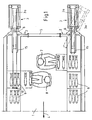
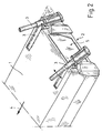
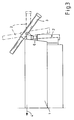
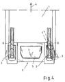
- FIGS. 1 to 4 show the installation of two 120mm mortar weapon systems (3) at the rear (2) of a mission module or at the rear of the vehicle (1).
- the vehicle moves forward in the direction of travel (4).
- By attaching the weapons (3) at the rear of the rear exit (5) is guaranteed.
- a complete redundancy of all weapon functions (loading, straightening, shooting) is given.
- Each Wafenstrom (3) is mounted by means of a side-facing pivot (6) at the rear (2) of the vehicle.
- the weapon is loaded in index position with 0 ° side and 0 ° height. Before each shot, the weapon is directed to a shooting position. After shooting is directed back to the loading position, the weapon barrel (3a) is pivoted into the loading trough (15) in the vehicle roof.
- the weapon is loaded by the loading flap (14) ( FIG. 7 ) into the muzzle according to the muzzle loading principle.
- the mortar tube is directed to different heights.
- the right tube is out in side out of the index position.
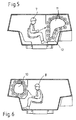
- FIGS. 6 and 7 the automated ammunition flow and the arrangement of two loaders (7, 8) are shown, which perform the preparation of ammunition (9).
- the exemplified asymmetric arrangement of the ammunition flow each provides a magazine (10, 11) for each loader (7, 8).
- the operation of two symmetrically arranged magazines by a loader with more time then would be possible.
- Preparing the ammunition which consists at least of the removal of propellants from the tailpipe of the ammunition and possibly also the detonator setting, which alternatively can also be done inductively and remotely, requires a suitably adapted and upright seating position of the loader in the vehicle.
- FIG. 5 In the direction of travel (4) left magazine (11) with associated loader (7) shown.
- the magazine (11) is positioned with respect to the vehicle center and longitudinal axis so that the seating position allows the loader (7) ergonomic operation of the magazine (11).
- FIG. 6 is the second right magazine (10) with an associated loader (8) under the same boundary conditions as the left magazine shown.
- this magazine allows a through-loading tube (13) pushing through the ammunition by a loading flap (14) in the barrel (3a).
- the ammunition is pushed directly through a corresponding loading flap (14) in the barrel (3a).
- the arrangement of the two magazines is also reversible possible depending on the space required for other installations.
- the arrangement and the size of the two magazines (10, 11) together with loaders is chosen in relation to the vehicle housing so that a passage to the rear through the rear exit (2) and vice versa is ensured.
- the storage of ammunition for example, most easily horizontally based on their main direction in electrically driven tape magazines.
- To load the ammunition from the magazines in the respective gun barrel piecing (16) are used, which are performed, for example, as a chain piecing.
- the supply of ammunition by piecing (16), the transport of ammunition in the automated magazines (10, 11), the alignment of the two weapons in height and side and possibly the firing is controlled by a system computer (not shown).
- the loaders only prepare the ammunition for the shoot.
- the Aufmunitionieren the magazines (10, 11) with ammunitions that can be accommodated occasionally on other magazines (12) in the vehicle, or from outside the vehicle is within the scope of loaders.
Landscapes
- Engineering & Computer Science (AREA)
- General Engineering & Computer Science (AREA)
- Aiming, Guidance, Guns With A Light Source, Armor, Camouflage, And Targets (AREA)
- Control Of Vehicles With Linear Motors And Vehicles That Are Magnetically Levitated (AREA)
- Fittings On The Vehicle Exterior For Carrying Loads, And Devices For Holding Or Mounting Articles (AREA)
- Refuge Islands, Traffic Blockers, Or Guard Fence (AREA)
- Body Structure For Vehicles (AREA)
Abstract
Description
Die Erfindung bezieht sich auf ein gepanzertes Fahrzeug nach den im Oberbegriff des Patentanspruchs 1 angegebenen Merkmale.The invention relates to an armored vehicle according to the features specified in the preamble of
Ein derartiges Fahrzeug setzt sich aus den üblichen Teilen wie Antriebsmotor, Getrieben, Radsätzen oder Kettenlaufwerk, einem Besatzungsraum und einem Gehäuse, das alle Ein- und Anbauten aufnimmt, zusammen. Insbesondere bei einem Schützenkampffahrzeug werden mit dem Fahrzeug mehrere Soldaten transportiert, die schnell über einen Heckausstieg aussteigen und aufsitzen können. Bei einem anderen Fahrzeugtyp, dem gepanzerten Transport-Kraftfahrzeug, abgekürzt GTK, wird das Fahrzeug in Module eingeteilt und ein so genanntes Missionsmodul austauschbar auf dem Chassis untergebracht. Verschiedene Bewaffnungen und Ausrüstungen können dann als Modul austauschbar auf dem Fahrzeug wechselweise mitgeführt werden.Such a vehicle is composed of the usual parts such as drive motor, gearboxes, wheelsets or chain drive, a crew room and a housing that receives all inputs and attachments together. In particular, in a rifle fighting vehicle several soldiers are transported by the vehicle, which can quickly get out and sit on a rear exit. In another type of vehicle, the armored transport vehicle, abbreviated GTK, the vehicle is divided into modules and housed a so-called mission module replaceable on the chassis. Various armaments and equipment can then be carried alternately as a module interchangeably on the vehicle.
Nach dem Stand der Technik sind verschiedene Vorschläge zum Aufbau von Fahrzeugen mit Mörserbewaffnung, bei denen der Waffenbetrieb unter Panzerschutz für die Besatzung erfolgt.According to the prior art are various proposals for the construction of vehicles with mortar armament, in which the operation of weapons under armored protection for the crew.
In einer Firmenschrift der Fa. MaK System Gesellschaft vom März 1999 mit dem Titel "Panzermörser 120mm le Ivb Wiesel 2" wird ein Kettenfahrzeug Typ Wiesel 2 gezeigt, bei dem eine Mörserwaffe mittig vom Fahrzeug am Heck eingebaut ist. Der Ein- und Ausstieg der Soldaten erfolgt hier durch Dachluken. (
In einer Firmenschrift der Fa. Bofors Weapon Systems,
In einer Firmenschrift der Fa. Patria Hägglunds Oy, Finnland, zu einem Mörser-Turmsystem AMOS (AMOS = Advanced Mortar System) wird eine Doppelmörserwaffe in einer gemeinsamen Waffenwiege gezeigt, die als Hinterladerwaffe in einem Turm am Fahrzeug eingebaut ist. Diese bekannten Doppelrohr-Mörserwaffen weisen zum Beispiel folgenden Nachteil auf. Bei der Hinterlader-Mörserwaffe als Turmlösung ist ein größerer Integrationsaufwand gegenüber einer Vorderlader-Mörserwaffe erforderlich.In a company publication of the company Patria Hägglunds Oy, Finland, to a mortar tower system AMOS (AMOS = Advanced Mortar System) a double mortar weapon in a common weapon cradle is shown, which is installed as a breech loader in a tower on the vehicle. These known double-tube mortar weapons have, for example, the following disadvantage. The backhoe mortar weapon as a tower solution requires a greater integration effort than a muzzleloader muzzle weapon.
Die weitere bekannte Lösung (Bofors) mit Doppelrohr-Vorderlader hat eine Waffenwiege als Lagerung für beide Waffenrohre, so dass keine Redundanz bei dem Richtantrieb besteht und die Rohre nicht unabhängig voneinander gerichtet werden können. Ebenfalls ist die Doppelanlage mittig am Fahrzeugheck realisiert, so dass ein Heckausstieg bei gegeben Maßen nicht realisierbar ist.The other known solution (Bofors) with double-tube muzzle loader has a weapon cradle as storage for both weapons tubes, so that there is no redundancy in the directional drive and the pipes can not be addressed independently. Also, the double system is realized centrally on the rear of the vehicle, so that a rear exit for given dimensions is not feasible.
Aus der
Die
Die
Mit der
Aufgabe der Erfindung ist es, zwei Mörserwaffen, vorzugsweise 120 mm redundant in ein bekanntes Fahrzeug zu integrieren. Dabei sollen der Heckausstieg des Fahrzeugs nicht beeinträchtigt werden, Vorderlader-Mörser zum Einsatz kommen und der gesamte Betrieb der Mörserwaffen unter Panzerschutz für die Besatzung erfolgen.The object of the invention is to integrate two mortar weapons, preferably 120 mm redundant in a known vehicle. The rear exit of the vehicle should not be affected, muzzleloader mortars are used and the entire operation of the mortar weapons under armored protection for the crew done.
Diese Aufgabe wird erfindungsgemäß durch die Merkmale des Anspruchs 1 gelöst. Vorteilhafte Ausgestaltungen der Erfindung gehen aus den Merkmalen der Unteransprüche hervor.This object is achieved by the features of
Der Erfindung liegt die Erkenntnis zugrunde, dass am Fahrzeugheck bzw. am heckseitigen Ende des Missionsmoduls, welches auf dem Fahrzeug eingebaut ist, an beiden Seiten links und rechts am Heck jeweils eine Pivot gelagerte vorzugsweise 120mm-Mörserwaffe mit einer jeweiligen Rücklaufeinrichtung angebaut sind. Beide Mörserwaffen haben jeweils eine Richtanlage, die über eine Steuerung und Rechneranlage koordiniert und angesteuert wird, so daß zum Beispiel beide Waffen das gleiche Ziel bekämpfen können. Bei Bedarf können die Waffen auch so gerichtet werden, dass eine gleichzeitige Detonation im Zielgebiet mit nacheinander und parallel verschossenen Granaten erreicht wird, womit die Feuerwirkung erheblich erhöht wird. Für diese Betriebsweise werden mehrere Munitionen für jede Waffe in einem zugeordneten automatisierten Magazin vorgehalten.The invention is based on the knowledge that at the rear of the vehicle or at the rear end of the mission module, which is installed on the vehicle, on both sides left and right at the rear of each pivot mounted preferably 120mm mortar weapon are mounted with a respective return device. Both mortars each have a straightening system, which is coordinated and controlled by a controller and computer system, so that, for example, both weapons can fight the same goal. If necessary, the weapons can also be aimed so that a simultaneous detonation in the target area with successive and parallel fired shells is achieved, whereby the fire effect is significantly increased. For this mode of operation, multiple ammunitions for each weapon are held in an associated automated magazine.
Die Vorteile der Erfindung liegen in der höheren Feuerkraft mit zwei Waffen gegenüber einer Waffe am Fahrzeug und der Redundanz der 2-Waffen-Ausführung, da auch bei Ausfall einer Waffe die Kampfkraft erhalten bleibt. Durch die Anbringung am Heck mittels Pivot-Lagerung werden nur geringe Änderungen beim Anbau der Waffe an einem Basisfahrzeug erforderlich. Vor allem kann der Heckausstieg unverändert für die Besatzung (7,8) oder sonstige Funktionen beibehalten werden, da die Waffen links und rechts vom Heckausstieg angebaut sind. Vorteilhaft ist auch, daß jede einzelne Waffe lieferbar vorhanden ist und nicht für den vorliegenden Zweck umgebaut oder entwickelt werden muss. Durch das Vorderladerprinzip des Mörsers gibt es keine Schussgasbelastung für die Bediener und Besatzung im Gegensatz zur Verwendung einer Mörserwaffe mit Verschluß und Hinterladung. Durch den automatisierten Munitionsfluss mittels automatisiertem Magazin wird eine Erhöhung der Schussfolge erreicht die über derjenigen mit manueller Bedienung liegt. Weitere Vorteile ergeben sich aus den Unteransprüchen.The advantages of the invention are the higher firepower with two weapons against a weapon on the vehicle and the redundancy of the 2-weapon design, as well as in case of failure of a weapon, the combat power is maintained. Attachment to the rear using pivot bearings requires only minor modifications to the weapon on a base vehicle. Above all, the rear exit can be kept unchanged for the crew (7,8) or other functions, since the weapons are attached to the left and right of the rear exit. It is also advantageous that each weapon is available available and does not need to be rebuilt or developed for the purpose. Due to the muzzleload's muzzleloader principle, there is no shotgun load for the operators and crew as opposed to using a mortar weapon with shutter and underload. The automated ammunition flow through the automated magazine increases the firing rate above that of manual operation. Further advantages emerge from the subclaims.
Ausführungsbeispiele der Erfindung sind in den Zeichnungen schematisch dargestellt und werden im folgenden näher beschrieben. Es zeigen:
- Figur 1:
- Eine Teil-Draufsicht im Schnitt des Fahrzeuges mit Waffenanlage
- Figur 2:
- die Ansicht der
Figur 1 - Figur 3:
- eine Seitenansicht des Fahrzeugs gemäß
Figur 1 - Figur 4:
- eine rückwärtige Ansicht des Fahrzeugs gemäß
Figur 1 - Figur 5:
- einen Fahrzeug-Querschnitt mit Detail Ladeschütze und Magazin links
- Figur 6:
- einen Fahrzeug-Querschnitt mit Ladeschütze und Magazin rechts
- Figur 7:
- eine Teil-Draufsicht des Fahrzeuges im Schnitt mit Ladeschützen links und rechts
- FIG. 1:
- A partial top view in section of the vehicle with weapon system
- FIG. 2:
- the view of
FIG. 1 in a perspective - FIG. 3:
- a side view of the vehicle according to
FIG. 1 - FIG. 4:
- a rear view of the vehicle according to
FIG. 1 - FIG. 5:
- a vehicle cross section with detail loader and magazine left
- FIG. 6:
- a vehicle cross section with loader and magazine right
- FIG. 7:
- a partial top view of the vehicle in section with loader left and right
Die
In den
In der
In
Die Zuführung der Munition durch Ansetzer (16), der Transport der Munition in den automatisierten Magazinen (10, 11), das Richten der beiden Waffen in Höhe und Seite und ggf. das Abfeuern wird von einem Systemrechner (nicht dargestellt) gesteuert. Die Ladeschützen bereiten lediglich die Munitionen vor für das Verschießen. Auch das Aufmunitionieren der Magazine (10, 11) mit Munitionen, die fallweise an weiteren Magazinen (12) im Fahrzeug untergebracht werden können, oder auch von außerhalb des Fahrzeuges liegt im Aufgabenbereich der Ladeschützen.The supply of ammunition by piecing (16), the transport of ammunition in the automated magazines (10, 11), the alignment of the two weapons in height and side and possibly the firing is controlled by a system computer (not shown). The loaders only prepare the ammunition for the shoot. The Aufmunitionieren the magazines (10, 11) with ammunitions that can be accommodated occasionally on other magazines (12) in the vehicle, or from outside the vehicle is within the scope of loaders.
- 11
- Fahrzeugvehicle
- 22
- HeckRear
- 33
- Mörser-WaffenanlageMortar weapon system
- 3a3a
- Waffenrohrbarrel
- 44
- Fahrtrichtungdirection of travel
- 55
- Heckausstiegrear exit
- 66
- Pivotpivot
- 77
- Ladeschützeloader
- 88th
- Ladeschützeloader
- 99
- Munitionammunition
- 1010
- Magazinmagazine
- 1111
- Magazinmagazine
- 1212
- weiteres Magazinanother magazine
- 1313
- DurchladerohrBy loading tube
- 1414
- Ladeklappetailboard
- 1515
- LademuldeBreech
- 1616
- Ansetzerrammer
Claims (12)
- Armoured vehicle (1) have a wheel drive or track drive and having a drive for forward movement as well as a vehicle structure for accommodation and installation of all the components for operation of the vehicle (1) including a vehicle crew (7, 8) and a rear exit (5) at the rear (2) of the vehicle (1), characterized in that a mortar weapon system (3), which can be operated and loaded with armour protection, and has weapon barrel (3a) and a pivoting carriage (6), direction drives and firing is arranged on each of the two sides at the rear (2) of the vehicle (1), to the left and right of the rear exit (5), is integrated in the vehicle and can be operated separately.
- Vehicle according to Claim 1, characterized in that both mortar weapon systems (3) can be aimed and coordinated in their firing response by means of a common control and computer device in the vehicle.
- Vehicle according to Claim 1 or 2, characterized in that the two mortar weapons (3) have a common weapon aiming system or each have a separate weapon aiming system, or have a combination of both.
- Vehicle according to one of Claims 1 to 3, characterized in that the mortar weapons (3) are designed so as to allow them to be fired in parallel or successively.
- Vehicle according to one of Claims 1 to 4, characterized in that an automated magazine (10, 11) is installed for each mortar weapon (3), storing a plurality of munitions (9).
- Vehicle according to Claim 5, characterized in that at least one of the two automated magazines (10, 11) allows manual adjustment of the munitions (9) contained in it.
- Vehicle according to one of Claims 1 to 6, characterized in that the mortar weapons (3) operate on the muzzle-loading principle.
- Vehicle according to one of Claims 1 to 7, characterized in that the magazines (10, 11) are arranged such that it is possible for loaders (7, 8) to pass through the rear exit (5) and to manually adjust the munition (9).
- Vehicle according to one of Claims 1 to 8, characterized in that the magazines (10, 11) are positioned with respect to the vehicle centre axis and longitudinal axis such that the seat position of the loader (7, 8) allows the magazines (10, 11) to be operated ergonomically.
- Vehicle according to one of Claims 1 to 9, characterized in that a through-loading tube (13) is installed for arrangement of the magazines (10, 11) in the vehicle (1).
- Vehicle according to one of Claims 1 to 10, characterized in that the magazines (10, 11) which are used are in the form electrically driven bolt magazines.
- Apparatus according to one of Claims 1 to 11, characterized in that the munition is inserted into the respective weapon barrel by means of chain feeds (16).
Applications Claiming Priority (2)
| Application Number | Priority Date | Filing Date | Title |
|---|---|---|---|
| DE10133144A DE10133144A1 (en) | 2001-07-07 | 2001-07-07 | Armored vehicle |
| DE10133144 | 2001-07-07 |
Publications (3)
| Publication Number | Publication Date |
|---|---|
| EP1273869A2 EP1273869A2 (en) | 2003-01-08 |
| EP1273869A3 EP1273869A3 (en) | 2004-06-09 |
| EP1273869B1 true EP1273869B1 (en) | 2008-02-20 |
Family
ID=7691068
Family Applications (1)
| Application Number | Title | Priority Date | Filing Date |
|---|---|---|---|
| EP02010800A Expired - Lifetime EP1273869B1 (en) | 2001-07-07 | 2002-05-15 | Armoured vehicle |
Country Status (5)
| Country | Link |
|---|---|
| EP (1) | EP1273869B1 (en) |
| AT (1) | ATE386918T1 (en) |
| DE (2) | DE10133144A1 (en) |
| DK (1) | DK1273869T3 (en) |
| ES (1) | ES2301586T3 (en) |
Families Citing this family (3)
| Publication number | Priority date | Publication date | Assignee | Title |
|---|---|---|---|---|
| DE10204299B4 (en) * | 2002-02-02 | 2004-03-11 | Rheinmetall Landsysteme Gmbh | Forced removal mechanism for weapons, equipment or crew equipment in an armored transport vehicle |
| DE102012001172A1 (en) * | 2012-01-24 | 2013-07-25 | Rheinmetall Waffe Munition Gmbh | Weapon such as nozzle mortar attached to vehicle, has weapon pipe that is driven by elevation drive element into specific position such that ammunition is pushed from bottom region to top region into open weapon pipe |
| FR3002030B1 (en) | 2013-02-12 | 2017-08-11 | Nexter Systems | LIGHT ARMY SYSTEM |
Family Cites Families (13)
| Publication number | Priority date | Publication date | Assignee | Title |
|---|---|---|---|---|
| FR1099576A (en) * | 1954-02-16 | 1955-09-07 | Armored combat vehicle | |
| FR1602851A (en) * | 1954-03-16 | 1971-02-08 | ||
| GB1294006A (en) * | 1969-09-04 | 1972-10-25 | Aerospatiale | Guided missile firing turret |
| FR2301797A1 (en) * | 1975-02-18 | 1976-09-17 | Creusot Loire | MISSILES LAUNCH FACILITY |
| US4326446A (en) * | 1979-11-19 | 1982-04-27 | The United States Of America As Represented By The Secretary Of The Army | Linkage of actuating system for elevating gun mount |
| DE3121963A1 (en) * | 1981-06-03 | 1982-12-23 | Rheinmetall GmbH, 4000 Düsseldorf | MOERSER WITH A RETURN RETURN DEVICE INTEGRATED IN A PIPE WEIGHER |
| DE3440467A1 (en) * | 1984-11-06 | 1986-05-07 | Diehl GmbH & Co, 8500 Nürnberg | WEAPON SYSTEM WITH TUBE ARMON IN TANK VEHICLE |
| DE3703952A1 (en) * | 1987-02-10 | 1988-08-18 | Krupp Gmbh | Control and monitoring panel for an armoured vehicle (tank) |
| AT408690B (en) * | 1996-06-20 | 2002-02-25 | Dynamit Nobel Graz Gmbh | STEALFIRE PROTECTION, ESPECIALLY GRENADE LAUNCHERS |
| ATE185895T1 (en) * | 1996-08-20 | 1999-11-15 | Wegmann & Co Gmbh | COMBAT VEHICLE WITH DIESEL-ELECTRIC DRIVE AND REAR HATCH |
| DE19633904C2 (en) * | 1996-08-22 | 2000-01-20 | Rheinmetall W & M Gmbh | Muzzle-loading weapon |
| DE19713192C2 (en) * | 1997-03-27 | 2000-02-24 | Rheinmetall Ind Ag | Carrier vehicle for a barrel weapon with a support device |
| DE19927646C5 (en) | 1999-06-17 | 2006-05-11 | Wieland-Werke Ag | Use of a tin-rich copper-tin-iron alloy |
-
2001
- 2001-07-07 DE DE10133144A patent/DE10133144A1/en not_active Withdrawn
-
2002
- 2002-05-15 EP EP02010800A patent/EP1273869B1/en not_active Expired - Lifetime
- 2002-05-15 ES ES02010800T patent/ES2301586T3/en not_active Expired - Lifetime
- 2002-05-15 DE DE50211720T patent/DE50211720D1/en not_active Expired - Lifetime
- 2002-05-15 AT AT02010800T patent/ATE386918T1/en active
- 2002-05-15 DK DK02010800T patent/DK1273869T3/en active
Also Published As
| Publication number | Publication date |
|---|---|
| ES2301586T3 (en) | 2008-07-01 |
| EP1273869A3 (en) | 2004-06-09 |
| ATE386918T1 (en) | 2008-03-15 |
| DE10133144A1 (en) | 2003-01-30 |
| DK1273869T3 (en) | 2008-06-02 |
| DE50211720D1 (en) | 2008-04-03 |
| EP1273869A2 (en) | 2003-01-08 |
Similar Documents
| Publication | Publication Date | Title |
|---|---|---|
| EP1061323B1 (en) | Armoured vehicle for the transport of soldiers | |
| EP1717541B2 (en) | Launcher | |
| DE60210182T2 (en) | Two-armed tower for a military combat vehicle | |
| EP0141900B1 (en) | Automatic loading device for an armoured vehicle with rotatable armoured turret | |
| CH659318A5 (en) | LOCKING DEVICE FOR LOCKING SELF-DRIVEN PIPELINE BULLETS FROM AIRCRAFT. | |
| DE10258263B4 (en) | firing module | |
| EP1898172B1 (en) | Large caliber naval gun | |
| EP2710323B1 (en) | Ordnance and military vehicle | |
| DE102011050685B4 (en) | Weapon, in particular mortar, straightening device and method for operating a weapon | |
| EP1273869B1 (en) | Armoured vehicle | |
| EP0906553B1 (en) | High angle fire gun, in particular grenade launching weapon | |
| DE69005089T2 (en) | Turret for light tanks, equipped with a weapon attached to the side. | |
| DE2257679C3 (en) | Loading aid for tank cannons | |
| DE2019144C1 (en) | Armoured fighting vehicle with turret - has protected crew chamber in front of ammunition chamber below turret | |
| EP0844455B1 (en) | Mounting of a gun in an armoured turret | |
| DE19717734A1 (en) | Combat vehicle | |
| DE20122721U1 (en) | Armored vehicle has mortar weapon system, useable and loadable under armor protection, with weapon pipe and pivot carriage, directional drive and firing is arranged at tail of vehicle | |
| DE3042675A1 (en) | Armoured vehicle gun loading equipment - has rotary plate supporting rounds upright parallel to axis of rotation | |
| DE10160207B4 (en) | ammunition magazine | |
| DE102015008796A1 (en) | Weapon with a tube bundle | |
| DE2852699C1 (en) | Device for the supply of ammunition from a magazine located below a rotatable platform to a crest gun mounted on the platform | |
| DE102021001804A1 (en) | ARMORED HOWITZER IN 203 MM CALIBER | |
| DE1959548A1 (en) | Armored vehicle, especially Panzerjaeger | |
| DE102022103329A1 (en) | gun turret | |
| DE102019006566A1 (en) | CANOPY BIT, ESPECIALLY IN THE 203 MM CALIBER |
Legal Events
| Date | Code | Title | Description |
|---|---|---|---|
| PUAI | Public reference made under article 153(3) epc to a published international application that has entered the european phase |
Free format text: ORIGINAL CODE: 0009012 |
|
| AK | Designated contracting states |
Kind code of ref document: A2 Designated state(s): AT BE CH CY DE DK ES FI FR GB GR IE IT LI LU MC NL PT SE TR |
|
| AX | Request for extension of the european patent |
Free format text: AL;LT;LV;MK;RO;SI |
|
| PUAL | Search report despatched |
Free format text: ORIGINAL CODE: 0009013 |
|
| AK | Designated contracting states |
Kind code of ref document: A3 Designated state(s): AT BE CH CY DE DK ES FI FR GB GR IE IT LI LU MC NL PT SE TR |
|
| AX | Request for extension of the european patent |
Extension state: AL LT LV MK RO SI |
|
| 17P | Request for examination filed |
Effective date: 20040429 |
|
| AKX | Designation fees paid |
Designated state(s): AT BE CH CY DE DK ES FI FR GB GR IE IT LI LU MC NL PT SE TR |
|
| RAP1 | Party data changed (applicant data changed or rights of an application transferred) |
Owner name: RHEINMETALL LANDSYSTEME GMBH |
|
| 17Q | First examination report despatched |
Effective date: 20061018 |
|
| GRAP | Despatch of communication of intention to grant a patent |
Free format text: ORIGINAL CODE: EPIDOSNIGR1 |
|
| GRAS | Grant fee paid |
Free format text: ORIGINAL CODE: EPIDOSNIGR3 |
|
| GRAA | (expected) grant |
Free format text: ORIGINAL CODE: 0009210 |
|
| AK | Designated contracting states |
Kind code of ref document: B1 Designated state(s): AT BE CH CY DE DK ES FI FR GB GR IE IT LI LU MC NL PT SE TR |
|
| REG | Reference to a national code |
Ref country code: GB Ref legal event code: FG4D Free format text: NOT ENGLISH |
|
| REG | Reference to a national code |
Ref country code: CH Ref legal event code: EP |
|
| REG | Reference to a national code |
Ref country code: IE Ref legal event code: FG4D Free format text: LANGUAGE OF EP DOCUMENT: GERMAN |
|
| REF | Corresponds to: |
Ref document number: 50211720 Country of ref document: DE Date of ref document: 20080403 Kind code of ref document: P |
|
| REG | Reference to a national code |
Ref country code: SE Ref legal event code: TRGR |
|
| GBT | Gb: translation of ep patent filed (gb section 77(6)(a)/1977) |
Effective date: 20080423 |
|
| REG | Reference to a national code |
Ref country code: DK Ref legal event code: T3 |
|
| REG | Reference to a national code |
Ref country code: CH Ref legal event code: NV Representative=s name: OK PAT AG PATENTE MARKEN LIZENZEN |
|
| REG | Reference to a national code |
Ref country code: ES Ref legal event code: FG2A Ref document number: 2301586 Country of ref document: ES Kind code of ref document: T3 |
|
| REG | Reference to a national code |
Ref country code: IE Ref legal event code: FD4D |
|
| ET | Fr: translation filed | ||
| PG25 | Lapsed in a contracting state [announced via postgrant information from national office to epo] |
Ref country code: IE Free format text: LAPSE BECAUSE OF FAILURE TO SUBMIT A TRANSLATION OF THE DESCRIPTION OR TO PAY THE FEE WITHIN THE PRESCRIBED TIME-LIMIT Effective date: 20080220 Ref country code: PT Free format text: LAPSE BECAUSE OF FAILURE TO SUBMIT A TRANSLATION OF THE DESCRIPTION OR TO PAY THE FEE WITHIN THE PRESCRIBED TIME-LIMIT Effective date: 20080721 |
|
| BERE | Be: lapsed |
Owner name: RHEINMETALL LANDSYSTEME G.M.B.H. Effective date: 20080531 |
|
| PLBE | No opposition filed within time limit |
Free format text: ORIGINAL CODE: 0009261 |
|
| STAA | Information on the status of an ep patent application or granted ep patent |
Free format text: STATUS: NO OPPOSITION FILED WITHIN TIME LIMIT |
|
| PG25 | Lapsed in a contracting state [announced via postgrant information from national office to epo] |
Ref country code: MC Free format text: LAPSE BECAUSE OF NON-PAYMENT OF DUE FEES Effective date: 20080531 |
|
| 26N | No opposition filed |
Effective date: 20081121 |
|
| PG25 | Lapsed in a contracting state [announced via postgrant information from national office to epo] |
Ref country code: BE Free format text: LAPSE BECAUSE OF NON-PAYMENT OF DUE FEES Effective date: 20080531 |
|
| PG25 | Lapsed in a contracting state [announced via postgrant information from national office to epo] |
Ref country code: CY Free format text: LAPSE BECAUSE OF FAILURE TO SUBMIT A TRANSLATION OF THE DESCRIPTION OR TO PAY THE FEE WITHIN THE PRESCRIBED TIME-LIMIT Effective date: 20080220 |
|
| PGFP | Annual fee paid to national office [announced via postgrant information from national office to epo] |
Ref country code: DK Payment date: 20090513 Year of fee payment: 8 Ref country code: NL Payment date: 20090527 Year of fee payment: 8 |
|
| PG25 | Lapsed in a contracting state [announced via postgrant information from national office to epo] |
Ref country code: LU Free format text: LAPSE BECAUSE OF NON-PAYMENT OF DUE FEES Effective date: 20080515 |
|
| PG25 | Lapsed in a contracting state [announced via postgrant information from national office to epo] |
Ref country code: GR Free format text: LAPSE BECAUSE OF FAILURE TO SUBMIT A TRANSLATION OF THE DESCRIPTION OR TO PAY THE FEE WITHIN THE PRESCRIBED TIME-LIMIT Effective date: 20080521 |
|
| REG | Reference to a national code |
Ref country code: NL Ref legal event code: V1 Effective date: 20101201 |
|
| REG | Reference to a national code |
Ref country code: DK Ref legal event code: EBP |
|
| PG25 | Lapsed in a contracting state [announced via postgrant information from national office to epo] |
Ref country code: NL Free format text: LAPSE BECAUSE OF NON-PAYMENT OF DUE FEES Effective date: 20101201 |
|
| PG25 | Lapsed in a contracting state [announced via postgrant information from national office to epo] |
Ref country code: DK Free format text: LAPSE BECAUSE OF NON-PAYMENT OF DUE FEES Effective date: 20100531 |
|
| PGFP | Annual fee paid to national office [announced via postgrant information from national office to epo] |
Ref country code: TR Payment date: 20140509 Year of fee payment: 13 |
|
| REG | Reference to a national code |
Ref country code: FR Ref legal event code: PLFP Year of fee payment: 14 |
|
| PGFP | Annual fee paid to national office [announced via postgrant information from national office to epo] |
Ref country code: FI Payment date: 20150812 Year of fee payment: 14 Ref country code: DE Payment date: 20150730 Year of fee payment: 14 Ref country code: CH Payment date: 20150819 Year of fee payment: 14 Ref country code: GB Payment date: 20150730 Year of fee payment: 14 Ref country code: ES Payment date: 20150728 Year of fee payment: 14 |
|
| PGFP | Annual fee paid to national office [announced via postgrant information from national office to epo] |
Ref country code: AT Payment date: 20150731 Year of fee payment: 14 Ref country code: FR Payment date: 20150730 Year of fee payment: 14 Ref country code: SE Payment date: 20150730 Year of fee payment: 14 |
|
| PGFP | Annual fee paid to national office [announced via postgrant information from national office to epo] |
Ref country code: IT Payment date: 20150730 Year of fee payment: 14 |
|
| REG | Reference to a national code |
Ref country code: DE Ref legal event code: R119 Ref document number: 50211720 Country of ref document: DE |
|
| REG | Reference to a national code |
Ref country code: CH Ref legal event code: PL |
|
| REG | Reference to a national code |
Ref country code: AT Ref legal event code: MM01 Ref document number: 386918 Country of ref document: AT Kind code of ref document: T Effective date: 20160515 |
|
| GBPC | Gb: european patent ceased through non-payment of renewal fee |
Effective date: 20160515 |
|
| PG25 | Lapsed in a contracting state [announced via postgrant information from national office to epo] |
Ref country code: CH Free format text: LAPSE BECAUSE OF NON-PAYMENT OF DUE FEES Effective date: 20160531 Ref country code: LI Free format text: LAPSE BECAUSE OF NON-PAYMENT OF DUE FEES Effective date: 20160531 Ref country code: FI Free format text: LAPSE BECAUSE OF NON-PAYMENT OF DUE FEES Effective date: 20160515 |
|
| PG25 | Lapsed in a contracting state [announced via postgrant information from national office to epo] |
Ref country code: AT Free format text: LAPSE BECAUSE OF NON-PAYMENT OF DUE FEES Effective date: 20160515 Ref country code: IT Free format text: LAPSE BECAUSE OF NON-PAYMENT OF DUE FEES Effective date: 20160515 Ref country code: SE Free format text: LAPSE BECAUSE OF NON-PAYMENT OF DUE FEES Effective date: 20160516 |
|
| REG | Reference to a national code |
Ref country code: FR Ref legal event code: ST Effective date: 20170131 |
|
| PG25 | Lapsed in a contracting state [announced via postgrant information from national office to epo] |
Ref country code: DE Free format text: LAPSE BECAUSE OF NON-PAYMENT OF DUE FEES Effective date: 20161201 Ref country code: FR Free format text: LAPSE BECAUSE OF NON-PAYMENT OF DUE FEES Effective date: 20160531 |
|
| PG25 | Lapsed in a contracting state [announced via postgrant information from national office to epo] |
Ref country code: GB Free format text: LAPSE BECAUSE OF NON-PAYMENT OF DUE FEES Effective date: 20160515 |
|
| PG25 | Lapsed in a contracting state [announced via postgrant information from national office to epo] |
Ref country code: ES Free format text: LAPSE BECAUSE OF NON-PAYMENT OF DUE FEES Effective date: 20160516 |
|
| REG | Reference to a national code |
Ref country code: ES Ref legal event code: FD2A Effective date: 20181203 |
|
| PG25 | Lapsed in a contracting state [announced via postgrant information from national office to epo] |
Ref country code: TR Free format text: LAPSE BECAUSE OF NON-PAYMENT OF DUE FEES Effective date: 20160515 |