EP1273869A2 - Armoured vehicle - Google Patents
Armoured vehicle Download PDFInfo
- Publication number
- EP1273869A2 EP1273869A2 EP02010800A EP02010800A EP1273869A2 EP 1273869 A2 EP1273869 A2 EP 1273869A2 EP 02010800 A EP02010800 A EP 02010800A EP 02010800 A EP02010800 A EP 02010800A EP 1273869 A2 EP1273869 A2 EP 1273869A2
- Authority
- EP
- European Patent Office
- Prior art keywords
- vehicle
- weapon
- mortar
- ammunition
- magazines
- Prior art date
- Legal status (The legal status is an assumption and is not a legal conclusion. Google has not performed a legal analysis and makes no representation as to the accuracy of the status listed.)
- Granted
Links
Images


Classifications
-
- F—MECHANICAL ENGINEERING; LIGHTING; HEATING; WEAPONS; BLASTING
- F41—WEAPONS
- F41A—FUNCTIONAL FEATURES OR DETAILS COMMON TO BOTH SMALLARMS AND ORDNANCE, e.g. CANNONS; MOUNTINGS FOR SMALLARMS OR ORDNANCE
- F41A23/00—Gun mountings, e.g. on vehicles; Disposition of guns on vehicles
- F41A23/34—Gun mountings, e.g. on vehicles; Disposition of guns on vehicles on wheeled or endless-track vehicles
-
- F—MECHANICAL ENGINEERING; LIGHTING; HEATING; WEAPONS; BLASTING
- F41—WEAPONS
- F41A—FUNCTIONAL FEATURES OR DETAILS COMMON TO BOTH SMALLARMS AND ORDNANCE, e.g. CANNONS; MOUNTINGS FOR SMALLARMS OR ORDNANCE
- F41A9/00—Feeding or loading of ammunition; Magazines; Guiding means for the extracting of cartridges
- F41A9/38—Loading arrangements, i.e. for bringing the ammunition into the firing position
- F41A9/45—Loading arrangements, i.e. for bringing the ammunition into the firing position the cartridge chamber or the barrel as a whole being tiltable or transversely slidable between a loading and a firing position
Definitions
- the invention relates to an armored vehicle according to the The preamble of claim 1 features specified.
- Such a vehicle consists of the usual parts such as Drive motor, gears, wheelsets or chain drive, one Crew room and a housing that contains all fittings and attachments takes up together.
- a rifle combat vehicle several soldiers are transported by vehicle, who quickly over get out of the rear exit and sit on it.
- Another one Vehicle type, the armored transport vehicle, abbreviated GTK the vehicle is divided into modules and a so-called Mission module interchangeably housed on the chassis. Different armaments and equipment can then be used as a module can be carried interchangeably on the vehicle.
- AMOS Advanced Mortar System
- the rear-loading mortar weapon as a turret solution is a larger one Integration effort compared to a muzzle-loading mortar weapon required.
- the other known solution (Bofors) with double-tube front loader has one Gun cradle as storage for both gun barrels, so that none There is redundancy in the directional drive and the pipes are not independent can be directed from each other.
- the double system is also Realized in the center of the rear of the vehicle, so that a rear exit is given Dimensions is not feasible.
- the object of the invention is two mortar weapons, preferably 120 mm to integrate redundantly in a known vehicle.
- the Rear exit of the vehicle is not affected, muzzle-loading mortar are used and the entire operation of the mortar weapons under armor protection for the crew.
- the invention is based on the knowledge that the rear of the vehicle or at the rear end of the mission module, which is on the vehicle a pivot is installed on both sides left and right at the rear stored preferably 120mm mortar weapon with a respective one Return device are attached.
- Both mortar weapons have one each Straightening system that coordinates and via a control and computer system is controlled so that, for example, both weapons the same target can fight. If necessary, the weapons can also be aimed in this way be that a simultaneous detonation in the target area with one after the other and grenades fired in parallel, with which the Fire effect is increased significantly. For this mode of operation multiple ammunition for each weapon in an associated automated Magazine held.
- the advantages of the invention lie in the higher firepower with two Weapons compared to a weapon on the vehicle and the redundancy of the 2-weapon version, because even if a weapon fails, the fighting power preserved.
- By attaching to the rear using pivot storage there are only minor changes in the attachment of the weapon to one Base vehicle required. Above all, the rear exit can remain unchanged for the crew (7,8) or other functions, because the weapons are attached to the left and right of the rear exit.
- every single weapon is available and not for the existing purpose must be converted or developed.
- the muzzle-loading principle of the mortar means there is no shot gas load for the Operator and crew as opposed to using a mortar weapon with lock and rear loading. Through the automated ammunition flow an automated magazine increases the firing order reached which is higher than that with manual operation. Additional advantages result from the subclaims.
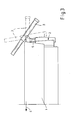
- FIGs 1 to 4 show the attachment of two 120mm mortar weapon systems (3) at the rear (2) of a mission module or at the rear of the Vehicle (1).
- the vehicle moves forward in the direction of travel (4).
- By attaching the weapons (3) to the rear the rear exit (5) is guaranteed.
- each Wafer system (3) is by means of a side-directional pivot (6) at the rear (2) of the vehicle.
- the weapon is loaded in the index position with 0 ° side and 0 ° height. Before each shot, the weapon is put in one Firing position aimed. After the shooting is back in the Loading position directed, the gun barrel (3a) in the loading trough (15) is pivoted in the vehicle roof.
- the weapon is loaded by the Loading flap (14) ( Figure 7) in the pipe mouth after the Muzzle-loading principle.
- the mortar tube is at different heights directed.
- the right tube is from the side Index position directed out.
- the magazine (11) is regarding the vehicle center and longitudinal axis positioned so that the seating position the loader (7) ergonomic operation of the magazine (11) allowed.
- the second right magazine (10) with an associated Loaders (8) under the same conditions as the left one Illustrated magazine.
- a through-loading tube (13) pushing the ammunition through a loading flap (14) into the Gun barrel (3a).
- the ammunition is directly through a corresponding loading flap (14) pushed into the gun barrel (3a).
- the arrangement of the two magazines is also possible interchanged depending on Space required for further installations.
- the arrangement and size of the two magazines (10, 11) including loaders is related to that Vehicle housing chosen so that a passage to the rear through the Rear exit (2) and vice versa is ensured.
- the storage of the The easiest way to do ammunition, for example, is horizontally in relation to yours Main direction in electrically driven belt magazines.
- piecing (16) used which are designed, for example, as chain attachers.
Abstract
Description
Die Erfindung bezieht sich auf ein gepanzertes Fahrzeug nach den im
Oberbegriff des Patentanspruchs 1 angegebenen Merkmalen.The invention relates to an armored vehicle according to the
The preamble of
Ein derartiges Fahrzeug setzt sich aus den üblichen Teilen wie Antriebsmotor, Getrieben, Radsätzen oder Kettenlaufwerk, einem Besatzungsraum und einem Gehäuse, das alle Ein- und Anbauten aufnimmt, zusammen. Insbesondere bei einem Schützenkampffahrzeug werden mit dem Fahrzeug mehrere Soldaten transportiert, die schnell über einen Heckausstieg aussteigen und aufsitzen können. Bei einem anderen Fahrzeugtyp, dem gepanzerten Transport-Kraftfahrzeug, abgekürzt GTK, wird das Fahrzeug in Module eingeteilt und ein sogenanntes Missionsmodul austauschbar auf dem Chassis untergebracht. Verschiedene Bewaffnungen und Ausrüstungen können dann als Modul austauschbar auf dem Fahrzeug wechselweise mitgeführt werden.Such a vehicle consists of the usual parts such as Drive motor, gears, wheelsets or chain drive, one Crew room and a housing that contains all fittings and attachments takes up together. Especially in a rifle combat vehicle several soldiers are transported by vehicle, who quickly over get out of the rear exit and sit on it. Another one Vehicle type, the armored transport vehicle, abbreviated GTK, the vehicle is divided into modules and a so-called Mission module interchangeably housed on the chassis. Different armaments and equipment can then be used as a module can be carried interchangeably on the vehicle.
Nach dem Stand der Technik sind verschiedene Vorschläge zum Aufbau von Fahrzeugen mit Mörserbewaffnung, bei denen der Waffenbetrieb unter Panzerschutz für die Besatzung erfolgt.According to the state of the art, there are various proposals for the structure of vehicles with mortar armament, in which the weapons operation under Armor protection for the crew took place.
In einer Firmenschrift der Fa. MaK System Gesellschaft vom März 1999 mit dem Titel "Panzermörser 120mm le Ivb Wiesel 2" wird ein Kettenfahrzeug Typ Wiesel 2 gezeigt, bei dem eine Mörserwaffe mittig vom Fahrzeug am Heck eingebaut ist. Der Ein- und Ausstieg der Soldaten erfolgt hier durch Dachluken.In a company publication of MaK System Gesellschaft from March 1999 with the track "tank mortar 120mm le Ivb Wiesel 2" becomes a tracked vehicle Type Wiesel 2 shown, in which a mortar weapon is centered on the vehicle at Rear is installed. The soldiers get on and off here Skylights.
In einer Firmenschrift der Fa. Bofors Weapon Systems, Schweden, Nr. PB-04-486-E-I, wird ein Doppelrohr-Vorderladermörser am Heck eines Kettenfahrzeugs gezeigt, bei dem die beiden Waffen in geringem Abstand voneinander zusammengebaut sind. In a company publication of Bofors Weapon Systems, Sweden, No. PB-04-486-E-I, becomes a double-pipe front-loading mortar at the rear of a Tracked vehicle shown, with the two weapons at a short distance are assembled from each other.
In einer Firmenschrift der Fa. Patria Hägglunds Oy, Finnland, zu einem Mörser-Turmsystem AMOS (AMOS = Advanced Mortar System) wird eine Doppelmörserwaffe in einer gemeinsamen Waffenwiege gezeigt, die als Hinterladerwaffe in einem Turm am Fahrzeug eingebaut ist.In a company publication of Patria Hägglunds Oy, Finland, for one Mortar tower system AMOS (AMOS = Advanced Mortar System) becomes one Double mortar weapon shown in a common weapon cradle, which as Breech loading weapon is installed in a turret on the vehicle.
Diese bekannten Doppelrohr-Mörserwaffen weisen zum Beispiel folgende Nachteile auf.These known double-barrel mortar weapons have, for example, the following Disadvantages.
Bei der Hinterlader-Mörserwaffe als Turmlösung ist ein grösserer Integrationsaufwand gegenüber einer Vorderlader-Mörserwaffe erforderlich.The rear-loading mortar weapon as a turret solution is a larger one Integration effort compared to a muzzle-loading mortar weapon required.
Die weitere bekannte Lösung (Bofors) mit Doppelrohr-Vorderlader hat eine Waffenwiege als Lagerung für beide Waffenrohre, so dass keine Redundanz bei dem Richtantrieb besteht und die Rohre nicht unabhängig voneinander gerichtet werden können. Ebenfalls ist die Doppelanlage mittig am Fahrzeugheck realisiert, so dass ein Heckausstieg bei gegeben Maßen nicht realisierbar ist.The other known solution (Bofors) with double-tube front loader has one Gun cradle as storage for both gun barrels, so that none There is redundancy in the directional drive and the pipes are not independent can be directed from each other. The double system is also Realized in the center of the rear of the vehicle, so that a rear exit is given Dimensions is not feasible.
Aus der DE 19927656A1 ist ein gepanzertes gattungsgemäßes Transportkraftfahrzeug bekannt, welches jedoch mit einem unbemannten Schartenturm einschliesslich Lafette und Bordmaschinenwaffe als Bewaffnung ausgerüstet ist, der von der Besatzung aus dem Fahrzeuginneren fernbedient wird.From DE 19927656A1 is an armored generic Transport vehicle known, but with an unmanned Chart tower including gun carriage and on-board machine gun as Armament is equipped by the crew from the The vehicle interior is operated remotely.
Aufgabe der Erfindung ist es, zwei Mörserwaffen, vorzugsweise 120 mm redundant in ein bekanntes Fahrzeug zu integrieren. Dabei sollen der Heckausstieg des Fahrzeugs nicht beeinträchtigt werden, Vorderlader-Mörser zum Einsatz kommen und der gesamte Betrieb der Mörserwaffen unter Panzerschutz für die Besatzung erfolgen.The object of the invention is two mortar weapons, preferably 120 mm to integrate redundantly in a known vehicle. The Rear exit of the vehicle is not affected, muzzle-loading mortar are used and the entire operation of the mortar weapons under armor protection for the crew.
Diese Aufgabe wird erfindungsgemäß durch die kennzeichnenden
Merkmale des Anspruchs 1 gelöst. Vorteilhafte Ausgestaltungen der
Erfindung gehen aus den Merkmalen der Unteransprüche hervor.This object is achieved by the characterizing
Features of
Der Erfindung liegt die Erkenntnis zugrunde, dass am Fahrzeugheck bzw. am heckseitigen Ende des Missionsmoduls, welches auf dem Fahrzeug eingebaut ist, an beiden Seiten links und rechts am Heck jeweils eine Pivot gelagerte vorzugsweise 120mm-Mörserwaffe mit einer jeweiligen Rücklaufeinrichtung angebaut sind. Beide Mörserwaffen haben jeweils eine Richtanlage, die über eine Steuerung und Rechneranlage koordiniert und angesteuert wird, so daß zum Beispiel beide Waffen das gleiche Ziel bekämpfen können. Bei Bedarf können die Waffen auch so gerichtet werden, dass eine gleichzeitige Detonation im Zielgebiet mit nacheinander und parallel verschossenen Granaten erreicht wird, womit die Feuerwirkung erheblich erhöht wird. Für diese Betriebsweise werden mehrere Munitionen für jede Waffe in einem zugeordneten automatisierten Magazin vorgehalten.The invention is based on the knowledge that the rear of the vehicle or at the rear end of the mission module, which is on the vehicle a pivot is installed on both sides left and right at the rear stored preferably 120mm mortar weapon with a respective one Return device are attached. Both mortar weapons have one each Straightening system that coordinates and via a control and computer system is controlled so that, for example, both weapons the same target can fight. If necessary, the weapons can also be aimed in this way be that a simultaneous detonation in the target area with one after the other and grenades fired in parallel, with which the Fire effect is increased significantly. For this mode of operation multiple ammunition for each weapon in an associated automated Magazine held.
Die Vorteile der Erfindung liegen in der höheren Feuerkraft mit zwei Waffen gegenüber einer Waffe am Fahrzeug und der Redundanz der 2-Waffen-Ausführung, da auch bei Ausfall einer Waffe die Kampfkraft erhalten bleibt. Durch die Anbringung am Heck mittels Pivot-Lagerung werden nur geringe Änderungen beim Anbau der Waffe an einem Basisfahrzeug erforderlich. Vor allem kann der Heckausstieg unverändert für die Besatzung (7,8) oder sonstige Funktionen beibehalten werden, da die Waffen links und rechts vom Heckausstieg angebaut sind. Vorteilhaft ist auch, daß jede einzelne Waffe lieferbar vorhanden ist und nicht für den vorliegenden Zweck umgebaut oder entwickelt werden muss. Durch das Vorderladerprinzip des Mörsers gibt es keine Schussgasbelastung für die Bediener und Besatzung im Gegensatz zur Verwendung einer Mörserwaffe mit Verschluß und Hinterladung. Durch den automatisierten Munitionsfluss mittels automatisiertem Magazin wird eine Erhöhung der Schussfolge erreicht die über derjenigen mit manueller Bedienung liegt. Weitere Vorteile ergeben sich aus den Unteransprüchen.The advantages of the invention lie in the higher firepower with two Weapons compared to a weapon on the vehicle and the redundancy of the 2-weapon version, because even if a weapon fails, the fighting power preserved. By attaching to the rear using pivot storage there are only minor changes in the attachment of the weapon to one Base vehicle required. Above all, the rear exit can remain unchanged for the crew (7,8) or other functions, because the weapons are attached to the left and right of the rear exit. Advantageous is also that every single weapon is available and not for the existing purpose must be converted or developed. By the The muzzle-loading principle of the mortar means there is no shot gas load for the Operator and crew as opposed to using a mortar weapon with lock and rear loading. Through the automated ammunition flow an automated magazine increases the firing order reached which is higher than that with manual operation. Additional advantages result from the subclaims.
Ausführungsbeispiele der Erfindung sind in den Zeichnungen schematisch dargestellt und werden im folgenden näher beschrieben. Es zeigen:
- Figur 1:
- Eine Teil-Draufsicht im Schnitt des Fahrzeuges mit Waffenanlage
- Figur 2:
- die Ansicht der
Figur 1 in einer Perspektive - Figur 3:
- eine Seitenansicht des Fahrzeugs gemäß
Figur 1 - Figur 4:
- eine rückwärtige Ansicht des Fahrzeugs gemäß
Figur 1 - Figur 5:
- einen Fahrzeug-Querschnitt mit Detail Ladeschütze und Magazin links
- Figur 6:
- einen Fahrzeug-Querschnitt mit Ladeschütze und Magazin rechts
- Figur 7:
- eine Teil-Draufsicht des Fahrzeuges im Schnitt mit Ladeschützen links und rechts
- Figure 1:
- A partial top view in section of the vehicle with weapon system
- Figure 2:
- the view of Figure 1 in a perspective
- Figure 3:
- 2 shows a side view of the vehicle according to FIG. 1
- Figure 4:
- 3 shows a rear view of the vehicle according to FIG. 1
- Figure 5:
- a vehicle cross-section with the detail of the loader and magazine on the left
- Figure 6:
- a vehicle cross section with loaders and magazine on the right
- Figure 7:
- a partial top view of the vehicle in section with loaders left and right
Die Figuren 1 bis 4 zeigen den Anbau von zwei 120mm Mörser-Waffenanlagen (3) am Heck (2) eines Missionsmoduls bzw. am Heck des Fahrzeugs (1). Das Fahrzeug bewegt sich in Fahrtrichtung (4) nach vorn. Durch die Anbringung der Waffen (3) am Heck ist der Heckausstieg (5) gewährleistet. Gleichzeitig ist eine vollständige Redundanz aller Waffenfunktionen (Laden, Richten, Schießen) gegeben. Jede Wafenanlage (3) ist mittels eines seitenrichtbaren Pivots (6) am Heck (2) des Fahrzeugs gelagert. Das Laden der Waffe erfolgt in Indexposition mit 0° Seite und 0° Höhe. Vor jedem Schuß wird die Waffe in eine Schießposition gerichtet. Nach dem Schießen wird wieder in die Ladeposition gerichtet, wobei das Waffenrohr (3a) in die Lademulde (15) im Fahrzeugdach geschwenkt wird. Das Laden der Waffe erfolgt durch die Ladeklappe (14) (Figur 7) in die Rohrmündung nach dem Vorderladerprinzip. In Figur 3 ist das Mörserrohr in verschiedene Höhen gerichtet. In den Figuren 1 und 4 ist das rechte Rohr in Seite aus der Indexlage heraus gerichtet.Figures 1 to 4 show the attachment of two 120mm mortar weapon systems (3) at the rear (2) of a mission module or at the rear of the Vehicle (1). The vehicle moves forward in the direction of travel (4). By attaching the weapons (3) to the rear, the rear exit (5) is guaranteed. At the same time, there is complete redundancy of everyone Weapon functions (loading, straightening, shooting) are given. each Wafer system (3) is by means of a side-directional pivot (6) at the rear (2) of the vehicle. The weapon is loaded in the index position with 0 ° side and 0 ° height. Before each shot, the weapon is put in one Firing position aimed. After the shooting is back in the Loading position directed, the gun barrel (3a) in the loading trough (15) is pivoted in the vehicle roof. The weapon is loaded by the Loading flap (14) (Figure 7) in the pipe mouth after the Muzzle-loading principle. In Figure 3 the mortar tube is at different heights directed. In Figures 1 and 4, the right tube is from the side Index position directed out.
In den Figuren 6 und 7 wird der automatisierte Munitionsfluß und die Anordnung von zwei Ladeschützen (7, 8) dargestellt, die die Vorbereitung von Munitionen (9) durchführen. Die beispielhaft dargestellte asymetrische Anordnung des Munitionsflusses sieht je ein Magazin (10, 11) für jeden Ladeschützen (7, 8) vor. Alternativ wäre auch die Bedienung von zwei symmetrisch angeordneten Magazinen durch einen Ladeschützen bei dann größerem Zeitbedarf möglich. Das Vorbereiten der Munitionen, das zumindest aus dem Abnehmen von Treibladungskörpern vom Leitwerksschaft der Munition und ggf. auch der Zündereinstellung besteht, welches alternativ auch induktiv und fernbedient erfolgen kann, erfordert eine entsprechend angepasste und aufrechte Sitzposition des Ladeschützen im Fahrzeug.In Figures 6 and 7, the automated ammunition flow and Arrangement of two loaders (7, 8) is shown, which is preparing of ammunition (9). The asymmetrical shown as an example Arrangement of the ammunition flow sees a magazine (10, 11) for each Loaders (7, 8) in front. Alternatively, the operation of two would be magazines arranged symmetrically by a loader at then longer time possible. Preparing the ammunition at least from the removal of propellant bodies from Tail assembly of ammunition and possibly also the detonator setting, which can alternatively also be done inductively and remotely an appropriately adjusted and upright sitting position of the Loaders in the vehicle.
In der Figur 5 ist das in Fahrtrichtung (4) linke Magazin (11) mit zugeordnetem Ladeschützen (7)dargestellt. Das Magazin (11) ist bezüglich der Fahrzeugmitte und -längsachse so positioniert, daß die Sitzposition des Ladeschützen (7) eine ergonomische Bedienung des Magazins (11) erlaubt.5 shows the magazine (11) on the left in the direction of travel (4) assigned charging guns (7). The magazine (11) is regarding the vehicle center and longitudinal axis positioned so that the seating position the loader (7) ergonomic operation of the magazine (11) allowed.
In Figur 6 ist das zweite rechte Magazin (10) mit einem zugeordneten Ladeschützen (8) unter den gleichen Randbedingungen wie das linke Magazin dargestellt. Bei diesem Magazin ermöglicht ein Durchladerohr (13) das Durchschieben der Munition durch eine Ladeklappe (14) in das Waffenrohr (3a). Bei dem Magazin (11) wird die Munition direkt durch eine entsprechende Ladeklappe (14) in das Waffenrohr (3a) geschoben. Die Anordnung der beiden Magazine ist auch vertauscht möglich je nach Platzbedarf für weitere Einbauten. Die Anordnung und die Grösse der beiden Magazine (10, 11) samt Ladeschützen ist in Bezug auf das Fahrzeuggehäuse so gewählt, daß ein Durchgang nach hinten durch den Heckausstieg (2) und umgekehrt sichergestellt ist. Die Lagerung der Munition erfolgt zum Beispiel am einfachsten horizontal bezogen auf ihre Hauptrichtung in elektrisch angetriebenen Bandmagazinen. Zum Laden der Munition aus den Magazinen in das jeweilige Waffenrohr werden Ansetzer (16) benutzt, die zum Beispiel als Kettenansetzer ausgeführt werden.In Figure 6, the second right magazine (10) with an associated Loaders (8) under the same conditions as the left one Illustrated magazine. With this magazine, a through-loading tube (13) pushing the ammunition through a loading flap (14) into the Gun barrel (3a). In the magazine (11) the ammunition is directly through a corresponding loading flap (14) pushed into the gun barrel (3a). The Arrangement of the two magazines is also possible interchanged depending on Space required for further installations. The arrangement and size of the two magazines (10, 11) including loaders is related to that Vehicle housing chosen so that a passage to the rear through the Rear exit (2) and vice versa is ensured. The storage of the The easiest way to do ammunition, for example, is horizontally in relation to yours Main direction in electrically driven belt magazines. To load the Ammunition from the magazines into the respective gun barrel becomes piecing (16) used, which are designed, for example, as chain attachers.
Die Zuführung der Munition durch Ansetzer (16), der Transport der Munition in den automatisierten Magazinen (10, 11), das Richten der beiden Waffen in Höhe und Seite und ggf. das Abfeuern wird von einem Systemrechner (nicht dargestellt) gesteuert. Die Ladeschützen bereiten lediglich die Munitionen vor für das Verschießen. Auch das Aufmunitionieren der Magazine (10, 11) mit Munitionen, die fallweise an weiteren Magazinen (12) im Fahrzeug untergebracht werden können, oder auch von außerhalb des Fahrzeuges liegt im Aufgabenbereich der Ladeschützen. The supply of the ammunition by piecing (16), the transport of the Ammunition in the automated magazines (10, 11), the aiming of the two weapons in height and side and, if necessary, the firing by one System computer (not shown) controlled. Prepare the loaders just the ammunition before for firing. That too Ammunition of the magazines (10, 11) with ammunition, which occasionally further magazines (12) can be accommodated in the vehicle, or from outside the vehicle is also the responsibility of Loaders.
- 11
- Fahrzeugvehicle
- 22
- HeckRear
- 33
- Mörser-WaffenanlageMortar weapon system
- 3a3a
- Waffenrohrbarrel
- 44
- Fahrtrichtungdirection of travel
- 55
- Heckausstiegrear exit
- 66
- Pivotpivot
- 77
- Ladeschützeloader
- 88th
- Ladeschützeloader
- 99
- Munitionammunition
- 1010
- Magazinmagazine
- 1111
- Magazinmagazine
- 1212
- weiteres Magazinanother magazine
- 1313
- DurchladerohrBy loading tube
- 1414
- Ladeklappetailboard
- 1515
- LademuldeBreech
- 1616
- Ansetzerrammer
Claims (9)
dadurch gekennzeichnet, dass am Heck des Fahrzeugs (1) an beiden Seiten links und rechts von dem Heckausstieg (5) jeweils eine unter Panzerschutz bedien- und ladbare Mörserwaffenanlage (3) mit Waffenrohr (3a) und Pivot-Lafette (6), Richtantrieben und Abfeuerung angeordnet ist.Armored vehicle (1) with a wheeled or chain drive and a drive for locomotion as well as a vehicle body for receiving and installing all components for the operation of the vehicle (1) including a vehicle crew (7,8) and a rear exit (5) at the rear of the Vehicle (1),
characterized in that at the rear of the vehicle (1) on both sides to the left and right of the rear exit (5) a mortar weapon system (3) which can be operated and loaded under armored protection, with weapon barrel (3a) and pivot mount (6), directional drives and Firing is arranged.
dadurch gekennzeichnet, dass beide Mörserwaffenanlagen (3) mittels einer Steuer- und Rechnereinrichtung am Fahrzeug in ihrem Abschussverhalten eingerichtet und koordiniert werden können, zum Beispiel mit gleicher Ausrichtung der Rohre.Vehicle according to claim 1,
characterized in that both mortar weapon systems (3) can be set up and coordinated in their firing behavior by means of a control and computer device on the vehicle, for example with the same orientation of the pipes.
dadurch gekennzeichnet, dass für jede Mörserwaffe (3) ein automatisiertes Magazin (10,11) mit Vorhaltung von mehreren Munitionen (9) eingebaut ist.Vehicle according to claim 1 and 2,
characterized in that for each mortar weapon (3) an automated magazine (10, 11) with several ammunition (9) is installed.
dadurch gekennzeichnet, dass mindestens eines der zwei automatisierten Magazine (10,11) die manuelle Einstellung der darin untergebrachten Munitionen (9), zum Beispiel eine Treibladungseinstellung, ermöglicht.Vehicle according to claim 3,
characterized in that at least one of the two automated magazines (10, 11) enables manual adjustment of the ammunition (9) housed therein, for example propellant charge adjustment.
dadurch gekennzeichnet, dass die beiden Mörserwaffen (3) eine gemeinsame oder jeweils eine getrennte Waffenrichtanlage haben oder eine Kombination aus beiden. Vehicle according to one of claims 1- 4,
characterized in that the two mortar weapons (3) have a common or a separate weapon aiming system, or a combination of both.
dadurch gekennzeichnet, dass die Magazine (10,11) so angeordnet sind, dass ein Durchgang durch den Heckausstieg (5) und die manuelle Einstellung der Munition (9) durch Ladeschützen (7,8) möglich ist.Vehicle according to one of claims 1-5,
characterized in that the magazines (10, 11) are arranged in such a way that passage through the rear exit (5) and manual adjustment of the ammunition (9) by loaders (7, 8) is possible.
dadurch gekennzeichnet, dass für die Anordnung der Magazine (10,11) im Fahrzeug (1) ein Durchladerohr (13) eingebaut ist.Vehicle according to one of claims 1-6,
characterized in that a through- loading pipe (13) is installed in the vehicle (1) for the arrangement of the magazines (10, 11).
dadurch gekennzeichnet, dass die zur Anwendung kommenden Magazine (10,11) als elektrisch angetriebene Bandmagazine ausgeführt sind.Vehicle according to one of the claims 1 - 7,
characterized in that the magazines (10, 11) used are designed as electrically driven band magazines.
dadurch gekennzeichnet, dass das Hineinschieben der Munition in das jeweilige Waffenrohr mittels Kettenansetzer (16) erfolgt.Device according to one of claims 1-8,
characterized in that the ammunition is pushed into the respective weapon barrel by means of a chain attachment (16).
Applications Claiming Priority (2)
| Application Number | Priority Date | Filing Date | Title |
|---|---|---|---|
| DE10133144 | 2001-07-07 | ||
| DE10133144A DE10133144A1 (en) | 2001-07-07 | 2001-07-07 | Armored vehicle |
Publications (3)
| Publication Number | Publication Date |
|---|---|
| EP1273869A2 true EP1273869A2 (en) | 2003-01-08 |
| EP1273869A3 EP1273869A3 (en) | 2004-06-09 |
| EP1273869B1 EP1273869B1 (en) | 2008-02-20 |
Family
ID=7691068
Family Applications (1)
| Application Number | Title | Priority Date | Filing Date |
|---|---|---|---|
| EP02010800A Expired - Lifetime EP1273869B1 (en) | 2001-07-07 | 2002-05-15 | Armoured vehicle |
Country Status (5)
| Country | Link |
|---|---|
| EP (1) | EP1273869B1 (en) |
| AT (1) | ATE386918T1 (en) |
| DE (2) | DE10133144A1 (en) |
| DK (1) | DK1273869T3 (en) |
| ES (1) | ES2301586T3 (en) |
Cited By (1)
| Publication number | Priority date | Publication date | Assignee | Title |
|---|---|---|---|---|
| FR3002030A1 (en) * | 2013-02-12 | 2014-08-15 | Nexter Systems | LIGHT ARMY SYSTEM |
Families Citing this family (2)
| Publication number | Priority date | Publication date | Assignee | Title |
|---|---|---|---|---|
| DE10204299B4 (en) * | 2002-02-02 | 2004-03-11 | Rheinmetall Landsysteme Gmbh | Forced removal mechanism for weapons, equipment or crew equipment in an armored transport vehicle |
| DE102012001172A1 (en) * | 2012-01-24 | 2013-07-25 | Rheinmetall Waffe Munition Gmbh | Weapon such as nozzle mortar attached to vehicle, has weapon pipe that is driven by elevation drive element into specific position such that ammunition is pushed from bottom region to top region into open weapon pipe |
Citations (1)
| Publication number | Priority date | Publication date | Assignee | Title |
|---|---|---|---|---|
| DE19927646C1 (en) | 1999-06-17 | 2001-03-01 | Wieland Werke Ag | Use of a tin-rich copper-tin-iron alloy |
Family Cites Families (12)
| Publication number | Priority date | Publication date | Assignee | Title |
|---|---|---|---|---|
| FR1099576A (en) * | 1954-02-16 | 1955-09-07 | Armored combat vehicle | |
| FR1602851A (en) * | 1954-03-16 | 1971-02-08 | ||
| SE382863B (en) * | 1969-09-04 | 1976-02-16 | Aerospatiale | TURNABLE LAUNCH PLATFORM FOR REMOTE CONTROLLED ROBOTS |
| FR2301797A1 (en) * | 1975-02-18 | 1976-09-17 | Creusot Loire | MISSILES LAUNCH FACILITY |
| US4326446A (en) * | 1979-11-19 | 1982-04-27 | The United States Of America As Represented By The Secretary Of The Army | Linkage of actuating system for elevating gun mount |
| DE3121963A1 (en) * | 1981-06-03 | 1982-12-23 | Rheinmetall GmbH, 4000 Düsseldorf | MOERSER WITH A RETURN RETURN DEVICE INTEGRATED IN A PIPE WEIGHER |
| DE3440467A1 (en) * | 1984-11-06 | 1986-05-07 | Diehl GmbH & Co, 8500 Nürnberg | WEAPON SYSTEM WITH TUBE ARMON IN TANK VEHICLE |
| DE3703952A1 (en) * | 1987-02-10 | 1988-08-18 | Krupp Gmbh | Control and monitoring panel for an armoured vehicle (tank) |
| AT408690B (en) * | 1996-06-20 | 2002-02-25 | Dynamit Nobel Graz Gmbh | STEALFIRE PROTECTION, ESPECIALLY GRENADE LAUNCHERS |
| DE59700575D1 (en) * | 1996-08-20 | 1999-11-25 | Wegmann & Co Gmbh | Combat vehicle with diesel-electric drive and hatch |
| DE19633904C2 (en) * | 1996-08-22 | 2000-01-20 | Rheinmetall W & M Gmbh | Muzzle-loading weapon |
| DE19713192C2 (en) * | 1997-03-27 | 2000-02-24 | Rheinmetall Ind Ag | Carrier vehicle for a barrel weapon with a support device |
-
2001
- 2001-07-07 DE DE10133144A patent/DE10133144A1/en not_active Withdrawn
-
2002
- 2002-05-15 AT AT02010800T patent/ATE386918T1/en active
- 2002-05-15 ES ES02010800T patent/ES2301586T3/en not_active Expired - Lifetime
- 2002-05-15 DE DE50211720T patent/DE50211720D1/en not_active Expired - Lifetime
- 2002-05-15 EP EP02010800A patent/EP1273869B1/en not_active Expired - Lifetime
- 2002-05-15 DK DK02010800T patent/DK1273869T3/en active
Patent Citations (1)
| Publication number | Priority date | Publication date | Assignee | Title |
|---|---|---|---|---|
| DE19927646C1 (en) | 1999-06-17 | 2001-03-01 | Wieland Werke Ag | Use of a tin-rich copper-tin-iron alloy |
Cited By (3)
| Publication number | Priority date | Publication date | Assignee | Title |
|---|---|---|---|---|
| FR3002030A1 (en) * | 2013-02-12 | 2014-08-15 | Nexter Systems | LIGHT ARMY SYSTEM |
| WO2014125195A1 (en) | 2013-02-12 | 2014-08-21 | Nexter Systems | Lightweight weapon system |
| EP2956738B1 (en) | 2013-02-12 | 2017-04-19 | NEXTER Systems | Lightweight weapon system |
Also Published As
| Publication number | Publication date |
|---|---|
| DE10133144A1 (en) | 2003-01-30 |
| ATE386918T1 (en) | 2008-03-15 |
| ES2301586T3 (en) | 2008-07-01 |
| DK1273869T3 (en) | 2008-06-02 |
| EP1273869A3 (en) | 2004-06-09 |
| EP1273869B1 (en) | 2008-02-20 |
| DE50211720D1 (en) | 2008-04-03 |
Similar Documents
| Publication | Publication Date | Title |
|---|---|---|
| EP1061323B1 (en) | Armoured vehicle for the transport of soldiers | |
| DE102007041294B4 (en) | ammunition storage | |
| EP1717541B1 (en) | Launcher | |
| DE60210182T2 (en) | Two-armed tower for a military combat vehicle | |
| EP0141900B1 (en) | Automatic loading device for an armoured vehicle with rotatable armoured turret | |
| DE10258263B4 (en) | firing module | |
| EP2710323B1 (en) | Ordnance and military vehicle | |
| EP0042166B1 (en) | Tank having a replaceable ammunition magazine | |
| DE3719289C1 (en) | Small combat vehicle system, configured in a modular manner, for wheeled or tracked vehicles (track-laying vehicles | |
| EP1273869A2 (en) | Armoured vehicle | |
| DE19644524C2 (en) | Gun turret for armored vehicles | |
| DE19717734A1 (en) | Combat vehicle | |
| DE2019144C1 (en) | Armoured fighting vehicle with turret - has protected crew chamber in front of ammunition chamber below turret | |
| EP0844455B1 (en) | Mounting of a gun in an armoured turret | |
| DE20122721U1 (en) | Armored vehicle has mortar weapon system, useable and loadable under armor protection, with weapon pipe and pivot carriage, directional drive and firing is arranged at tail of vehicle | |
| DE10160207B4 (en) | ammunition magazine | |
| US6481328B1 (en) | Method and device for handling propellant charges | |
| DE3042675A1 (en) | Armoured vehicle gun loading equipment - has rotary plate supporting rounds upright parallel to axis of rotation | |
| EP0635695B1 (en) | Fighting vehicle, in particular howitzer, with ammunition magazines | |
| DE102015008796A1 (en) | Weapon with a tube bundle | |
| DE2852699C1 (en) | Device for the supply of ammunition from a magazine located below a rotatable platform to a crest gun mounted on the platform | |
| DE4123338A1 (en) | Ammunition magazine for armoured fighting vehicle - is in form of rotating drum and brings ammunition in line with gun axis | |
| DE102021001804A1 (en) | ARMORED HOWITZER IN 203 MM CALIBER | |
| EP1273871B1 (en) | Armoured transport vehicle | |
| WO2020094186A1 (en) | Military tank vehicle having vehicle sections |
Legal Events
| Date | Code | Title | Description |
|---|---|---|---|
| PUAI | Public reference made under article 153(3) epc to a published international application that has entered the european phase |
Free format text: ORIGINAL CODE: 0009012 |
|
| AK | Designated contracting states |
Kind code of ref document: A2 Designated state(s): AT BE CH CY DE DK ES FI FR GB GR IE IT LI LU MC NL PT SE TR |
|
| AX | Request for extension of the european patent |
Free format text: AL;LT;LV;MK;RO;SI |
|
| PUAL | Search report despatched |
Free format text: ORIGINAL CODE: 0009013 |
|
| AK | Designated contracting states |
Kind code of ref document: A3 Designated state(s): AT BE CH CY DE DK ES FI FR GB GR IE IT LI LU MC NL PT SE TR |
|
| AX | Request for extension of the european patent |
Extension state: AL LT LV MK RO SI |
|
| 17P | Request for examination filed |
Effective date: 20040429 |
|
| AKX | Designation fees paid |
Designated state(s): AT BE CH CY DE DK ES FI FR GB GR IE IT LI LU MC NL PT SE TR |
|
| RAP1 | Party data changed (applicant data changed or rights of an application transferred) |
Owner name: RHEINMETALL LANDSYSTEME GMBH |
|
| 17Q | First examination report despatched |
Effective date: 20061018 |
|
| GRAP | Despatch of communication of intention to grant a patent |
Free format text: ORIGINAL CODE: EPIDOSNIGR1 |
|
| GRAS | Grant fee paid |
Free format text: ORIGINAL CODE: EPIDOSNIGR3 |
|
| GRAA | (expected) grant |
Free format text: ORIGINAL CODE: 0009210 |
|
| AK | Designated contracting states |
Kind code of ref document: B1 Designated state(s): AT BE CH CY DE DK ES FI FR GB GR IE IT LI LU MC NL PT SE TR |
|
| REG | Reference to a national code |
Ref country code: GB Ref legal event code: FG4D Free format text: NOT ENGLISH |
|
| REG | Reference to a national code |
Ref country code: CH Ref legal event code: EP |
|
| REG | Reference to a national code |
Ref country code: IE Ref legal event code: FG4D Free format text: LANGUAGE OF EP DOCUMENT: GERMAN |
|
| REF | Corresponds to: |
Ref document number: 50211720 Country of ref document: DE Date of ref document: 20080403 Kind code of ref document: P |
|
| REG | Reference to a national code |
Ref country code: SE Ref legal event code: TRGR |
|
| GBT | Gb: translation of ep patent filed (gb section 77(6)(a)/1977) |
Effective date: 20080423 |
|
| REG | Reference to a national code |
Ref country code: DK Ref legal event code: T3 |
|
| REG | Reference to a national code |
Ref country code: CH Ref legal event code: NV Representative=s name: OK PAT AG PATENTE MARKEN LIZENZEN |
|
| REG | Reference to a national code |
Ref country code: ES Ref legal event code: FG2A Ref document number: 2301586 Country of ref document: ES Kind code of ref document: T3 |
|
| REG | Reference to a national code |
Ref country code: IE Ref legal event code: FD4D |
|
| ET | Fr: translation filed | ||
| PG25 | Lapsed in a contracting state [announced via postgrant information from national office to epo] |
Ref country code: IE Free format text: LAPSE BECAUSE OF FAILURE TO SUBMIT A TRANSLATION OF THE DESCRIPTION OR TO PAY THE FEE WITHIN THE PRESCRIBED TIME-LIMIT Effective date: 20080220 Ref country code: PT Free format text: LAPSE BECAUSE OF FAILURE TO SUBMIT A TRANSLATION OF THE DESCRIPTION OR TO PAY THE FEE WITHIN THE PRESCRIBED TIME-LIMIT Effective date: 20080721 |
|
| BERE | Be: lapsed |
Owner name: RHEINMETALL LANDSYSTEME G.M.B.H. Effective date: 20080531 |
|
| PLBE | No opposition filed within time limit |
Free format text: ORIGINAL CODE: 0009261 |
|
| STAA | Information on the status of an ep patent application or granted ep patent |
Free format text: STATUS: NO OPPOSITION FILED WITHIN TIME LIMIT |
|
| PG25 | Lapsed in a contracting state [announced via postgrant information from national office to epo] |
Ref country code: MC Free format text: LAPSE BECAUSE OF NON-PAYMENT OF DUE FEES Effective date: 20080531 |
|
| 26N | No opposition filed |
Effective date: 20081121 |
|
| PG25 | Lapsed in a contracting state [announced via postgrant information from national office to epo] |
Ref country code: BE Free format text: LAPSE BECAUSE OF NON-PAYMENT OF DUE FEES Effective date: 20080531 |
|
| PG25 | Lapsed in a contracting state [announced via postgrant information from national office to epo] |
Ref country code: CY Free format text: LAPSE BECAUSE OF FAILURE TO SUBMIT A TRANSLATION OF THE DESCRIPTION OR TO PAY THE FEE WITHIN THE PRESCRIBED TIME-LIMIT Effective date: 20080220 |
|
| PGFP | Annual fee paid to national office [announced via postgrant information from national office to epo] |
Ref country code: DK Payment date: 20090513 Year of fee payment: 8 Ref country code: NL Payment date: 20090527 Year of fee payment: 8 |
|
| PG25 | Lapsed in a contracting state [announced via postgrant information from national office to epo] |
Ref country code: LU Free format text: LAPSE BECAUSE OF NON-PAYMENT OF DUE FEES Effective date: 20080515 |
|
| PG25 | Lapsed in a contracting state [announced via postgrant information from national office to epo] |
Ref country code: GR Free format text: LAPSE BECAUSE OF FAILURE TO SUBMIT A TRANSLATION OF THE DESCRIPTION OR TO PAY THE FEE WITHIN THE PRESCRIBED TIME-LIMIT Effective date: 20080521 |
|
| REG | Reference to a national code |
Ref country code: NL Ref legal event code: V1 Effective date: 20101201 |
|
| REG | Reference to a national code |
Ref country code: DK Ref legal event code: EBP |
|
| PG25 | Lapsed in a contracting state [announced via postgrant information from national office to epo] |
Ref country code: NL Free format text: LAPSE BECAUSE OF NON-PAYMENT OF DUE FEES Effective date: 20101201 |
|
| PG25 | Lapsed in a contracting state [announced via postgrant information from national office to epo] |
Ref country code: DK Free format text: LAPSE BECAUSE OF NON-PAYMENT OF DUE FEES Effective date: 20100531 |
|
| PGFP | Annual fee paid to national office [announced via postgrant information from national office to epo] |
Ref country code: TR Payment date: 20140509 Year of fee payment: 13 |
|
| REG | Reference to a national code |
Ref country code: FR Ref legal event code: PLFP Year of fee payment: 14 |
|
| PGFP | Annual fee paid to national office [announced via postgrant information from national office to epo] |
Ref country code: FI Payment date: 20150812 Year of fee payment: 14 Ref country code: DE Payment date: 20150730 Year of fee payment: 14 Ref country code: CH Payment date: 20150819 Year of fee payment: 14 Ref country code: GB Payment date: 20150730 Year of fee payment: 14 Ref country code: ES Payment date: 20150728 Year of fee payment: 14 |
|
| PGFP | Annual fee paid to national office [announced via postgrant information from national office to epo] |
Ref country code: AT Payment date: 20150731 Year of fee payment: 14 Ref country code: FR Payment date: 20150730 Year of fee payment: 14 Ref country code: SE Payment date: 20150730 Year of fee payment: 14 |
|
| PGFP | Annual fee paid to national office [announced via postgrant information from national office to epo] |
Ref country code: IT Payment date: 20150730 Year of fee payment: 14 |
|
| REG | Reference to a national code |
Ref country code: DE Ref legal event code: R119 Ref document number: 50211720 Country of ref document: DE |
|
| REG | Reference to a national code |
Ref country code: CH Ref legal event code: PL |
|
| REG | Reference to a national code |
Ref country code: AT Ref legal event code: MM01 Ref document number: 386918 Country of ref document: AT Kind code of ref document: T Effective date: 20160515 |
|
| GBPC | Gb: european patent ceased through non-payment of renewal fee |
Effective date: 20160515 |
|
| PG25 | Lapsed in a contracting state [announced via postgrant information from national office to epo] |
Ref country code: CH Free format text: LAPSE BECAUSE OF NON-PAYMENT OF DUE FEES Effective date: 20160531 Ref country code: LI Free format text: LAPSE BECAUSE OF NON-PAYMENT OF DUE FEES Effective date: 20160531 Ref country code: FI Free format text: LAPSE BECAUSE OF NON-PAYMENT OF DUE FEES Effective date: 20160515 |
|
| PG25 | Lapsed in a contracting state [announced via postgrant information from national office to epo] |
Ref country code: AT Free format text: LAPSE BECAUSE OF NON-PAYMENT OF DUE FEES Effective date: 20160515 Ref country code: IT Free format text: LAPSE BECAUSE OF NON-PAYMENT OF DUE FEES Effective date: 20160515 Ref country code: SE Free format text: LAPSE BECAUSE OF NON-PAYMENT OF DUE FEES Effective date: 20160516 |
|
| REG | Reference to a national code |
Ref country code: FR Ref legal event code: ST Effective date: 20170131 |
|
| PG25 | Lapsed in a contracting state [announced via postgrant information from national office to epo] |
Ref country code: DE Free format text: LAPSE BECAUSE OF NON-PAYMENT OF DUE FEES Effective date: 20161201 Ref country code: FR Free format text: LAPSE BECAUSE OF NON-PAYMENT OF DUE FEES Effective date: 20160531 |
|
| PG25 | Lapsed in a contracting state [announced via postgrant information from national office to epo] |
Ref country code: GB Free format text: LAPSE BECAUSE OF NON-PAYMENT OF DUE FEES Effective date: 20160515 |
|
| PG25 | Lapsed in a contracting state [announced via postgrant information from national office to epo] |
Ref country code: ES Free format text: LAPSE BECAUSE OF NON-PAYMENT OF DUE FEES Effective date: 20160516 |
|
| REG | Reference to a national code |
Ref country code: ES Ref legal event code: FD2A Effective date: 20181203 |
|
| PG25 | Lapsed in a contracting state [announced via postgrant information from national office to epo] |
Ref country code: TR Free format text: LAPSE BECAUSE OF NON-PAYMENT OF DUE FEES Effective date: 20160515 |