EP1273794A2 - Accumulateur à haute pression - Google Patents
Accumulateur à haute pression Download PDFInfo
- Publication number
- EP1273794A2 EP1273794A2 EP02014391A EP02014391A EP1273794A2 EP 1273794 A2 EP1273794 A2 EP 1273794A2 EP 02014391 A EP02014391 A EP 02014391A EP 02014391 A EP02014391 A EP 02014391A EP 1273794 A2 EP1273794 A2 EP 1273794A2
- Authority
- EP
- European Patent Office
- Prior art keywords
- pressure
- pressure fuel
- base body
- undercut
- accumulator according
- Prior art date
- Legal status (The legal status is an assumption and is not a legal conclusion. Google has not performed a legal analysis and makes no representation as to the accuracy of the status listed.)
- Withdrawn
Links
- 239000000446 fuel Substances 0.000 claims abstract description 52
- 239000000463 material Substances 0.000 claims description 17
- 238000002485 combustion reaction Methods 0.000 claims description 14
- 238000002347 injection Methods 0.000 claims description 8
- 239000007924 injection Substances 0.000 claims description 8
- 239000011796 hollow space material Substances 0.000 abstract 1
- 238000003801 milling Methods 0.000 description 8
- 238000009825 accumulation Methods 0.000 description 7
- 230000007704 transition Effects 0.000 description 3
- 230000005489 elastic deformation Effects 0.000 description 2
- 238000003754 machining Methods 0.000 description 2
- 238000004519 manufacturing process Methods 0.000 description 2
- 239000000243 solution Substances 0.000 description 2
- 230000001419 dependent effect Effects 0.000 description 1
- 206010016256 fatigue Diseases 0.000 description 1
- 230000002349 favourable effect Effects 0.000 description 1
- 238000005242 forging Methods 0.000 description 1
- 230000010349 pulsation Effects 0.000 description 1
- 238000003860 storage Methods 0.000 description 1
- 238000011144 upstream manufacturing Methods 0.000 description 1
Images

Classifications
-
- F—MECHANICAL ENGINEERING; LIGHTING; HEATING; WEAPONS; BLASTING
- F02—COMBUSTION ENGINES; HOT-GAS OR COMBUSTION-PRODUCT ENGINE PLANTS
- F02M—SUPPLYING COMBUSTION ENGINES IN GENERAL WITH COMBUSTIBLE MIXTURES OR CONSTITUENTS THEREOF
- F02M55/00—Fuel-injection apparatus characterised by their fuel conduits or their venting means; Arrangements of conduits between fuel tank and pump F02M37/00
- F02M55/02—Conduits between injection pumps and injectors, e.g. conduits between pump and common-rail or conduits between common-rail and injectors
- F02M55/025—Common rails
Definitions
- Fuel injection systems are increasingly used in internal combustion engines today Use that include a common rail.
- the fuel volume with which the individual, the combustion chambers a fuel injector associated with an internal combustion engine be supplied with fuel without pressure pulsation.
- a fuel injector associated with an internal combustion engine be supplied with fuel without pressure pulsation.
- In operation occur at high pressure collection rooms extremely high pressures, which is why very high demands are placed on high-pressure strength be put.
- DE 199 36 533 A1 also relates to a high-pressure fuel accumulator.
- This comprises a tubular base body which has a blind hole running in the longitudinal direction and has several connections branching from it. In the closed A plug is arranged at the end of the blind hole.
- the blind hole has a smaller diameter at its closed end than in that for receiving the fuel serving portion of the blind bore.
- connection thread can be formed all around. Besides the undercut can only be applied locally, for example by two mutually opposite millings below the connection thread outlet.
- the Undercut can occur both in the manufacture of the high-pressure plenum Forgings are formed; it can also be carried out as part of a subsequent mechanical machining of this component.
- the diameter in which the undercut can be made is only defined by the internal pressure of the component and can by the elastic deformation given limit, since no voltage increases due to discontinuous Geometries are present on the component.
- connection thread can also be used to delimit the high-pressure collecting space be received by a pipe section away from the high-pressure plenum and to be decoupled from it.
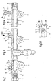
- Figure 1 shows a known embodiment of a high-pressure plenum with voltage-increasing Material accumulation on the connection thread of a high-pressure fuel line.
- the high-pressure fuel reservoir of a fuel injection system comprises a tubular one trained base body, which extends substantially in the longitudinal direction Cavity 2 limited in the form of a blind hole.
- the one that forms the cavity The blind hole within the tubular base body 1 is in a section 3 formed with a larger diameter and in a section 4 with a smaller diameter.
- the section of the tubular base body 1, formed to a lesser extent Diameter, is provided with a closure 5, which according to the embodiment variant Figure 1 is designed as a plug with a threaded portion.
- an open end 6 is formed on the tubular base body 1, which in turn comprises an internal thread on which the connecting line for a high pressure source, not shown here, for example a high pressure pump, possibly can be connected upstream of a pre-feed pump.
- a high pressure source not shown here, for example a high pressure pump
- the section 3 with a larger diameter of the tubular base body 1 forms a the cavity 2 facing inner wall 7, which on one side of the tubular Basic body 1 of transverse bores 12 of a plurality of connections 8, 9 and 10 for high-pressure fuel lines is enforced.
- the internal combustion engine with fuel-supplying fuel injectors has a risk of breakage due to a high level of tension as internal pressure limiting proven by the material accumulation below the thread sections not shown here of the connections 8, 9 and 10 and the boundary wall of the tubular Base body 1 is caused.
- the tubular base body 1 On the connections for the high pressure fuel lines 8, 9 and 10 opposite side is the tubular base body 1 provided with fastening elements 11 for fastening to the internal combustion engine.
- Figure 2 shows a circumferential undercut between the connection thread and the outside of a high pressure collecting room.
- the tubular base body 1 shown in FIG. 2 only with its end section is provided with a connection for a high-pressure fuel line 8, which is from a Bore 12 is penetrated.
- the bore 12 opens into the section 3 of the tubular Base body 1, which is formed with a larger diameter.
- Port 8 for the High-pressure fuel line is provided with an external thread 13, to which Example in the form of a union nut to the high pressure line, not shown here Fuel injector can be connected.
- this measure ensures that the through a Blind hole 2 formed cavity of the tubular base body 1 over a longer Service life can be subjected to a higher internal pressure.
- the one at the Section 3 of larger diameter adjoining section 4 of the tubular Base body 1 is configured, for example, by a screw plug Closure 5 sealed to the outside.
- Figure 3 shows a further embodiment of a decoupling between connection and High-pressure plenum wall formed by two mutually opposite cutouts Undercut.
- FIG. 3 shows the middle section of a tubular base body 1 more clearly.
- the hollow of the tubular formed by a blind hole 2 Base body 1 is in the region of the mouth of the transverse bore 12 of the connection 9 formed in an enlarged diameter.
- On the inner wall 7 of the boundary wall 19 of the tubular base body 1 opens the bore 12.
- the connection 9 which also has an external thread 13 for connecting a high-pressure fuel line is provided, and the outside of the boundary wall 19 a local Undercut 15 is formed.
- the tubular Base body 1 is provided with several fastening elements 11 over its length with which the tubular base body serving as a high-pressure collecting space can be 1 is fastened in the cylinder head area of an internal combustion engine.
- a top view of the one shown in FIG. 3 goes from the illustration according to FIG Connection for a high-pressure fuel line.
- Figure 3.1 is the material removal designated by reference numerals 16 and 17, respectively around millings; instead of milling, the creation of recesses in the form of material removal below the external thread 13 at the connection 9 for the High pressure line can also be generated by other machining manufacturing processes. It is also conceivable for the undercuts to be produced directly as a forged part to produce the tubular base body 1.
- the material removal 16 and the further material removal 17 by an offset of 180 ° to each other exactly perpendicular to the boundary walls 19 of the tubular base body 1.
- the wall thickness of the boundary wall 19 of the serving as a high-pressure plenum tubular base body 1 is identified by reference numeral 20.
- FIG. 4 shows a further embodiment variant of the decoupling of a connection of the High-pressure plenum from the external thread by interposing a pipe section.
- a connection 10 is located in one by its length 23 of a pipe section 22 formed distance from the outside of the tubular Basic body 1.
- the connection 10 on the external thread 13 for connecting a High-pressure fuel line and the pipe section 22 and the boundary wall 19 of the tubular base body 1 is traversed by a bore 21 of increased length.
- This embodiment variant is compared to that in FIG. 2 as a circumferential undercut 14 or in FIG. 3 undercuts designed as local undercut 15 a pipe section 22 extended.
- the diameter of the undercut, i.e. the outside diameter the pipe section 22 is only from the internal pressure in the cavity 2 of the tubular base body 1 defined and can be selected so that the component to can be stressed to the limit of elastic deformation, since no stress increases can occur due to discontinuous geometries.
- the decoupling of the connections 8, 9 or 10 proposed by the invention from the Wall 19 of the tubular base body 1 serving as a high-pressure collecting space avoids material accumulation in the transition area from the external thread 13 of the connections 8, 9 and 10 to the outside of the boundary wall 19 of the tubular Base body 1. This results in the transition area between the connections 8, 9 and 10 to the boundary wall 19 of the tubular base body 1 is a cheaper one Stress level, as a deformation hindrance due to material accumulation in this Area is now excluded.
Landscapes
- Engineering & Computer Science (AREA)
- Chemical & Material Sciences (AREA)
- Combustion & Propulsion (AREA)
- Mechanical Engineering (AREA)
- General Engineering & Computer Science (AREA)
- Fuel-Injection Apparatus (AREA)
Applications Claiming Priority (2)
| Application Number | Priority Date | Filing Date | Title |
|---|---|---|---|
| DE10132245 | 2001-07-04 | ||
| DE10132245A DE10132245A1 (de) | 2001-07-04 | 2001-07-04 | Druckfester Hochdrucksammelraum |
Publications (2)
| Publication Number | Publication Date |
|---|---|
| EP1273794A2 true EP1273794A2 (fr) | 2003-01-08 |
| EP1273794A3 EP1273794A3 (fr) | 2003-03-26 |
Family
ID=7690470
Family Applications (1)
| Application Number | Title | Priority Date | Filing Date |
|---|---|---|---|
| EP02014391A Withdrawn EP1273794A3 (fr) | 2001-07-04 | 2002-06-28 | Accumulateur à haute pression |
Country Status (4)
| Country | Link |
|---|---|
| US (1) | US20030084880A1 (fr) |
| EP (1) | EP1273794A3 (fr) |
| JP (1) | JP2003056427A (fr) |
| DE (1) | DE10132245A1 (fr) |
Cited By (3)
| Publication number | Priority date | Publication date | Assignee | Title |
|---|---|---|---|---|
| EP2667011A3 (fr) * | 2012-05-23 | 2014-05-07 | Otics Corporation | Procédé de production d'un tuyau de distribution de carburant |
| EP3315762A1 (fr) * | 2016-10-28 | 2018-05-02 | Delphi International Operations Luxembourg S.à r.l. | Agencement intégré d'une rampe commune et d'un capteur de pression |
| WO2018184799A1 (fr) * | 2017-04-04 | 2018-10-11 | Robert Bosch Gmbh | Accumulateur à haute pression pour carburant |
Families Citing this family (3)
| Publication number | Priority date | Publication date | Assignee | Title |
|---|---|---|---|---|
| DE602005016390D1 (de) * | 2005-07-08 | 2009-10-15 | Fiat Ricerche | Verbindungssystem von einem rohrförmigen Speicher für Hochdruckkraftstoff |
| DE102008035462B4 (de) | 2008-07-30 | 2022-10-27 | Mercedes-Benz Group AG | Railbaugruppe einer Kraftstoffeinspritzanlage |
| US10801457B1 (en) * | 2019-07-03 | 2020-10-13 | Delphi Technologies Ip Limited | Fuel rail assembly providing connection to a fuel injector |
Citations (1)
| Publication number | Priority date | Publication date | Assignee | Title |
|---|---|---|---|---|
| DE19936533A1 (de) | 1999-08-03 | 2001-02-15 | Bosch Gmbh Robert | Kraftstoffhochdruckspeicher |
Family Cites Families (7)
| Publication number | Priority date | Publication date | Assignee | Title |
|---|---|---|---|---|
| JP3292017B2 (ja) * | 1996-01-16 | 2002-06-17 | トヨタ自動車株式会社 | V型エンジンの燃料供給装置 |
| DE19607521C1 (de) * | 1996-02-28 | 1997-04-10 | Juergen Dipl Ing Guido | Kraftstoff-Verteilerrohr |
| CA2230742A1 (fr) * | 1997-03-03 | 1998-09-03 | Usui Kokusai Sangyo Kaisha Limited | Rampe commune et methode de fabrication |
| JP2000234688A (ja) * | 1999-02-17 | 2000-08-29 | Usui Internatl Ind Co Ltd | コモンレールの製造方法 |
| DE19948338A1 (de) * | 1999-10-07 | 2001-04-12 | Bosch Gmbh Robert | Verfahren zur Bearbeitung eines Kraftstoffhochdruckspeichers, Kraftstoffhochdruckspeicher und Anschlussstutzen zur Anwendung des Verfahrens |
| DE10019133A1 (de) * | 2000-04-18 | 2001-10-25 | Porsche Ag | Einspritzvorrichtung für eine Brennkraftmaschine |
| US6269804B1 (en) * | 2000-04-26 | 2001-08-07 | Delphi Technologies, Inc. | Coaxial liquid cooled fuel rail assembly |
-
2001
- 2001-07-04 DE DE10132245A patent/DE10132245A1/de not_active Ceased
-
2002
- 2002-06-28 EP EP02014391A patent/EP1273794A3/fr not_active Withdrawn
- 2002-07-02 US US10/188,240 patent/US20030084880A1/en not_active Abandoned
- 2002-07-03 JP JP2002194220A patent/JP2003056427A/ja not_active Abandoned
Patent Citations (1)
| Publication number | Priority date | Publication date | Assignee | Title |
|---|---|---|---|---|
| DE19936533A1 (de) | 1999-08-03 | 2001-02-15 | Bosch Gmbh Robert | Kraftstoffhochdruckspeicher |
Cited By (4)
| Publication number | Priority date | Publication date | Assignee | Title |
|---|---|---|---|---|
| EP2667011A3 (fr) * | 2012-05-23 | 2014-05-07 | Otics Corporation | Procédé de production d'un tuyau de distribution de carburant |
| US9303609B2 (en) | 2012-05-23 | 2016-04-05 | Otics Corporation | Method of producing fuel distribution pipe |
| EP3315762A1 (fr) * | 2016-10-28 | 2018-05-02 | Delphi International Operations Luxembourg S.à r.l. | Agencement intégré d'une rampe commune et d'un capteur de pression |
| WO2018184799A1 (fr) * | 2017-04-04 | 2018-10-11 | Robert Bosch Gmbh | Accumulateur à haute pression pour carburant |
Also Published As
| Publication number | Publication date |
|---|---|
| EP1273794A3 (fr) | 2003-03-26 |
| JP2003056427A (ja) | 2003-02-26 |
| US20030084880A1 (en) | 2003-05-08 |
| DE10132245A1 (de) | 2003-01-23 |
Similar Documents
| Publication | Publication Date | Title |
|---|---|---|
| EP1982070B1 (fr) | Corps d'accumulation a haute pression a bloc de repartition integre | |
| EP0864043B1 (fr) | Accumulateur de carburant haute pression | |
| EP1904741B1 (fr) | Systeme d'injection d'accumulateur pour moteur a combustion interne | |
| EP3165760B1 (fr) | Distributeur de carburant | |
| EP1137879B1 (fr) | Procede d'usinage d'un accumulateur de combustible haute pression, accumulateur de combustible haute pression et raccord pour l'application du procede | |
| DE102008000144B4 (de) | Common Rail | |
| DE102004001103A1 (de) | Hochdruckkraftstoffsammelvorrichtung | |
| EP1049868B1 (fr) | Systeme de pompes pour alimentation en carburant sous haute pression | |
| EP1137878B1 (fr) | Accumulateur de carburant haute pression | |
| EP1117924B1 (fr) | Accumulateur de carburant haute pression | |
| EP3759337A1 (fr) | Dispositif de distribution d'un système d'injection directe à rampe commune | |
| DE19945316A1 (de) | Kraftstoffhochdruckspeicher | |
| DE102016201082B4 (de) | Kraftstoffhochdruckpumpe | |
| EP1273794A2 (fr) | Accumulateur à haute pression | |
| EP1188926B1 (fr) | Pompe d'alimentation pour rampe d'alimentation en essence | |
| EP1144854B1 (fr) | Reservoir de carburant haute pression | |
| DE19937946C1 (de) | Kraftstoffhochdruckspeicher für ein Kraftstoffeinspritzsystem für Brennkraftmaschinen | |
| DE10242894A1 (de) | Kraftstoff-Einspritzsystem und Zylinderkopf mit einem zentralen Kraftstoffspeicher | |
| DE102006049224B4 (de) | Kraftstoffversorgungsanlage einer Brennkraftmaschine | |
| DE102006014767A1 (de) | Kraftstoffeinspritzeinrichtung für eine mehrzylindrige Brennkraftmaschine | |
| CH712276A1 (de) | Speichereinspritzsystem für Verbrennungskraftmaschinen. | |
| DE19936685A1 (de) | Kraftstoffhochdruckspeicher | |
| EP1133634B1 (fr) | Accumulateur de carburant haute pression | |
| EP1527272B1 (fr) | Injecteur de carburant comprenant une zone de raccordement resistant a haute pression | |
| DE102007000419A1 (de) | Kraftstoffsammelvorrichtung mit einer Buchse, in der eine Öffnung ausgebildet ist |
Legal Events
| Date | Code | Title | Description |
|---|---|---|---|
| PUAI | Public reference made under article 153(3) epc to a published international application that has entered the european phase |
Free format text: ORIGINAL CODE: 0009012 |
|
| AK | Designated contracting states |
Kind code of ref document: A2 Designated state(s): AT BE CH CY DE DK ES FI FR GB GR IE IT LI LU MC NL PT SE TR |
|
| AX | Request for extension of the european patent |
Free format text: AL;LT;LV;MK;RO;SI |
|
| PUAL | Search report despatched |
Free format text: ORIGINAL CODE: 0009013 |
|
| AK | Designated contracting states |
Kind code of ref document: A3 Designated state(s): AT BE CH CY DE DK ES FI FR GB GR IE IT LI LU MC NL PT SE TR Designated state(s): AT BE CH CY DE DK ES FI FR GB GR IE IT LI LU MC NL PT SE TR |
|
| AX | Request for extension of the european patent |
Extension state: AL LT LV MK RO SI |
|
| 17P | Request for examination filed |
Effective date: 20030926 |
|
| AKX | Designation fees paid |
Designated state(s): DE FR IT |
|
| 17Q | First examination report despatched |
Effective date: 20031202 |
|
| STAA | Information on the status of an ep patent application or granted ep patent |
Free format text: STATUS: THE APPLICATION IS DEEMED TO BE WITHDRAWN |
|
| 18D | Application deemed to be withdrawn |
Effective date: 20040414 |