EP1273484A2 - Überrollschutzsystem für Kraftfahrzeuge - Google Patents
Überrollschutzsystem für Kraftfahrzeuge Download PDFInfo
- Publication number
- EP1273484A2 EP1273484A2 EP02011127A EP02011127A EP1273484A2 EP 1273484 A2 EP1273484 A2 EP 1273484A2 EP 02011127 A EP02011127 A EP 02011127A EP 02011127 A EP02011127 A EP 02011127A EP 1273484 A2 EP1273484 A2 EP 1273484A2
- Authority
- EP
- European Patent Office
- Prior art keywords
- rollover
- designed
- protection system
- locking
- rack
- Prior art date
- Legal status (The legal status is an assumption and is not a legal conclusion. Google has not performed a legal analysis and makes no representation as to the accuracy of the status listed.)
- Granted
Links
Images


Classifications
-
- B—PERFORMING OPERATIONS; TRANSPORTING
- B60—VEHICLES IN GENERAL
- B60R—VEHICLES, VEHICLE FITTINGS, OR VEHICLE PARTS, NOT OTHERWISE PROVIDED FOR
- B60R21/00—Arrangements or fittings on vehicles for protecting or preventing injuries to occupants or pedestrians in case of accidents or other traffic risks
- B60R21/02—Occupant safety arrangements or fittings, e.g. crash pads
- B60R21/13—Roll-over protection
-
- B—PERFORMING OPERATIONS; TRANSPORTING
- B60—VEHICLES IN GENERAL
- B60R—VEHICLES, VEHICLE FITTINGS, OR VEHICLE PARTS, NOT OTHERWISE PROVIDED FOR
- B60R21/00—Arrangements or fittings on vehicles for protecting or preventing injuries to occupants or pedestrians in case of accidents or other traffic risks
- B60R21/02—Occupant safety arrangements or fittings, e.g. crash pads
- B60R21/13—Roll-over protection
- B60R2021/132—Roll bars for convertible vehicles
- B60R2021/134—Roll bars for convertible vehicles movable from a retracted to a protection position
- B60R2021/135—Roll bars for convertible vehicles movable from a retracted to a protection position automatically during an accident
Definitions
- Rollover protection systems of this type serve to protect the occupants in Motor vehicles without a protective roof, typically in convertibles or Sports cars.
- the holding device typically has a holding element fastened to the rollover body, which is in releasable mechanical operative connection with a triggering element on a sensor-controlled triggering system, which is typically formed by a triggering magnet, the so-called crash magnet, or by a pyrotechnic triggering element.
- the locking device typically consists of a pivotably articulated, spring-loaded latching pawl with toothed segments and a fixed toothed rack, a locking pin or the like, one locking element being connected to the roll bar and the other fixed to the vehicle.
- Such a cassette construction of a roll bar protection system with a U-shaped roll bar is shown for example in DE 43 42 400 A1; an alternative cassette construction with a rollover body in the form of a profile body is shown in particular in DE 195 23 790 C1 and DE 198 38 989 C1.
- the known rollover protection system according to DE 43 42 400 A1 has a housing in the form of a U-shaped cassette that is open on one side, with two side walls, each of which has an angled-out section on the open side of the cassette for fastening the cassette to the vehicle to which a floor panel is still attached, and which are finally connected to one another at the front via a cover wall.
- the rollover protection system also has a U-shaped roll bar consisting of a curved section and two parallel leg tubes, each of which has a closed outer surface, and the open ends of which are connected to one another via a crossbar-like, stiffening connecting element.
- the system also has two standpipes, which are attached to the bottom of the housing at one end and each contain a compression spring for the sole drive of the roll bar, each of which is coaxially encompassed by a leg tube and also have a closed jacket surface and a flat surface at the upper end of the housing attached to the side walls of the cassette, which has guide openings for additional external guidance of the leg tubes.
- the known alternative rollover protection system according to DE 198 38 989 C1 has a rollover body, designed as a stiffened box section bracket body, which extends over the entire width of the temple, and which in one vehicle-fixed, box-like basic profile, the profile guide body, is led.
- a rollover body designed as a stiffened box section bracket body, which extends over the entire width of the temple, and which in one vehicle-fixed, box-like basic profile, the profile guide body, is led.
- the roll bar consists of a spectacle-like profile bracket body; the in a vehicle-fixed profile guide body that only extends over a portion of the bracket profile body, is guided.
- each have a toothed rack attached to the profile bracket body is screwed, and rotatable on the profile guide body Articulated tooth pawl, provided as a locking device.
- the rollover body, the profile guide body and its attachment in the vehicle and the locking device and their attachment which is particularly abrupt in the stirrup travel direction absorb the occurring load.
- the forces occurring here can be in Dependence on speed and mass of the vehicle, as well The angle of impact and the nature of the impact area according to the latest Exceptionally, a load of at least 10 tons amount, the typically occurring base load to which the systems are typically designed to be 6 - 6.5 tons.
- Rollover protection system to be designed as a reinforced, rigid system.
- the rollover body, the guide body and its attachment to Vehicle designed so that it loads up to the highest possible form a non-deformable, rigid system.
- the locking components and their fastening means i.e. the Dimensioning of the racks and their fastening screws or Specifically, the positive reception in the rollover body and the pawl and the bolt with which it is articulated in the guide body, including the Bearing of the pin in the guide body, designed for the very high load.
- the invention is based on the object of the type mentioned Rollover protection system to be designed so that even in the event of a rollover the roll forces occurring peak forces with portable dimensions of the Load-bearing elements can be caught so that the rollover protection function preserved.
- the target deformation point can be realized in different ways, for example, by an appropriately designed crumple zone.
- a particularly simple constructive option for a defined one Deformation path is given if according to an embodiment of the invention the locking component and / or the fastening thereof are designed in such a way that when a given load occurs a cutting Material deformation takes place via a predetermined path.
- the Cutting process enables a targeted, length-limited deformation to Energy reduction.
- each of the locking components can act as a target deformation point be formed.
- a locking device in the form of a provided with tooth-shaped locking elements, in the direction of travel extending, elongated rack element as one of the Locking components according to an embodiment of the invention Toothed strip element and / or its attachment in the rollover system as a target deformation point are trained.
- Toothed strip element and / or its attachment in the rollover system as a target deformation point are trained.
- Such a construction enables on simple way the desired cutting process for energy reduction.
- Toothed element is designed as a separate rack, with at least two screw connections is attached to the roll bar and additionally with a peg-shaped extension in a corresponding opening is held on the roll bar.
- a rollover protection system in which the Rollover body consists of a profile body and has a wall, to which the rack is attached and which the opening for receiving the has a peg-shaped extension, the wall and the peg so are designed so that when a given load occurs under the effect of Self-closing torque of the other locking component of the pin as Cutting tool cuts the wall for a given path.
- This Design allows a defined in a particularly simple manner Cutting process and thus a corresponding energy reduction.
- Toothed rack is formed, which is integrally formed on the rollover body, the rack and the integral cut surface on the rollover body so are designed so that when a predetermined load occurs, the teeth and cut the interface through the second locking component become.
- This alternative also allows targeted energy reduction a targeted cutting process on the rollover body.
- Rollover protection system designed so that in the mounting area Rack or the rack a progressively increasing wall thickness on Rollover body is provided.
- FIGS. 1 and 2 show in a first embodiment sections of a rollover protection system analogous to that after the initially cited DE 198 38 989 C1, to which herewith regarding the Disclosure is expressly referred to with a cassette-shaped, vehicle-mounted profile guide body 1 for Guidance of a profile roll body 2 consisting of a box profile, with additional guide elements 3 in the profile guide body 1 are attached.
- the profile roll body 2 has a central opening 4 to accommodate a (not shown) compression spring for the quick drive of the Rollover body 1.
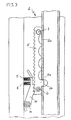
- a rack 5 as one of the two locking components attached. This attachment of the rack 5 is shown in more detail in FIG. 3.
- the rack has one Pin 5 a, the form-fitting in an opening 2 b of the wall 2 a is included.
- the second locking component is in a known manner by a by means of springs 8, 9 biased tooth pawl 10 formed on a bolt 11, which is mounted in the profile guide body 2, is pivotally supported.
- FIGS 1 and 3 show the locked state of the extended Rollover 2, in which the teeth of both locking components in interlocking active intervention.
- the rollover body 2, the associated guide body 1 and its Attachments to the vehicle are designed so that they, based on the maximum load occurring in the event of a rollover is designed as a rigid system are, i.e. not subject to deformation.
- the pin 5 a and its receiving area in the wall 2 a are now like this designed that when a certain force level is exceeded the Component Fz through the pin 5 a cutting the wall 2 a under A chip 2 c is peeled off, as shown in FIG. 4.
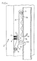
- Figures 5 and 6 show a second embodiment, in principle with the first embodiment according to FIGS. 1-4, like also shows the equality of the reference numerals, with the only difference, that instead of a separate rack 5 an integral in section 2 d of Rollover 2 molded rack 5 'is provided.
- the integral Forming a rack on one leg of a roll bar is in itself become known from DE 197 12 955 A1.
- the rack and the wall thickness of the toothing section 2 d are so stipulated that when the force peak of 10 or more tons by the force component Fz for cutting the teeth the rack 5 'and the tooth wall 2 d comes. Because of this Cutting cuts energy through deformation work. By a progressively increasing wall thickness can be achieved that the Cutting process automatically after a predetermined distance to a standstill comes.
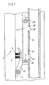
- FIG. 7 shows an embodiment of a rollover protection system with a target deformation point 1, the same parts with the same Reference numerals are provided, but in which the rack 5 a second Pin 5 b, which in a second opening 2 f in the wall 2 a Rollover body is added.
- area 2 c of the wall 2 a above the first pin 5 a, where the cutting process takes place is the wall thickness progressively increasing.
- the opening 2 f for the second pin 5 b is designed as an elongated hole with a stop edge 2 e.
- the wall area 2 c enables easy targeted cutting, and the stop edge 2 e, on which only has a reduced force, limits the incision.
- the Wall area 2 c can have different geometric configurations have to ensure a progressively increasing power loss. Also it is possible to use the wedge effect.
Landscapes
- Engineering & Computer Science (AREA)
- Mechanical Engineering (AREA)
- Slide Fasteners, Snap Fasteners, And Hook Fasteners (AREA)
- Lock And Its Accessories (AREA)
- Body Structure For Vehicles (AREA)
Abstract
Description
- einem Überrollkörper, der in einem fahrzeugfesten Führungskörper geführt aufgenommen ist, und der im Normalzustand gegen die Kraft von mindestens einer vorgespannten Antriebs-Druckfeder durch eine Haltevorrichtung in einer unteren, eingefahrenen Ruhelage haltbar ist, und unter Lösen der Haltevorrichtung durch die Federkraft der Antriebs-Druckfeder in eine obere, schützende Stellung bringbar ist, und mit
- einer Verriegelungseinrichtung für das Verriegeln des ausgefahrenen Überrollkörpers gegen ein ungewolltes Wiedereinfahren, bestehend aus zwei Verriegelungskomponenten, von denen eine fahrzeugfest angebracht und die andere mit dem Überrollkörper verbunden ist, und die Rastelemente besitzen, die in der ausgefahrenen Stellung des Überrollkörpers im verriegelnden Wirkeingriff stehen.
Dabei ist jedem Fahrzeugsitz eine Kassette zugeordnet.
Die Haltevorrichtung besitzt dabei typischerweise ein am Überrollkörper befestigtes Halteglied, das in lösbarer mechanischer Wirkverbindung mit einem Auslöseglied an einem sensorgesteuerten Auslösesystem steht, das typischerweise durch einen Auslösemagneten, den sogenannten Crashmagneten, oder durch ein pyrotechnisches Auslöseglied, gebildet ist.
Die Verriegelungseinrichtung besteht typischerweise aus einer schwenkbar angelenkten, federvorgespannten Rastklinke mit Zahnsegmenten und einer feststehenden Zahnleiste, einem Rastdorn oder dergleichen, wobei ein Verriegelungs-Element mit dem Überrollbügel und das andere fahrzeugfest verbunden ist.
DE 198 38 989 C1.
Das System weist ferner zwei mit einem Ende am Gehäuseboden angebrachte, im Innern jeweils eine Druckfeder für den alleinigen Antrieb des Überrollbügels aufnehmende, Standrohre, die jeweils von einem Schenkelrohr koaxial umgriffen sind und ebenfalls eine geschlossene Mantelfläche aufweisen sowie einen am oberen Ende des Gehäuses flächig an den Seitenwänden der Kassette angebrachten Führungsblock auf, der Führungsöffnungen zur zusätzlichen äußeren Führung der Schenkelrohre besitzt.
- erwies sich jedoch wirtschaftlich als nicht sinnvoll, weil insbesondere ein hoher Material-Aufwand betrieben werden müßte,
- benötigt einen entsprechend größeren Bauraum für die verstärkten Elemente, der in der Regel nicht zur Verfügung steht, so daß der Lastaufnahme Grenzen gesetzt waren, und
- birgt die Gefahr in sich, daß die Elemente der Wiedereinfahrsperre schlagartig zerstört werden und dadurch die Wiedereinfahrsperre ihre Schutzfunktion total verliert.
- einem Überrollkörper, der in einer fahrzeugfesten Führungseinheit geführt aufgenommen ist, und der im Normalzustand gegen die Kraft von mindestens einer vorgespannten Antriebs-Druckfeder durch eine Haltevorrichtung in einer unteren, eingefahrenen Ruhelage haltbar ist, und unter Lösen der Haltevorrichtung durch die Federkraft der Antriebs-Druckfeder in eine obere, schützende Stellung bringbar ist, und mit
- einer Verriegelungseinrichtung für das Verriegeln des ausgefahrenen Überrollkörpers gegen ein ungewolltes Wiedereinfahren, bestehend aus zwei Verriegelungskomponenten, von denen eine fahrzeugfest angebracht und die andere mit dem Überrollkörper verbunden ist, und die Rastelemente besitzen, die in der ausgefahrenen Stellung des Überrollkörpers im verriegelnden Wirkeingriff stehen,
- Fig. 1
- in einer schematischen Längsschnitt-Darstellung ein Überrollschutzsystem mit einem Überrollkörper in Form eines kastenartigen Profilkörpers, der in einem fahrzeugfesten Profilkörper geführt ist mit einer Verriegelungseinrichtung in Form einer Zahnstange und einer Zahnklinke, wobei die Zahnstange und ihre Befestigung als Soll-Deformationsstelle ausgebildet ist,
- Fig. 2
- eine Querschnittsansicht des Überrollschutzsystems nach Fig. 1 entlang des Schnittes A-A,
- Fig. 3
- in einer vergrößerten Ausschnitt-Darstellung die Befestigung der Zahnstange an einer Wandung des den Überrollkörper bildenden Profilkörpers,
- Fig. 4
- den Zustand der Lage der Zahnstange nach Auftreten einer Spitzenlast unter Darstellung des Einschneidvorganges,
- Fig. 5
- eine alternative Ausführungsform zur Fig. 1 mit einer Zahnleiste, die integral mit dem Überrollkörper verbunden ist, anstelle einer separat angebrachten Zahnstange,
- Fig. 6
- in einer Querschnitts-Darstellung eine Schnittansicht entlang der Schnittlinie B-B in Fig. 5, und
- Fig. 7
- in einer Querschnitts-Darstellung auf der Basis der Ausführung nach Fig. 1 eine konstruktive Möglichkeit zur Begrenzung des Einschneidvorganges.
- die Breite des Zapfens 5 a und der Öffnung 2 b, und
- die Wandstärke der einzuschneidenden Wandung 2 a.
Claims (8)
- Überrollschutzsystem für Kraftfahrzeuge, mitdadurch gekennzeichnet, daß der Überrollkörper (2), der zugeordnete Führungskörper (1) und dessen Befestigung am Fahrzeug, bezogen auf die bei einem Überschlag auftretende Maximallast als starres System ausgebildet sind, und mindestens eine Verriegelungskomponente (5, 5') und/oder deren Befestigung am Überroll- bzw. Führungskörper als definierte Soll-Deformationsstelle für einen begrenzten definierten Deformationsweg in Verfahrrichtung des Überrollkörpers zum Energieabbau ausgebildet ist.einem Überrollkörper (2), der in einem fahrzeugfesten Führungskörper (1) geführt aufgenommen ist, und der im Normalzustand gegen die Kraft von mindestens einer vorgespannten Antriebs-Druckfeder durch eine Haltevorrichtung in einer unteren, eingefahrenen Ruhelage haltbar ist, und unter Lösen der Haltevorrichtung durch die Federkraft der Antriebs-Druckfeder in eine obere, schützende Stellung bringbar ist, und miteiner Verriegelungseinrichtung (5, 10; 5', 10) für das Verriegeln des ausgefahrenen Überrollkörpers (2) gegen ein ungewolltes Wiedereinfahren, bestehend aus zwei
Verriegelungskomponenten, von denen eine fahrzeugfest angebracht und die andere mit dem Überrollkörper verbunden ist, und die Rastelemente besitzen, die in der ausgefahrenen Stellung des Überrollkörpers im verriegelnden Wirkeingriff stehen, - Überrollschutzsystem nach Anspruch 1, dadurch gekennzeichnet, daß die Verriegelungskomponente (5, 5') und/oder deren Befestigung so ausgebildet sind, daß bei Auftreten einer vorgegebenen Last eine schneidende Materialverformung über einen vorgegebenen Weg erfolgt.
- Überrollschutzsystem nach Anspruch 1 oder 2, mit einer Verriegelungseinrichtung in Form eines mit zahnförmigen Rastelementen versehenen, sich in Verfahrrichtung erstreckenden, länglichen Zahnleistenelementes als eine der Verriegelungskomponenten, dadurch gekennzeichnet, daß das Zahnleistenelement (5, 5') und/oder seine Befestigung im Überrollsystem (2) als Soll-Deformationsstelle ausgebildet sind.
- Überrollschutzsystem nach Anspruch 3, dadurch gekennzeichnet, daß das Zahnleistenelement als separate Zahnstange ausgebildet ist, die mit mindestens zwei Schraubverbindungen am Überrollkörper (2) befestigt ist und zusätzlich mit einem zapfenförmigen Fortsatz (5 a) formschlüssig in einer entsprechenden Öffnung (2 b) am Überrollkörper (2) gehaltert ist.
- Überrollschutzsystem nach Anspruch 4, bei dem der Überrollkörper (2) aus einem Profil-Körper besteht und eine Wandung (2 a) aufweist, an der die Zahnstange (5) befestigt ist, und welche die Öffnung (2 b) zur Aufnahme des zapfenförmigen Fortsatzes (5 a) aufweist, wobei die Wandung (2 a) und der Zapfen (5 a) so ausgelegt sind, daß beim Auftreten einer vorgegebenen Last unter Wirkung des Selbstschließmomentes der anderen Verriegelungskomponente (10) der Zapfen (5 a) als Schneidwerkzeug die Wandung (2 a) für einen vorgegebenen Weg schneidet.
- Überrollschutzsystem nach Anspruch 3, dadurch gekennzeichnet, daß das Zahnleistenelement als Zahnleiste (5') ausgebildet ist, die einstückig am Überrollkörper (2) angeformt ist, wobei die Zahnleiste (5') und die integrale Schnittstelle (2 d) am Überrollkörper (2) so ausgebildet sind, daß beim Auftreten einer vorgegebenen Last die Zähne und die Schnittstelle durch die zweite Verriegelungskomponente 10 geschnitten werden.
- Überrollschutzsystem nach Anspruch 5 oder 6, dadurch gekennzeichnet, daß im Befestigungsbereich der Zahnstange (5) bzw. der Zahnleiste (5') eine progressiv ansteigende Wandstärke am Überrollkörper (2) vorgesehen ist.
- Überrollschutzsystem nach Anspruch 5 oder 7, dadurch gekennzeichnet, daß die Zahnstange (5) einen zweiten zapfenförmigen Fortsatz (5 b) aufweist, der in einer weiteren, langlochartigen Öffnung (2 f) der Wandung (2), die eine Anschlagkante (2 e) zur Begrenzung der Bewegung der Zahnstange (5) bei der vorgegebenen Last besitzt, aufgenommen ist.
Applications Claiming Priority (2)
| Application Number | Priority Date | Filing Date | Title |
|---|---|---|---|
| DE10132421 | 2001-07-04 | ||
| DE10132421A DE10132421C1 (de) | 2001-07-04 | 2001-07-04 | Überrollschutzsystem für Kraftfahrzeuge |
Publications (3)
| Publication Number | Publication Date |
|---|---|
| EP1273484A2 true EP1273484A2 (de) | 2003-01-08 |
| EP1273484A3 EP1273484A3 (de) | 2004-09-22 |
| EP1273484B1 EP1273484B1 (de) | 2005-12-14 |
Family
ID=7690587
Family Applications (1)
| Application Number | Title | Priority Date | Filing Date |
|---|---|---|---|
| EP20020011127 Expired - Lifetime EP1273484B1 (de) | 2001-07-04 | 2002-05-18 | Überrollschutzsystem für Kraftfahrzeuge |
Country Status (3)
| Country | Link |
|---|---|
| EP (1) | EP1273484B1 (de) |
| DE (2) | DE10132421C1 (de) |
| ES (1) | ES2252353T3 (de) |
Cited By (1)
| Publication number | Priority date | Publication date | Assignee | Title |
|---|---|---|---|---|
| EP2384939A1 (de) * | 2011-02-04 | 2011-11-09 | ISE Automotive GmbH | Überrollschutzsystem für Kraftfahrzeuge |
Families Citing this family (8)
| Publication number | Priority date | Publication date | Assignee | Title |
|---|---|---|---|---|
| DE102006041261A1 (de) * | 2006-09-02 | 2008-03-06 | Wilhelm Karmann Gmbh | Überrollschutzsystem für ein Cabriolet-Fahrzeug |
| DE102007005517B4 (de) | 2007-02-03 | 2010-09-30 | Ise Automotive Gmbh | Überrollschutzsystem für Kraftfahrzeuge mit einem aktiv aufstellbaren Überrollkörper mit integriertem Deformationselement |
| EP2147831B1 (de) * | 2008-07-22 | 2011-03-02 | ISE Automotive GmbH | Überrollschutzsystem für Kraftfahrzeuge |
| DE102009011066A1 (de) * | 2009-02-28 | 2010-09-02 | Wilhelm Karmann Gmbh | Überrollschutzsystem für ein Cabriolet-Fahrzeug mit einem separaten Zahnprofil |
| DE102009052169A1 (de) * | 2009-11-06 | 2011-05-12 | Wilhelm Karmann Gmbh | Überrollschutzvorrichtung |
| DE102010036783A1 (de) * | 2010-05-04 | 2011-11-10 | Alutech Gesellschaft M.B.H. | Deckelvorrichtung für Profilelemente eines Überrollschutzsystems, Überrollschutzsystem mit einer Deckelvorrichtung sowie Klapperschutzvorrichtung |
| DE102012109813A1 (de) | 2012-10-15 | 2014-04-17 | Benteler Automobiltechnik Gmbh | Überrollschutzsystem mit Deformationselement |
| DE102013103204B4 (de) * | 2013-03-28 | 2018-11-08 | Benteler Automobiltechnik Gmbh | Überrollschutzsystem für Kraftfahrzeuge |
Citations (5)
| Publication number | Priority date | Publication date | Assignee | Title |
|---|---|---|---|---|
| DE4342400A1 (de) | 1993-08-03 | 1995-02-09 | Teves Gmbh Alfred | Überrollbügeleinrichtung mit Innenführung und Außenführung |
| DE4314538C2 (de) | 1993-05-03 | 1995-11-16 | Bayerische Motoren Werke Ag | Überrollschutz-Vorrichtung für ein Kraftfahrzeug |
| DE19523790A1 (de) | 1995-07-04 | 1997-01-09 | Teves Gmbh Alfred | Ausfahrbarer Überrollbügel |
| DE19712955A1 (de) | 1997-03-27 | 1998-10-01 | Bayerische Motoren Werke Ag | Überrollschutzsystem für ein Fahrzeug, insbesondere für ein Cabriolet |
| DE19838989C1 (de) | 1998-08-27 | 1999-11-11 | Ise Gmbh | Überroll-Schutzvorrichtung |
Family Cites Families (2)
| Publication number | Priority date | Publication date | Assignee | Title |
|---|---|---|---|---|
| DE19604423A1 (de) * | 1996-02-07 | 1997-08-14 | Bayerische Motoren Werke Ag | Überrollschutz für ein Kraftfahrzeug |
| DE19931224A1 (de) * | 1999-07-06 | 2001-01-11 | Bayerische Motoren Werke Ag | Überrollschutzsystem für ein Fahrzeug |
-
2001
- 2001-07-04 DE DE10132421A patent/DE10132421C1/de not_active Expired - Fee Related
-
2002
- 2002-05-18 EP EP20020011127 patent/EP1273484B1/de not_active Expired - Lifetime
- 2002-05-18 ES ES02011127T patent/ES2252353T3/es not_active Expired - Lifetime
- 2002-05-18 DE DE50205250T patent/DE50205250D1/de not_active Expired - Lifetime
Patent Citations (5)
| Publication number | Priority date | Publication date | Assignee | Title |
|---|---|---|---|---|
| DE4314538C2 (de) | 1993-05-03 | 1995-11-16 | Bayerische Motoren Werke Ag | Überrollschutz-Vorrichtung für ein Kraftfahrzeug |
| DE4342400A1 (de) | 1993-08-03 | 1995-02-09 | Teves Gmbh Alfred | Überrollbügeleinrichtung mit Innenführung und Außenführung |
| DE19523790A1 (de) | 1995-07-04 | 1997-01-09 | Teves Gmbh Alfred | Ausfahrbarer Überrollbügel |
| DE19712955A1 (de) | 1997-03-27 | 1998-10-01 | Bayerische Motoren Werke Ag | Überrollschutzsystem für ein Fahrzeug, insbesondere für ein Cabriolet |
| DE19838989C1 (de) | 1998-08-27 | 1999-11-11 | Ise Gmbh | Überroll-Schutzvorrichtung |
Cited By (1)
| Publication number | Priority date | Publication date | Assignee | Title |
|---|---|---|---|---|
| EP2384939A1 (de) * | 2011-02-04 | 2011-11-09 | ISE Automotive GmbH | Überrollschutzsystem für Kraftfahrzeuge |
Also Published As
| Publication number | Publication date |
|---|---|
| EP1273484B1 (de) | 2005-12-14 |
| ES2252353T3 (es) | 2006-05-16 |
| DE50205250D1 (de) | 2006-01-19 |
| EP1273484A3 (de) | 2004-09-22 |
| DE10132421C1 (de) | 2002-07-25 |
Similar Documents
| Publication | Publication Date | Title |
|---|---|---|
| EP3268260B1 (de) | Lenksäule für ein kraftfahrzeug | |
| DE4345523C2 (de) | Überrollschutzsystem | |
| EP1153805B1 (de) | Sicherheitseinrichtung für die Lagerung von Pedalen | |
| DE60317089T2 (de) | Zusammensackbares pedalgehäuse | |
| EP1288079A1 (de) | Überrollschutzsystem für Kraftfahrzeuge mit Soll-Deformationsstelle | |
| EP0537454B1 (de) | Sicherheitsvorrichtung | |
| DE102012016211A1 (de) | Gurtschlossbringer | |
| EP1072485A2 (de) | Sicherheitsgurtsystem | |
| DE69701012T2 (de) | Bei einem Stoss aktive Rückzugeinrichtung einer Kraftfahrzeug-Lenksäule | |
| DE10132421C1 (de) | Überrollschutzsystem für Kraftfahrzeuge | |
| DE10358774A1 (de) | Haltevorrichtung für eine Fahrzeugsicherheitseinrichtung | |
| DE19925520C1 (de) | Überroll-Schutzsystem für Kraftfahrzeuge | |
| DE10223420C2 (de) | Überrollschutzsystem für Kraftfahrzeuge mit Soll-Deformationsstelle | |
| DE2247921A1 (de) | Sitz mit verstellbarer rueckenlehne | |
| EP1227011B1 (de) | Überrollschutzsystem für Kraftfahrzeuge | |
| DE102011075267B4 (de) | Scharniereinrichtung für eine Frontklappe eines Kraftfahrzeugs, die in eine Fußgängerschutzlage hochstellbar ist | |
| DE10352275B4 (de) | Einrichtung zum Reversieren einer zum Unfallschutz sensorgesteuert aktiv aufgestellten Fronthaube eines Kraftfahrzeuges | |
| EP1344692B1 (de) | Überrollschutzsystem für Kraftfahrzeuge | |
| DE102016210875A1 (de) | Vorrichtung zur Freigabe einer Bewegung einer Komponente sowie Sitz mit einer solchen Vorrichtung | |
| EP1227012B1 (de) | Überrollschutzsystem für Kraftfahrzeuge | |
| EP2566726A1 (de) | Rahmenvorrichtung für ein überrollschutzsystem und überrollschutzsystem mit einer rahmenvorrichtung | |
| EP1955907B1 (de) | Überrollschutzsystem mit Überrollbügel für Kraftfahrzeuge | |
| EP1536976A1 (de) | Ablagetisch für ein kraftfahrzeug | |
| DE102011018388B4 (de) | Querträger für eine Karosserie eines Kraftwagens | |
| DE10103245C1 (de) | Überrollschutzsystem für Kraftfahrzeuge |
Legal Events
| Date | Code | Title | Description |
|---|---|---|---|
| PUAI | Public reference made under article 153(3) epc to a published international application that has entered the european phase |
Free format text: ORIGINAL CODE: 0009012 |
|
| 17P | Request for examination filed |
Effective date: 20020520 |
|
| AK | Designated contracting states |
Kind code of ref document: A2 Designated state(s): AT BE CH CY DE DK ES FI FR GB GR IE IT LI LU MC NL PT SE TR |
|
| AX | Request for extension of the european patent |
Free format text: AL;LT;LV;MK;RO;SI |
|
| PUAL | Search report despatched |
Free format text: ORIGINAL CODE: 0009013 |
|
| AK | Designated contracting states |
Kind code of ref document: A3 Designated state(s): AT BE CH CY DE DK ES FI FR GB GR IE IT LI LU MC NL PT SE TR |
|
| AX | Request for extension of the european patent |
Extension state: AL LT LV MK RO SI |
|
| AKX | Designation fees paid |
Designated state(s): DE ES FR GB IT |
|
| GRAP | Despatch of communication of intention to grant a patent |
Free format text: ORIGINAL CODE: EPIDOSNIGR1 |
|
| GRAS | Grant fee paid |
Free format text: ORIGINAL CODE: EPIDOSNIGR3 |
|
| GRAA | (expected) grant |
Free format text: ORIGINAL CODE: 0009210 |
|
| AK | Designated contracting states |
Kind code of ref document: B1 Designated state(s): DE ES FR GB IT |
|
| REG | Reference to a national code |
Ref country code: GB Ref legal event code: FG4D Free format text: NOT ENGLISH |
|
| REF | Corresponds to: |
Ref document number: 50205250 Country of ref document: DE Date of ref document: 20060119 Kind code of ref document: P |
|
| GBT | Gb: translation of ep patent filed (gb section 77(6)(a)/1977) |
Effective date: 20060316 |
|
| REG | Reference to a national code |
Ref country code: ES Ref legal event code: FG2A Ref document number: 2252353 Country of ref document: ES Kind code of ref document: T3 |
|
| ET | Fr: translation filed | ||
| PLBE | No opposition filed within time limit |
Free format text: ORIGINAL CODE: 0009261 |
|
| STAA | Information on the status of an ep patent application or granted ep patent |
Free format text: STATUS: NO OPPOSITION FILED WITHIN TIME LIMIT |
|
| 26N | No opposition filed |
Effective date: 20060915 |
|
| PGFP | Annual fee paid to national office [announced via postgrant information from national office to epo] |
Ref country code: ES Payment date: 20080523 Year of fee payment: 7 |
|
| PGFP | Annual fee paid to national office [announced via postgrant information from national office to epo] |
Ref country code: FR Payment date: 20090519 Year of fee payment: 8 Ref country code: IT Payment date: 20090526 Year of fee payment: 8 |
|
| PGFP | Annual fee paid to national office [announced via postgrant information from national office to epo] |
Ref country code: GB Payment date: 20090528 Year of fee payment: 8 |
|
| REG | Reference to a national code |
Ref country code: ES Ref legal event code: FD2A Effective date: 20090519 |
|
| PG25 | Lapsed in a contracting state [announced via postgrant information from national office to epo] |
Ref country code: ES Free format text: LAPSE BECAUSE OF NON-PAYMENT OF DUE FEES Effective date: 20090519 |
|
| GBPC | Gb: european patent ceased through non-payment of renewal fee |
Effective date: 20100518 |
|
| REG | Reference to a national code |
Ref country code: FR Ref legal event code: ST Effective date: 20110131 |
|
| PG25 | Lapsed in a contracting state [announced via postgrant information from national office to epo] |
Ref country code: IT Free format text: LAPSE BECAUSE OF NON-PAYMENT OF DUE FEES Effective date: 20100518 |
|
| PG25 | Lapsed in a contracting state [announced via postgrant information from national office to epo] |
Ref country code: FR Free format text: LAPSE BECAUSE OF NON-PAYMENT OF DUE FEES Effective date: 20100531 |
|
| PG25 | Lapsed in a contracting state [announced via postgrant information from national office to epo] |
Ref country code: GB Free format text: LAPSE BECAUSE OF NON-PAYMENT OF DUE FEES Effective date: 20100518 |
|
| REG | Reference to a national code |
Ref country code: DE Ref legal event code: R082 Ref document number: 50205250 Country of ref document: DE Representative=s name: KALKOFF & PARTNER PATENTANWAELTE, DE |
|
| REG | Reference to a national code |
Ref country code: DE Ref legal event code: R081 Ref document number: 50205250 Country of ref document: DE Owner name: METALSA AUTOMOTIVE GMBH, DE Free format text: FORMER OWNER: AUDI AG, ISE AUTOMOTIVE GMBH, , DE Effective date: 20130812 Ref country code: DE Ref legal event code: R081 Ref document number: 50205250 Country of ref document: DE Owner name: AUDI AG, DE Free format text: FORMER OWNER: AUDI AG, ISE AUTOMOTIVE GMBH, , DE Effective date: 20130812 Ref country code: DE Ref legal event code: R082 Ref document number: 50205250 Country of ref document: DE Representative=s name: KALKOFF & PARTNER PATENTANWAELTE, DE Effective date: 20130812 Ref country code: DE Ref legal event code: R082 Ref document number: 50205250 Country of ref document: DE Representative=s name: REBBEREH, CORNELIA, DIPL.-ING., DE Effective date: 20130812 Ref country code: DE Ref legal event code: R081 Ref document number: 50205250 Country of ref document: DE Owner name: AUDI AG, DE Free format text: FORMER OWNERS: AUDI AG, 85057 INGOLSTADT, DE; ISE AUTOMOTIVE GMBH, 51702 BERGNEUSTADT, DE Effective date: 20130812 Ref country code: DE Ref legal event code: R081 Ref document number: 50205250 Country of ref document: DE Owner name: METALSA AUTOMOTIVE GMBH, DE Free format text: FORMER OWNERS: AUDI AG, 85057 INGOLSTADT, DE; ISE AUTOMOTIVE GMBH, 51702 BERGNEUSTADT, DE Effective date: 20130812 |
|
| REG | Reference to a national code |
Ref country code: DE Ref legal event code: R082 Ref document number: 50205250 Country of ref document: DE Representative=s name: REBBEREH, CORNELIA, DIPL.-ING., DE |
|
| PGFP | Annual fee paid to national office [announced via postgrant information from national office to epo] |
Ref country code: DE Payment date: 20210504 Year of fee payment: 20 |
|
| REG | Reference to a national code |
Ref country code: DE Ref legal event code: R071 Ref document number: 50205250 Country of ref document: DE |