EP1273443B1 - Unité de support, système de support et procédé de support pour un dispositif d'impresssion - Google Patents
Unité de support, système de support et procédé de support pour un dispositif d'impresssion Download PDFInfo
- Publication number
- EP1273443B1 EP1273443B1 EP02014091A EP02014091A EP1273443B1 EP 1273443 B1 EP1273443 B1 EP 1273443B1 EP 02014091 A EP02014091 A EP 02014091A EP 02014091 A EP02014091 A EP 02014091A EP 1273443 B1 EP1273443 B1 EP 1273443B1
- Authority
- EP
- European Patent Office
- Prior art keywords
- control
- printing
- printer
- operation support
- information
- Prior art date
- Legal status (The legal status is an assumption and is not a legal conclusion. Google has not performed a legal analysis and makes no representation as to the accuracy of the status listed.)
- Expired - Lifetime
Links
- 238000000034 method Methods 0.000 title claims description 29
- 230000001629 suppression Effects 0.000 claims description 47
- 238000011156 evaluation Methods 0.000 claims description 22
- 230000000875 corresponding effect Effects 0.000 claims description 16
- 238000001514 detection method Methods 0.000 claims description 12
- 238000003860 storage Methods 0.000 claims description 9
- 230000002596 correlated effect Effects 0.000 claims description 8
- 230000000694 effects Effects 0.000 claims description 7
- 230000001276 controlling effect Effects 0.000 claims description 5
- 238000009826 distribution Methods 0.000 claims description 4
- 239000000470 constituent Substances 0.000 claims description 3
- XLYOFNOQVPJJNP-UHFFFAOYSA-N water Substances O XLYOFNOQVPJJNP-UHFFFAOYSA-N 0.000 description 45
- 238000007726 management method Methods 0.000 description 16
- 239000013598 vector Substances 0.000 description 12
- 230000008901 benefit Effects 0.000 description 10
- 238000004519 manufacturing process Methods 0.000 description 10
- 230000008569 process Effects 0.000 description 9
- 238000010276 construction Methods 0.000 description 8
- 230000008859 change Effects 0.000 description 6
- 238000010586 diagram Methods 0.000 description 6
- 239000011159 matrix material Substances 0.000 description 5
- 230000006641 stabilisation Effects 0.000 description 5
- 238000011105 stabilization Methods 0.000 description 5
- 238000004458 analytical method Methods 0.000 description 4
- 239000006185 dispersion Substances 0.000 description 4
- 230000006870 function Effects 0.000 description 4
- 238000007599 discharging Methods 0.000 description 3
- 230000000087 stabilizing effect Effects 0.000 description 3
- 238000002474 experimental method Methods 0.000 description 2
- 230000003993 interaction Effects 0.000 description 2
- 239000000463 material Substances 0.000 description 2
- 238000005259 measurement Methods 0.000 description 2
- 230000004048 modification Effects 0.000 description 2
- 238000012986 modification Methods 0.000 description 2
- 230000001052 transient effect Effects 0.000 description 2
- 238000004040 coloring Methods 0.000 description 1
- 230000008878 coupling Effects 0.000 description 1
- 238000010168 coupling process Methods 0.000 description 1
- 238000005859 coupling reaction Methods 0.000 description 1
- 238000005520 cutting process Methods 0.000 description 1
- 238000000354 decomposition reaction Methods 0.000 description 1
- 230000007812 deficiency Effects 0.000 description 1
- 238000011161 development Methods 0.000 description 1
- 230000004044 response Effects 0.000 description 1
- 239000008400 supply water Substances 0.000 description 1
Images


Classifications
-
- B—PERFORMING OPERATIONS; TRANSPORTING
- B41—PRINTING; LINING MACHINES; TYPEWRITERS; STAMPS
- B41F—PRINTING MACHINES OR PRESSES
- B41F33/00—Indicating, counting, warning, control or safety devices
- B41F33/0009—Central control units
-
- B—PERFORMING OPERATIONS; TRANSPORTING
- B41—PRINTING; LINING MACHINES; TYPEWRITERS; STAMPS
- B41P—INDEXING SCHEME RELATING TO PRINTING, LINING MACHINES, TYPEWRITERS, AND TO STAMPS
- B41P2233/00—Arrangements for the operation of printing presses
- B41P2233/10—Starting-up the machine
- B41P2233/11—Pre-inking
Definitions
- the present invention relates to an operation support unit, an operation support system, and an operation support method that automatically optimize a control quantity for each control object of a printer.
- the degree of ink key opening, the quantity of dampening water, and the adjustment quantities to paper supplying and discharging sections are important control quantities that have an influence upon the quality of a print. It is necessary that these control quantities be suitably adjusted for each job according to printing conditions (e.g., ink kind, paper kind, an image area rate, etc.). Adjustments to the control quantities depend on the skill of a person who operates a printer.
- an operation support system is disclosed, for example, in Japanese Laid-Open Patent Publication No. HEI 11-342597 .
- various kinds of control quantities for a printer are automatically controlled based on information about the interaction between control media, stored in an expert system.
- control quantities influence each other and therefore it is important to set optimal control quantities as a whole.
- the aforementioned operation information has errors in measurement, and errors due to the influence of various conditions that cannot be realistically taken into consideration. It is extremely important in executing the operation support of a printer with stability to estimate control characteristics with high reliability, based on a great number of data groups having such errors. In the above-mentioned publication there is no information on these points.
- the present invention has been made in view of the problems described above. Accordingly, it is the primary objective of the present invention to provide an operation support unit, an operation support system, and an operation support method for a printer which are capable of supporting operation of the printer with reliability and stability.
- an operation support unit for automatically setting control quantities of control objects for a printer, based on printing conditions for the printer, printing-quality information on a print, and mechanical information on the printer, and then outputting the set control quantities to a printer control unit which controls operation of the control objects of the printer, the operation support unit comprising:
- the allocation means gives the orders of priority to the plurality of control objects of the control group in the order that the effect of suppressing the suppression factor is higher.
- the quantity set means sets within the standard operating range a control quantity for a control object whose priority order is higher, based on the characteristic line and, when the control quantity alone cannot suppress the suppression factor, sets a control quantity for the control object having the next highest priority order, based on the characteristic line.
- control quantities for the plurality of control objects in the control group are simultaneously preset because the suppression factor cannot be suppressed by controlling the control quantity of a single control object of the control group within the standard operating range
- the control quantities are set so that the sum total of varied quantities of the control objects that are simultaneously preset becomes the minimum.
- the information collection means collects a set of data from among the plurality of data sets stored in the information storage means, when one condition is that an overall streak rate for an image is nearly the same as the present overall streak rate.
- control is performed according to the overall streak rate having a great influence on the control quantity of the control object, so that there is an advantage that operation support can be efficiently performed.
- an operation support system comprising:
- an operation support method of automatically optimizing control quantities of control objects for a printer comprising the steps of:
- a control group is allocated to each of the suppression factors, and a set of data that is under printing conditions nearly coinciding with the present predetermined printing conditions is collected from a great number of data sets in which printing conditions, printing-quality information, and mechanical information are correlated.
- a principal axis component which represents a distributed characteristic of the collected set of data is set as a characteristic line for the control objects selected as the control group. Therefore, a characteristic line with extremely high reliability is obtained based on a set of data, and a control quantity for a control object is set based on the characteristic line.
- the operation support system of the preferred embodiment is equipped with a production management server (printing condition output unit) 1, an editing station 2 where printed images are edited, a plurality of printing stations (e.g., two printing stations in the preferred embodiment) 3A, 3B, a shipping station 4 in which the final process (cutting, bookbinding, etc.) for prints is performed, and a fault analysis unit 5.
- Printing conditions including a target quality for a print, are stored in the production management server 1.
- the production management server 1 outputs the printing conditions to the printer control units 32 of the printing stations 3A, 3B.
- the printing stations 3A, 3B execute printing, based on the printing conditions.
- the printing conditions are information on production, material, etc., and is, for example, information on a number of prints, appointed data of delivery, ink kind, paper kind, blanket kind, dampening water kind, an image area rate, and ink quantity (target color for an image).
- the production management server 1 outputs page information (such as bookbinding, etc. ) , etc., to the shipping station 4.
- the print station 3A is equipped with a printer 31, a printer control unit 32, a printing operation support unit 33, and a printing quality management unit (printing quality detection unit) 34. Note that there are cases where the printing quality management unit 34 is shared with a plurality of printing stations.
- the printer 31 is connected with various constituent units such as a paper supplying unit, a plurality of printing units, a paper discharging unit, etc. Each unit is controlled by the printer control unit 32 provided within the same print station 3A. Each unit is also provided with one or more sensors (mechanical information detection means (not shown)) for detecting the conditions of the printer 31, that is, the mechanical conditions (mechanical information).
- the mechanical conditions that are detected are ambient temperature, ambient humidity, printing surface temperature, printing surface humidity, paper surface temperature, paper surface humidity, printing speed, rod pressure, printing pressure, etc.
- the information on the mechanical conditions detected by the sensors is output to the printer control unit 32.
- the information on the mechanical conditions is also output to the printing operation support unit 33 through the printer control unit 32.
- the printer control unit 32 also has the function of presetting the control quantities that the control objects of the printer 31 are controlled.
- the control objects that are controlled are a quantity of air handled, a quantity that a plate spring is pushed, a quantity of auxiliary air, etc.
- the control objects are a dampening water supply, a degree of an ink key opening, register, etc.
- they are a paper adjusting fan, a side jogger, a vacuum suction wheel, etc. If it receives the set value of each control quantity, which is to be described later, from the printing operation support unit 33, the printer control unit 32 presets each control quantity according to the set value.
- the printing quality management unit 34 is used to detect and manage the quality of a printing sheet (printed matter), and is constructed to output the detected printing-quality information to the printing operation support unit 33.
- the printing quality used herein means, for example, a color tone such as coloring, a color reproducing region, a color difference quantity, etc.
- the printing operation support unit 33 has a database (information storage means) 33a to which various kinds of printing information are input from the production management server 1 through the printer control unit 32.
- various kinds of mechanical information are input from the sensors of the printer 31 to the database 33a through the printer control unit 32.
- various kinds of printing-quality information are input from the printing quality management unit 34 to the database 33a.
- the printing information, the mechanical information, and the printing-quality information are correlated and stored in the database 33a as a set of data.
- the printing operation support unit 33 is also provided with all ocation means 33b.
- the allocation means 33b sets suppression factors which should be suppressed to achieve the object of supporting operation (control mode). For each suppression factor, the allocation means 33b further sets an evaluation parameter, and a control group for suppressing the suppression factor.
- Table 1 Objects Suppression factors Evaluation parameters Control groups a)Stabilization (steady state) 1) Ink film thickness fluctuation Color difference quantity A Ink supply Dampening water supply Ink temperature Oscillating amplitude 2)Color difference in a halftone region Color difference quantity B Ink supply Dampening water supply Ink temperature Printing pressure 3)Faults Stains, out-of-register Ink supply Dampening water supply Printing speed b) Early starting (transient state) 1) Paper supply stoppage Frequency of stoppages Printing speed Air pressure for feeding paper Paper feeding position Pawl height 2)Color mismatch Color difference quantity C Inter ink quantity Ink supply Water supplying method Ink temperature
- the evaluation parameter is printing quality that becomes a specific evaluation object for ascertaining the degree of a suppression factor.
- the control group is a group of control objects, selected to be effective in suppressing a suppression factor.
- the control objects within the control group are given the orders of priority in the order that the effect of suppressing a suppression object is higher. In Table 1, the control objects with a greater suppression effect are listed on the left side.
- the control-quantity set means 33d which is to be described later, sets the control quantities of the control objects in the order that the effect of suppressing a suppression factor is higher, and outputs them to the printer control unit 32.
- the printer control unit 32 presets the control quantity of each control object.
- the allocation means 33b As the object of supporting operation (i.e., as a control mode), a) the stabilization of quality under steady operation (stabilization of operation), and b) the early starting of a printer at the start of operation (in a transient state), are set. That is, the printing operation support unit 33 is provided with the function of stabilizing operation and the function of starting a printer early.
- the allocation means 33b sets 1) ink film thickness fluctuation, 2) a color difference in a halftone region, and 3) faults as the suppression factors.
- the allocation means 33b further sets a color difference quantity A, which is detected based on color coordinate values (L, a, b) by the printing quantity management unit 34, as the evaluation parameter, and sets an ink supply, a dampening water supply, ink temperature, and oscillating amplitude as the control group.
- the control-quantity set means 33d first presets, for example, an ink supply and a dampening water supply. If these presets cannot cause the color difference quantity A to be a predetermined value or less, then the control-quantity set means 33d presets ink temperature and oscillating amplitude.
- a color difference quantity B (the color coordinate values (L, a, b) and/or dot diameter ⁇ that is detected by the printing quality management unit 34) is set as the evaluation parameter, and an ink supply, a dampening water supply, ink temperature, and printing pressure are set as the control group.
- the faults, the stains and/or out-of-register that is detected by the printing quality management unit 34 is set as the evaluation parameter, and an ink supply, a dampening water supply, and printing speed are set as the control group.
- the allocation means 33b sets 1) a paper supply stoppage and 2) a color mismatch as the suppression factors.
- the allocation means 33b sets the frequency of stoppages that is recorded by the printer control unit 32, as the evaluation parameter, and sets printing speed, air pressure for feeding paper, paper feeding position, and pawl height as the control group.
- the color mismatch a color difference quantity C that is detected by the printing quality unit 34 is set as the evaluation parameter, and an inter-printing ink quantity, an ink supply, a water supplying method, and ink temperature are set as the control group.
- the printing operation support unit 33 is further provided with information collection means 33c and control-quantity set means 33d.
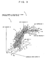
- information collection means 33c and control-quantity set means 33d A description will be given of how a color difference in a halftone region is suppressed by the information collection means 33c and the control-quantity set means 33d in order to stabilize operation, with reference to Fig. 3 .
- the information collection means 33c of the printing operation support unit 33 first collects the specific data sets d 1 , d 2 , d 3 , ⁇ from the database 33a in order to preset the ink supply I and dampening water supply W whose priority order is higher, among the control objects set by the allocation means 33b as the control group for suppressing a color difference in a halftone region which is an suppression factor.
- the specific data sets mean, the data set whose printing conditions are nearly the same as the present printing conditions, and furthermore, whose the ink temperature and printing pressure, set along with the ink supply I and the dampening water supply W as the control group for suppressing a color difference in a halftone region, are nearly equal to the presenting ink temperature and printing pressure, detected by the mechanical information detection means.
- control-quantity set means 33d conceptually marks the data sets d 1 , d 2 , d 3 , ⁇ on a first-order coordinate space S 1 having a corresponding evaluation parameter (e.g., a dot diameter ⁇ in this embodiment), an ink supply I, and a dampening water supply W as coordinate axes.
- a corresponding evaluation parameter e.g., a dot diameter ⁇ in this embodiment
- the data sets d 1 , d 2 , d 3 , ⁇ have errors in measurement and errors due to the influence of various conditions that cannot be realistically taken into consideration, respectively. Therefore, the characteristic population D of these data sets d 1 , d 2 , d 3 , ⁇ becomes a three-dimensional configuration having dispersion such as that shown in Fig. 3 . Because of this, the control-quantity set means 33d sets a principal axis, representing the distribution characteristic of the characteristic population D, as a characteristic line A. Based on the characteristic line A, the control quantities of the control objects (ink supply I and dampening water supply W) are set without influence of the error in the data sets d 1 , d 2 , d 3 , ⁇ . That is, when one condition is that a control point defined by the ink supply I and the dampening water supply W is on the characteristic line A, the control quantities of the ink supply I and the dampening water supply W can be set.
- the principal axis component of the characteristic population D is defined in a straight line as the characteristic line A.
- the characteristic line A will hereinafter be referred to as a characteristic straight line A.
- the principal axis component (characteristic straight line) A of the characteristic population D is calculated, for example, as follows.
- Eq. (6) is determined so that Y becomes the maximum.
- ⁇ ⁇ ⁇ 1 , ⁇ 2 , ⁇ ⁇ p t
- ⁇ is the root of the following Eq. (8) and is the eigenvalue of ⁇ .
- ⁇ becomes an eigenvector.
- the eigenvector ⁇ can be found by solving an eigenvalue equation and is the principal axis component of the characteristic population D.
- the principal axis component consists of a first-order component, a second-order component, ..., and an N-order component. They represent vectors in the order of the direction where the dispersion of the population is greater, respectively.
- the first-order principal axis component is particularly treated as the principal axis component.
- the operation support control device 33 (control-quantity set means 33d) has a learning function.
- the database 33a has stored standard data beforehand at the time of the shipment. With this standard data, a standard characteristic straight line is obtained for each control object.
- the ink supply I and the dampening water supply W are set based on the characteristic straight line A, the ink supply I and the dampening water supply W are set within a standard operating range of I MIN to I MAX and W MIN to W MAX that are realistically operable.
- the standard operating range is represented on the first-order coordinate space S 1 of Fig. 3 as a two-dimensional range R 1 . If a control quantity is set beyond the standard operating range R 1 , a machine will be overloaded.
- Figs. 4A and 4B show the first-order coordinate space S 1 of Fig. 3 projected on a ⁇ -W plane. If the dampening water supply W 1 at point X being at a target dot diameter ⁇ P on the characteristic straight line A is within the predetermined range of W MIN to W MAX (on condition that the ink supply I is within the predetermined range of I MIN to I MAX ) and is within the standard operating range R 1 , as shown in Fig. 4A , the ink supply and dampening water supply W 1 corresponding to the point X are set as control quantities.
- the ink temperature T and the printing pressure P are preset in the same manner as the dampening water supply W and ink supply I, described above.
- the information collection means 33c collects data sets e 1 , e 2 , e 3 , from the database 33a on condition that the printing conditions are the same and that the ink supply and dampening water supply are nearly the same as the ink supply I 1 ' and dampening water supply W 1 ' corresponding to the changing point X'.
- the control-quantity set means 33d conceptually marks the data sets e 1 , e 2 , e 3 , ⁇ on a second-order coordinate space S 2 having the corresponding evaluation parameter (dot diameter ⁇ ), ink temperature T, and printing pressure P as the coordinate axes, as shown in Fig. 3 .
- a characteristic straight line B for a characteristic population E consisting of the data sets e 1 , e 2 , e 3 , ⁇ is calculated.
- a standard operating range R 2 of ink temperatures T MIN to T MAX and printing pressures P MIN to P MAX is set on the second-order coordinate space S 2 .
- the coordinate point Y becomes a target point and the ink temperature and printing pressure corresponding to the target point Y are used as set values.
- the coordinate points X' and Y are output to the printer control unit 32.
- the printer control unit 32 presets the control quantities of the ink supply I, the dampening water supply W, the ink temperature T, and the printing pressure P.
- the varied quantities ⁇ W and ⁇ I of the dampening water supply W and the ink supply I, required for making a change from the present control point O to the changing point X', are the W-axis component and I-axis component of a control-quantity vector V A linking the coordinate points O and X' together.
- the varied quantities ⁇ P and ⁇ T of the printing pressure P and the ink temperature T, required for making a change from the changing point X to the target point Y are the P-axis component and T-axis component of a control-quantity vector V B linking the coordinate points X' and Y together.
- the printing operation support unit 33 sets the changing point X' so that the total quantity ⁇ of the varied quantities ⁇ W, ⁇ I, ⁇ P, and ⁇ T become smallest.
- the scalar quantities L A and L B are scalar quantities in different coordinate spaces.
- adjustments between both scalar quantities are made by individually weighting the scalar quantities L A and L B with the coefficients K 1 and K 2 .
- These coefficients K 1 and K 2 are determined, for example, by experiment.
- the varied quantities ⁇ W, ⁇ I, ⁇ P, and ⁇ T are different physical quantities.
- the varied quantities ⁇ W, ⁇ I, ⁇ P, and ⁇ T are weighted by coefficients K 3 to K 6 . These coefficients K 3 to K 6 are determined, for example, by experiment.
- the control-quantity set means 33d moves a candidate point for the changing point X' along the characteristic straight line A little by little. For each movement, data sets corresponding to such a candidate point are collected from the database 33a; a candidate point for the target point Y is set; and the total quantity ⁇ is calculated. By repeating these steps, a combination in which the total quantity ⁇ becomes the minimum is used as set points X' and Y.
- the definition of the total quantity ⁇ is not limited to this, but may be set according to the actual circumstances.
- the control-quantity set means 33d collects various kinds of information from the database 33a to set the characteristic straight line.
- various kinds of information are collected on condition that specific printing conditions are nearly the same.
- the specific printing conditions include an overall streak rate.
- the overall streak rate is correlated with the quantity of ink that is consumed to print a printing sheet.
- the control quantities of various control objects change considerably according to the overall streak rate. Therefore, if the overall streak rate is included in the printing conditions, the characteristic straight line for a control quantity and accordingly various control quantities can be made appropriate.
- operation support system and the operation support unit of the preferred embodiment of the present invention are constructed as described above.
- operation support control is performed for each of the printing stations 3A, 3B by the printing operation support unit 33 in the following method (the operation support method of the preferred embodiment of the present invention), for example.
- a description will hereinafter be given of the printing operation support that is performed with the object of stabilizing operation under a steady operation.
- suppression factors are first set according to the object of supporting operation.
- the object of supporting operation is stabilization of operation, so a fluctuation in ink film thickness, a color difference in a halftone region, and faults are set as the suppression factors.
- evaluation parameters are set for the suppression factors, and the control group is allocated.
- the control objects in the control group are given the orders of priority so that they are preset in the order that the effect of suppressing a suppression factor is higher (first step).
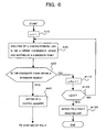
- predetermined control objects are preset as shown in a flowchart of Fig. 5 .
- the output of a target value e.g., the target dot diameter ⁇ P in this example
- a target value e.g., the target dot diameter ⁇ P in this example
- step S20 the present printing conditions (material information such as paper kind, ink kind, etc., and production information such as a planned number of prints, etc.) are collected from the production management server 31.
- predetermined printing-quality information e.g., the dot diameter ⁇ in this example
- various kinds of mechanical information such as an ink supply, a dampening water supply, etc.
- step S40 it is decided whether or not the difference ⁇ ⁇ is equal to or greater than an allowable value H. If the difference ⁇ ⁇ is less than the allowable value H, the control process advances to step S60 through NO route.
- step S60 the present printing conditions, quality information, and mechanical information collected in step S20 are correlated and stored in the database 33a, and the control process ends. Note that the allowable value H, along with the target dot diameter ⁇ P , is output in step S10 from the production management server 31 to the printing operation support unit 33.
- step S50 if the difference ⁇ ⁇ is equal to or greater than the allowable value H, the control process advances to step S50 through YES route, in which a control quantity is set.
- step A20 second and third steps
- one or more control objects e.g., the ink supply I and dampening water supply W in this example
- step A20 second and third steps
- one or more control objects e.g., the ink supply I and dampening water supply W in this example
- step A20 second and third steps
- an n-order coordinate space S 1 e.g., the first-order coordinate space in this example
- an evaluation parameter e.g., the dot diameter ⁇ in this example
- the data sets d 1 , d 2 , d 3 , ⁇ under the printing conditions nearly equal to the present printing conditions detected in step S20 of Fig. 5 are collected from among the data sets stored in the database 33a (for instance, if an a-kind of paper and a b-kind of ink are presently being used, data sets corresponding to the a-kind of paper and b-kind of ink are collected).
- the data sets d 1 , d 2 , d 3 , ⁇ are marked on the first-order coordinate space S 1 , and a characteristic straight line A for a control quantity is set.
- a control point X, on the characteristic straight line A and at a target quality value (target dot diameter ⁇ P in this example), is treated as a candidate point.
- step A30 it is decided whether or not the candidate point X is within the standard operating range R 1 . If the candidate point X is within the standard operating range R 1 , as shown in Fig. 4A , it is assumed that there is no fear that even if a control point for the printer 31 is shifted to the candidate point X, the printer 31 will be overloaded.
- step A40 the coordinate values corresponding to the control point X are set as the set values of the ink supply I and dampening water supply W.
- step A30 when it is decided that the candidate point X is outside the standard operating range R 1 , as shown in Fig. 4B , the control process advances to step A110.
- a control point X' within the standard operating range R 1 is regarded as a temporary changing point.
- step A120 it is decided whether or not the variable n is 3 or more. If it is less than 3, the control process advances to step A20.
- step A20 control objects whose priority order is the second highest in the control group (the ink temperature T and printing pressure P in this example) are selected and an n-order (second-order) coordinate space S 2 is set.
- a characteristic straight line V B is determined.
- a candidate point Y is determined while setting a changing point X' so that the sum total of the control quantities of the ink supply I, the dampening water supply W, and the ink temperature T, and printing pressure p becomes the minimum.
- step A 30 when it is decided that the candidate point Y is within the standard operating range R 2 , the control process advances to step A40.
- step A40 the coordinate values corresponding to the candidate points X' and Y are set as the set values of the ink supply I, dampening water supply W, ink temperature T, and printing pressure P.
- the control process advances to step S60 of the flowchart of Fig. 5 and ends. These set values are output to the printer control unit 32, and the control quantities of the control objects are actually preset.
- step A120 if the variable n is equal to or greater than 3, the control process advances to step A130.
- step A130 notice is issued to the fault analysis unit 5, and operation support ends forcibly.
- suppression factors are set according to the object of supporting operation, and control objects whose effect of suppressing a suppression factor is high are selected beforehand as a control group. Furthermore, the control objects in the control group are preferentially preset in the order that the effect of suppressing a suppression factor is higher. As a result, there is an advantage that the suppressing of a suppression factor and accordingly operation support can be efficiently performed.
- a control quantity is controlled based on the characteristic straight line that represents the overall distributed characteristic of a characteristic population consisting of a plurality of values measured.
- the control-quantity setting line that is set based on the measured values is optimized according to the individual characteristic and secular change of a printer. Consequently, there is an advantage that the operation support control itself is optimized according to the individual characteristic and secular change of a printer.
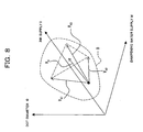
- a control object when the characteristic straight line for a control quantity does not reach a target value within the standard operating range, a control object is changed.
- control can be performed as shown in a coordinate space (represented by a W- ⁇ coordinate plane) of Fig. 7 . That is, if a control object (e.g., the dampening water supply W in this embodiment) is controlled along the characteristic straight line A 1 so that an evaluation parameter (e.g., the dot diameter ⁇ in this embodiment) reaches a target dot diameter ⁇ P , the control point will be outside the standard operating range R 1 . For this reason, the control point on characteristic straight line A 1 is set as a relay point Z so that within the standard operating range R 1 , the dot diameter ⁇ is as close to the target dot diameter ⁇ P as possible.
- a control object e.g., the dampening water supply W in this embodiment
- an evaluation parameter e.g., the dot diameter ⁇ in this embodiment
- a control point within the standard operating range R 1 and corresponding to the target dot diameter ⁇ P , is set as a target point X.
- the target point X is selected so that the total varied quantity ⁇ of the dampening water supply W and dot diameter I between the relay point Z and the target point X becomes the minimum.
- Such control can be performed with stability, because a control point is set within the standard operating range R 1 .
- the ink temperature T and printing pressure P are further preset.
- the set values of the dampening water supply W, ink supply I, ink temperature T, and printing pressure P are first determined by the printing support device 33 and then these set values are output to the printer control unit 32. At the same time, the control quantities are varied.
- the control quantities may be varied by gradually varying a combination of these control objects within the control group until the dot diameter reaches a target value. For instance, after the ink temperature T and the printing pressure P are preset in combination with each other, the dampening water supply W and the ink temperature T may be preset at the same time in combination with each other.
- the characteristic population D is elliptical in shape, as shown in Fig. 3 .
- a single representative principal axis component can be specified as the characteristic straight line A for a control quantity.
- a control-quantity vector V A can be determined in the following manner.
- control-quantity vectors V A1 , V A2 , and V A3 with respect to the principal axis components are first determined from these principal axis components and the contribution ratios, and then the total of the control-quantity vectors V A1 , V A2 , and V A3 is determined as a final control-quantity vector V A .
- the characteristic line (principal axis component) in the preferred embodiment is set as a straight line, it is suitably set according to the distributed state of the characteristic population D and therefore there are cases where it is set as a curved line.
Landscapes
- Inking, Control Or Cleaning Of Printing Machines (AREA)
Claims (7)
- Unité de support opérationnelle pour établir automatiquement des grandeurs de commande d'objets de commande pour des unités constitutives d'une imprimante (31) selon l'objet d'une opération de support, sur la base de conditions d'impression pour ladite imprimante (31), d'informations concernant la qualité de l'impression sur une copie d'impression, et d'informations mécaniques concernant ladite imprimante (31), et délivrer ensuite en sortie les grandeurs de commande établies à une unité (32) de commande d'imprimante qui commande le fonctionnement des objets de commande de ladite imprimante (31), ladite unité de support opérationnelle comprenant :un moyen d'affectation (33b) destiné à établir un ou plusieurs facteurs de suppression, qui sont des facteurs qui devraient être supprimés afin de réaliser l'objet de l'opération de support, et un paramètre d'évaluation, qui représente le degré de chacun des facteurs de suppression, et sélectionner ensuite, en tant qu'un groupe de commande, parmi les objets de commande un groupe d'objets de commande qui sont effectifs pour la suppression des facteurs de suppression;un moyen de stockage d'informations (33a) dans lequel les conditions d'impression, les informations concernant la qualité de l'impression, les informations mécaniques, et le paramètre d'évaluation sont corrélés et stockés comme une séquence d'ensembles de données ;un moyen de collecte d'informations (33c) pour collecter un ensemble de données dont les conditions d'impression coïncident essentiellement avec les conditions d'impression actuelles, à partir de la séquence d'ensembles de données stockée dans ledit moyen de stockage d'informations (33a) ; et caractérisé par le fait de comprendreun moyen d'établissement de grandeurs de commande (33d) destiné à établir, pour chacun des facteurs de suppression, les grandeurs de commande des objets de commande sélectionnés selon le paramètre d'évaluation, sur la base de la ligne caractéristique (A) afin de supprimer chacun des facteurs de suppression, où la ligne caractéristique (A) est une composante d'axe principal représentant la caractéristique de distribution de la population caractéristique (D, E) des ensembles de données collectés par ledit moyen de collecte d'informations (33c) marqués sur un espace de coordonnées (S1) ayant un paramètre d'évaluation correspondant et les objets de commande comme axes de coordonnées.
- Unité de support opérationnelle selon la revendication 1, dans laquelle ledit moyen d'établissement de grandeurs de commande (33d) établit une gamme opérationnelle standard pour chacun des objets de commande sélectionnés et établit la grandeur de commande à l'intérieur de la gamme opérationnelle standard.
- Unité de support opérationnelle selon la revendication 2, dans laquelle
le moyen d'affectation (33b) donne les ordres de priorité à la pluralité d'objets de commande sélectionnés du groupe de commande dans l'ordre dans lequel l'effet de suppression dudit facteur de suppression soit plus élevé ; et
le moyen d'établissement de grandeurs (33d) établit dans la gamme opérationnelle standard une grandeur de commande pour un objet de commande dont l'ordre de priorité est plus élevé, sur la base de la ligne caractéristique et, lorsque la grandeur de commande à elle seule ne peut pas supprimer ledit facteur de suppression, établit une grandeur de commande pour l'objet de commande ayant l'ordre de priorité le plus élevé suivant, sur la base de la ligne caractéristique. - Unité de support opérationnelle selon la revendication 3, dans laquelle, lorsque des grandeurs de commande pour la pluralité d'objets de commande sélectionnés dans le groupe de commande sont simultanément préétablies parce que le facteur de suppression ne peut pas être supprimé en commandant la grandeur de commande d'un seul objet de commande du groupe de commande dans la gamme opérationnelle standard, les grandeurs de commande sont établies de telle sorte que le total général de grandeurs variées des objets de commande sélectionnés qui sont simultanément préétablis devient minimal.
- Unité de support opérationnelle selon l'une quelconque des revendications 1 à 4, dans laquelle le moyen de collecte d'informations (33c) collecte un ensemble de données à partir de la pluralité d'ensembles de données stockés dans le moyen de stockage d'informations (33a), lorsqu'une condition est qu'un taux de balayage global pour une image est approximativement le même que le taux de balayage global actuel.
- Système de support opérationnel comprenant :une unité de sortie de conditions d'impression pour délivrer en sortie des conditions d'impression à une imprimante (31) ;une unité de détection de la qualité d'impression pour détecter des informations concernant la qualité de l'impression sur une copie d'impression;une unité de détection d'informations mécaniques pour détecter des informations mécaniques concernant l'imprimante (31) ;une unité (32) de commande d'imprimante pour commander le fonctionnement de divers types d'objets de commande de l'imprimante (31) ; etl'unité de support opérationnelle selon l'une quelconque des revendications 1 à 5 ;où le moyen de stockage d'informations (33a) corrèle les conditions d'impression à partir de l'unité de sortie de conditions d'impression, les informations concernant la qualité d'impression à partir de l'unité de détection de la qualité de l'impression, et les informations mécaniques à partir de l'unité de détection d'informations mécaniques et les stocke comme une séquence d'ensembles de données.
- Procédé de support opérationnel d'optimisation automatique de grandeurs de commande d'objets de commande pour des unités constitutives d'une imprimante (31), comprenant les étapes de :établir un ou plusieurs facteurs de suppression, qui sont des facteurs qui devraient être supprimés afin de réaliser l'objet de l'opération de support, et un paramètre d'évaluation, qui représente le degré de chacun des facteurs de suppression, et sélectionner ensuite, en tant qu'un groupe de commande, parmi les objets de commande un groupe d'objets de commande qui sont effectifs pour la suppression du facteur de suppression;collecter un ensemble de données dont les conditions d'impression coïncident essentiellement avec les conditions d'impression actuelles, à partir d'un grand nombre d'ensembles de données dans lequel les conditions d'impression, les informations concernant la qualité de l'impression, et les informations mécaniques sont corrélées ; et caractérisé par le faitd'établir, pour chacun des facteurs de suppression, les grandeurs de commande des objets de commande sélectionnés selon le paramètre d'évaluation, sur la base de la ligne caractéristique (A) afin de supprimer chacun des facteurs de suppression, où la ligne caractéristique (A) est une composante d'axe principal représentant la caractéristique de distribution de la population caractéristique (D, E) des ensembles de données collectés par ledit moyen de collecte d'informations (33c) marqués sur un espace de coordonnées (S1) ayant un paramètre d'évaluation correspondant et les objets de commande comme axes de coordonnées.
Applications Claiming Priority (2)
| Application Number | Priority Date | Filing Date | Title |
|---|---|---|---|
| JP2001203947 | 2001-07-04 | ||
| JP2001203947A JP3556927B2 (ja) | 2001-07-04 | 2001-07-04 | 印刷機の運転支援装置及び印刷機の運転支援システム並びに印刷機の運転支援方法 |
Publications (2)
| Publication Number | Publication Date |
|---|---|
| EP1273443A1 EP1273443A1 (fr) | 2003-01-08 |
| EP1273443B1 true EP1273443B1 (fr) | 2008-10-15 |
Family
ID=19040497
Family Applications (1)
| Application Number | Title | Priority Date | Filing Date |
|---|---|---|---|
| EP02014091A Expired - Lifetime EP1273443B1 (fr) | 2001-07-04 | 2002-07-02 | Unité de support, système de support et procédé de support pour un dispositif d'impresssion |
Country Status (4)
| Country | Link |
|---|---|
| US (1) | US6644194B2 (fr) |
| EP (1) | EP1273443B1 (fr) |
| JP (1) | JP3556927B2 (fr) |
| DE (1) | DE60229327D1 (fr) |
Families Citing this family (7)
| Publication number | Priority date | Publication date | Assignee | Title |
|---|---|---|---|---|
| JP3449958B2 (ja) * | 2000-01-18 | 2003-09-22 | 理想科学工業株式会社 | 印刷システム、印刷方法および印刷プログラムを格納したコンピュータ読取り可能な記録媒体 |
| US20050137833A1 (en) * | 2003-12-18 | 2005-06-23 | Rajasekhar Sistla | Automatic sensor integration |
| JP2008006632A (ja) * | 2006-06-28 | 2008-01-17 | Komori Corp | 紙流れ調整装置および方法 |
| DE102008013744A1 (de) * | 2007-04-02 | 2008-10-09 | Heidelberger Druckmaschinen Ag | Verbessertes Kennlinienlernen in Druckmaschinen |
| DE102008049355A1 (de) | 2008-09-29 | 2010-04-01 | Manroland Ag | Offsetdruckmaschine |
| US20110153374A1 (en) * | 2009-08-31 | 2011-06-23 | Usingmiles, Inc. | Reward travel management software and methods |
| CN116277952B (zh) * | 2023-04-07 | 2023-11-17 | 苏州壹哲智能科技有限公司 | 一种3d打印设备、方法、装置及介质 |
Family Cites Families (12)
| Publication number | Priority date | Publication date | Assignee | Title |
|---|---|---|---|---|
| JPH04221642A (ja) | 1990-12-21 | 1992-08-12 | Komori Corp | 多色印刷機の制御装置 |
| JPH0557879A (ja) | 1991-08-30 | 1993-03-09 | Hamada Insatsu Kikai Kk | オフセツト印刷機の運転制御装置 |
| DE4328026A1 (de) * | 1993-08-20 | 1995-03-09 | Roland Man Druckmasch | Kommunikationsverfahren und -system zum computerunterstützten Drucken |
| JPH07164619A (ja) | 1993-12-17 | 1995-06-27 | Meidensha Corp | 印刷機制御装置 |
| US5652831A (en) * | 1996-02-01 | 1997-07-29 | Industrial Technology Reasearch Institute | Variable point interpolation apparatus and method with scalable architecture for color correction |
| JPH1016193A (ja) * | 1996-06-27 | 1998-01-20 | Komori Corp | インキ膜厚の制御方法 |
| US6024018A (en) * | 1997-04-03 | 2000-02-15 | Intex Israel Technologies Corp., Ltd | On press color control system |
| DE19822662C2 (de) | 1998-05-20 | 2003-12-24 | Roland Man Druckmasch | Verfahren zur Farbreproduktion auf einer Bilddaten orientierten Druckmaschine |
| JP2000071424A (ja) * | 1998-09-02 | 2000-03-07 | Komori Corp | 多色印刷機におけるインキ膜厚制御方法 |
| JP3339835B2 (ja) * | 1999-03-10 | 2002-10-28 | リョービ株式会社 | 印刷機のインキ供給制御装置及びインキ供給制御方法 |
| US6441914B1 (en) * | 1999-10-08 | 2002-08-27 | Creoscitex Corporation Ltd. | Prediction and prevention of offset printing press problems |
| US6412412B1 (en) * | 2000-03-24 | 2002-07-02 | Heidelberger Druckmaschinen Ag | Device and method for controlling ink keys |
-
2001
- 2001-07-04 JP JP2001203947A patent/JP3556927B2/ja not_active Expired - Fee Related
-
2002
- 2002-07-01 US US10/184,924 patent/US6644194B2/en not_active Expired - Fee Related
- 2002-07-02 DE DE60229327T patent/DE60229327D1/de not_active Expired - Fee Related
- 2002-07-02 EP EP02014091A patent/EP1273443B1/fr not_active Expired - Lifetime
Also Published As
| Publication number | Publication date |
|---|---|
| DE60229327D1 (de) | 2008-11-27 |
| JP2003011331A (ja) | 2003-01-15 |
| US6644194B2 (en) | 2003-11-11 |
| US20030049064A1 (en) | 2003-03-13 |
| EP1273443A1 (fr) | 2003-01-08 |
| JP3556927B2 (ja) | 2004-08-25 |
Similar Documents
| Publication | Publication Date | Title |
|---|---|---|
| EP0881076B2 (fr) | Système de commande des vis de réglage du débit d'encre dans une machine d'impression | |
| US7548326B2 (en) | Method of adjusting image recording apparatus for correcting skew | |
| EP1464493B2 (fr) | Machine à imprimer | |
| EP1273443B1 (fr) | Unité de support, système de support et procédé de support pour un dispositif d'impresssion | |
| CN114598780A (zh) | 图像检查装置以及位置偏移测定方法 | |
| US20080204771A1 (en) | Continuous calibration of proof printer | |
| CN112644171B (zh) | 用于打印头中的墨滴体积的闭环调节的系统和方法 | |
| JP7457716B2 (ja) | 印刷システムで使用するための印刷媒体のプロファイリング方法 | |
| WO2003053706A1 (fr) | Support imprime a l'aide d'un localisateur d'image solidaire et procede associe | |
| US8300289B2 (en) | Method for compensating for color variations across a printed page using multiple-pass printing | |
| EP4029697B1 (fr) | Procédé d'estimation, procédé d'impression et imprimante | |
| US7310107B2 (en) | Method for monitoring image calibration | |
| US7570393B2 (en) | Method for calibration of a printer | |
| CN111421955B (zh) | 胶版印刷中的着色补偿 | |
| US20190384550A1 (en) | Methods, systems and devices for automated cost based color profiling of inkjet printers | |
| US12083808B2 (en) | Method for printing a print job with a printing machine | |
| CN116494645B (zh) | 用于适配多色印刷产品的Lab额定色值的方法 | |
| US11093808B2 (en) | Color matching method, and recording medium having color matching program recorded thereon | |
| EP3495150B1 (fr) | Procédé de correction de tension de tête pour appareil d'impression à jet d'encre, appareil utilisant ce dernier et programme correspondant | |
| JP4395287B2 (ja) | インキキーのプリセット装置 | |
| CA2107431A1 (fr) | Appareil servant a l'evaluation de donnees sur la couleur, et methode connexe | |
| JP2008242080A (ja) | 写真プリントシステム及び写真プリント装置の管理方法 | |
| JP2008044276A (ja) | 補正値の設定方法、補正値設定システム、及び、プログラム | |
| JP2008044275A (ja) | 補正値の設定方法、補正値設定システム、及び、プログラム |
Legal Events
| Date | Code | Title | Description |
|---|---|---|---|
| PUAI | Public reference made under article 153(3) epc to a published international application that has entered the european phase |
Free format text: ORIGINAL CODE: 0009012 |
|
| AK | Designated contracting states |
Kind code of ref document: A1 Designated state(s): AT BE BG CH CY CZ DE DK EE ES FI FR GB GR IE IT LI LU MC NL PT SE SK TR |
|
| AX | Request for extension of the european patent |
Free format text: AL;LT;LV;MK;RO;SI |
|
| 17P | Request for examination filed |
Effective date: 20030130 |
|
| AKX | Designation fees paid |
Designated state(s): BE DE FR GB IT |
|
| 17Q | First examination report despatched |
Effective date: 20051230 |
|
| GRAP | Despatch of communication of intention to grant a patent |
Free format text: ORIGINAL CODE: EPIDOSNIGR1 |
|
| GRAS | Grant fee paid |
Free format text: ORIGINAL CODE: EPIDOSNIGR3 |
|
| GRAA | (expected) grant |
Free format text: ORIGINAL CODE: 0009210 |
|
| AK | Designated contracting states |
Kind code of ref document: B1 Designated state(s): BE DE FR GB IT |
|
| REG | Reference to a national code |
Ref country code: GB Ref legal event code: FG4D |
|
| REF | Corresponds to: |
Ref document number: 60229327 Country of ref document: DE Date of ref document: 20081127 Kind code of ref document: P |
|
| PG25 | Lapsed in a contracting state [announced via postgrant information from national office to epo] |
Ref country code: BE Free format text: LAPSE BECAUSE OF FAILURE TO SUBMIT A TRANSLATION OF THE DESCRIPTION OR TO PAY THE FEE WITHIN THE PRESCRIBED TIME-LIMIT Effective date: 20081015 |
|
| PLBE | No opposition filed within time limit |
Free format text: ORIGINAL CODE: 0009261 |
|
| STAA | Information on the status of an ep patent application or granted ep patent |
Free format text: STATUS: NO OPPOSITION FILED WITHIN TIME LIMIT |
|
| PG25 | Lapsed in a contracting state [announced via postgrant information from national office to epo] |
Ref country code: IT Free format text: LAPSE BECAUSE OF FAILURE TO SUBMIT A TRANSLATION OF THE DESCRIPTION OR TO PAY THE FEE WITHIN THE PRESCRIBED TIME-LIMIT Effective date: 20081015 |
|
| 26N | No opposition filed |
Effective date: 20090716 |
|
| PGFP | Annual fee paid to national office [announced via postgrant information from national office to epo] |
Ref country code: DE Payment date: 20090626 Year of fee payment: 8 |
|
| GBPC | Gb: european patent ceased through non-payment of renewal fee |
Effective date: 20090702 |
|
| REG | Reference to a national code |
Ref country code: FR Ref legal event code: ST Effective date: 20100331 |
|
| PG25 | Lapsed in a contracting state [announced via postgrant information from national office to epo] |
Ref country code: FR Free format text: LAPSE BECAUSE OF NON-PAYMENT OF DUE FEES Effective date: 20090731 |
|
| PG25 | Lapsed in a contracting state [announced via postgrant information from national office to epo] |
Ref country code: GB Free format text: LAPSE BECAUSE OF NON-PAYMENT OF DUE FEES Effective date: 20090702 |
|
| PG25 | Lapsed in a contracting state [announced via postgrant information from national office to epo] |
Ref country code: DE Free format text: LAPSE BECAUSE OF NON-PAYMENT OF DUE FEES Effective date: 20110201 |
|
| REG | Reference to a national code |
Ref country code: DE Ref legal event code: R119 Ref document number: 60229327 Country of ref document: DE Effective date: 20110201 |