EP1271577A1 - Haltevorrichtung für ein elektronisches Bauelement - Google Patents
Haltevorrichtung für ein elektronisches Bauelement Download PDFInfo
- Publication number
- EP1271577A1 EP1271577A1 EP01810570A EP01810570A EP1271577A1 EP 1271577 A1 EP1271577 A1 EP 1271577A1 EP 01810570 A EP01810570 A EP 01810570A EP 01810570 A EP01810570 A EP 01810570A EP 1271577 A1 EP1271577 A1 EP 1271577A1
- Authority
- EP
- European Patent Office
- Prior art keywords
- leg
- holding device
- surface part
- wall
- component
- Prior art date
- Legal status (The legal status is an assumption and is not a legal conclusion. Google has not performed a legal analysis and makes no representation as to the accuracy of the status listed.)
- Granted
Links
Images



Classifications
-
- H—ELECTRICITY
- H05—ELECTRIC TECHNIQUES NOT OTHERWISE PROVIDED FOR
- H05K—PRINTED CIRCUITS; CASINGS OR CONSTRUCTIONAL DETAILS OF ELECTRIC APPARATUS; MANUFACTURE OF ASSEMBLAGES OF ELECTRICAL COMPONENTS
- H05K7/00—Constructional details common to different types of electric apparatus
- H05K7/14—Mounting supporting structure in casing or on frame or rack
-
- H—ELECTRICITY
- H01—ELECTRIC ELEMENTS
- H01G—CAPACITORS; CAPACITORS, RECTIFIERS, DETECTORS, SWITCHING DEVICES, LIGHT-SENSITIVE OR TEMPERATURE-SENSITIVE DEVICES OF THE ELECTROLYTIC TYPE
- H01G2/00—Details of capacitors not covered by a single one of groups H01G4/00-H01G11/00
- H01G2/02—Mountings
- H01G2/04—Mountings specially adapted for mounting on a chassis
-
- H—ELECTRICITY
- H05—ELECTRIC TECHNIQUES NOT OTHERWISE PROVIDED FOR
- H05K—PRINTED CIRCUITS; CASINGS OR CONSTRUCTIONAL DETAILS OF ELECTRIC APPARATUS; MANUFACTURE OF ASSEMBLAGES OF ELECTRICAL COMPONENTS
- H05K7/00—Constructional details common to different types of electric apparatus
- H05K7/02—Arrangements of circuit components or wiring on supporting structure
Definitions
- the present invention relates to the field of electronic fastening technology Components. It relates to a holding device for at least one electronic Component according to the preamble of the independent claim.
- a such a holding device is constructed from two in the plate-shaped legs, which on one their leg ends are connected to each other. The two legs form in essentially a right angle.
- the component is usually on its electrical Connections attached to one of the legs.
- the other leg is used for attachment the holding device, for example on a frame of a converter circuit and is provided with corresponding holes.
- the problem with such a holding device is that the electronic component is connected to the holding device only at its electrical connections.
- mechanical Stresses in particular bending stresses on the component, such as they can usually prevail in a harsh environment in a converter circuit, can tear off the connections of the component and thus the component and damage or destroy the holding device.
- the assembly is for replacement and maintenance of the component in an already installed in a converter circuit Holding device very difficult because the component only on its connections to the Holding device is attachable and no other breakpoint and / or no additional Holding surface, which has a holding function of the component during assembly and could take maintenance. But this is the assembly and maintenance of the Component complex, lengthy and causes considerable costs.
- the object of the invention is therefore a holding device for at least one electronic To further develop the component in such a way that an improved fastening of the component is achieved in a circuit, in particular a converter circuit, and a particularly simple, quick and therefore inexpensive installation and maintenance of the Component is made possible.
- This object is achieved by the features of claim 1 solved.
- Advantageous developments of the invention are specified in the subclaims.
- the holding device according to the invention for at least one electronic component is from a first substantially plate-shaped leg and from a second essentially built up plate-shaped legs, the two legs on one of their Leg ends are connected to each other and to each other a substantially right Form an angle.
- the first leg and the second leg each have a leg wall facing the substantially right angle, wherein the inner leg wall of the first leg has a receiving surface for supporting a Has lateral surface part of the electronic component.
- this receiving area is advantageously given a stop, a stop line or a stop surface on which the Component can rest and thus additional support to the usual attachment of the Component at its electrical connections on one of the legs, in particular on second leg, experiences.
- the component receives through the receiving surface, for example an improved fixation in a converter circuit. Furthermore, that must Component placed only on the receiving surface for assembly and / or maintenance purposes and can then be very easily and quickly connected to its electrical connections are attached so that cost-effective maintenance and / or assembly is achieved can be.
- the inner leg wall of the second leg has according to the invention at least one pressing surface for the area contacting of an electrical connection comprehensive surface part of the component.
- the inventive 1a is a spatial representation of a first embodiment of an inventive one Holding device for at least one electrical component 1, in particular for a power resistor or capacitor.
- the electronic component 1 is not shown in FIG. 1a for the sake of clarity.
- the inventive 1a is made of a first leg 2 and a second Leg 3 built.
- the first leg 2 and the second leg 3 are essentially plate-shaped, the two legs 2, 3 at one of their leg ends are interconnected.
- the two legs 2, 3 are arranged such that they form a substantially right angle to each other.
- the first leg 2 and the second leg 3 each have one substantially right angle facing inner leg wall 4, 5, wherein the Inner leg wall 4 of the first leg 2 has a receiving surface 6 for supporting a Has lateral surface part of the electronic component 1.
- the receiving surface 6 provides advantageously a stop or a holding surface for the electronic component 1 represents on which the component 1 can rest.
- the receiving surface 6 offers that Component 1 thus provides additional support to the conventional one known from the prior art Attachment at its electrical connections to one of the legs 2, 3, in particular on the second leg 3.
- Fig. 1b is a sectional view along Ib-Ib of the first embodiment of the holding device shown in Fig. 1a.
- the second leg 3 according to FIG Fig. 1a and Fig. 1b on its inner leg wall 5 at least one pressing surface 7 for flat Contacting a surface part comprising an electrical connection of the component 1.
- the component 1 is with the surface part through the attachment at its electrical connections on the second leg 2 against the pressing surface 7 pressed so that the component 1 is additionally fixed under mechanical loads can be, since there is almost no play between the pressing surface 7 and the surface part of the component with the electrical connections.
- the electrical are advantageous Connections of the component 1 are relieved, thereby reducing the service life of the component 1 and the holding device can be enlarged, since the holding device and the component 1 is damaged or even less frequently by tearing off the electrical connections be destroyed.
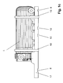
- FIG. 1c is a front view of the first embodiment of the holding device according to FIG Fig. 1a shown, in Fig. 1c additionally for the electronic component 1 as an example a power resistor is shown.
- the inner leg wall 4 of the first leg 2 an edge region 9, the receiving surface 6 to extends the edge region 9.
- the edge region 9 extends from the receiving surface 9 to the edge of the first leg 2.
- this edge area 9 are perpendicular to the inner leg wall 4 of the first leg 2 at least two each from the inner leg wall 4 of the first leg 2 to one of the leg inner wall 4 opposite Leg outer wall 18 of the first leg 2 extending mounting holes 8 are provided.
- these mounting holes 8 it is possible to make the holding device very simple to be mounted on a frame, for example a converter circuit.
- Another improvement to the mounting of the holding device on a frame Converter circuit can be achieved by connecting the first Leg 2 with the second leg 3 one with respect to the first leg 2 in the opposite Extension plate 17 extending in alignment is arranged, wherein at least one further mounting hole 8 running perpendicularly through the extension plate 17 is provided, on which the holding device can be additionally attached.
- the receiving surface 6 also has a first surface part 6a and a second surface part 6b, the two surface parts 6a, 6b each extend essentially in a partial surface course direction X.
- the direction of the partial surface is X is defined as the direction from the connection of the first Leg 2 with the second leg 3 to the opposite leg end in alignment of the first leg 1 shows, as shown in Fig. 1a.
- the first surface part 6a and the second surface part rise to the surface part course direction X.
- 6b according to FIG. 1a roof-like up to the edge area 9, with the two surface parts 6a, 6b are opposite. This gives cylindrical components 1 with a essentially circular cross-section, as shown in Fig.
- the receiving surface 6 according to FIG. 1a has a third surface part 6c, which is in the essentially in the surface partial course direction X defined above between the first Surface part 6a and the second surface part 6b extends.
- first surface part 6a and the second surface part 6b have the receiving surface 6 according to FIG. 1a according to the invention perpendicular to the direction of the partial surface course X extending grooves 11.
- a groove 11 lies in each case in a groove 11 of the first surface part 6a of the second surface part 6b in alignment.
- opposite grooves 11 may, for the sake of clarity, distance elements not shown in FIG Size of the component 1 are inserted, the slipping of the component 1st in the direction of the partial surface course X and at the same time ensure that the Component 1 is pressed further against the pressing surface 7.
- Fig. 2a is a spatial partial section of a second embodiment of the Holding device according to the invention shown for at least one electrical component 1, which differ from the first embodiment according to the invention described above 1a, 1b and 1c differs in that the second Leg 3 a substantially from the connection of the first leg 2 with the second leg 3 to the flush opposite leg end of the second leg 3 extending recess 12.
- the recess 12 is designed to carry out the inner leg wall 5 of the second leg 3 to one opposite the inner leg wall 5 Leg outer wall 13 of the second leg 3 formed and divides the second leg 3 according to FIG. 2a in two partial legs 3a, 3b.
- connection cable fastening device 20 which on the the side of the extension plate 17 facing the second leg 3 is provided.
- connection cable fastening device 20 formed tab-shaped, so that the connection cable with lashing straps, in particular cable ties, through the connecting cable fastening device 20 are looped on the connection cable fastening device 20 can be tied.
- the receiving device 15 has a wall along the outer leg 13a, 13b of the associated partial leg 3a, 3b until the connection of the first Leg 2 with the respective partial leg 3a, 3b extending recess 16.
- the recess 16 is preferably open towards the cutout 12, so that the component holding rail 19 can be inserted into the respective recess and without further attachment gets along.
- the power capacitor is also looped through the holes 10 and cable ties laid and tied around the power capacitor pressed against the receiving surface 6.
- the power capacitor is one of its electrical Connections connected to the component holding rail 19 and thus receives advantageous additional hold.
- the holding device according to the invention can advantageously have several record electronic components 1, in particular power capacitors, wherein the electronic components lie in series on the receiving surface and preferably each with lashing straps, in particular cable ties, in the above Are pressed against the receiving surface 6.
- the holding device according to the invention is advantageously made of a castable insulation material built up, whereby the two legs 2, 3 and the other described above Components of the holding device can be easily implemented without machining such as milling and / or grinding is necessary.
- the holding device according to the invention is an improved fastening of the electronic component 1 in a circuit, in particular a converter circuit achievable, while also a particularly simple, fast and therefore inexpensive Assembly and maintenance of the component 1 can be achieved.
Landscapes
- Engineering & Computer Science (AREA)
- Microelectronics & Electronic Packaging (AREA)
- Power Engineering (AREA)
- Mounting Components In General For Electric Apparatus (AREA)
- Insertion, Bundling And Securing Of Wires For Electric Apparatuses (AREA)
- Details Of Resistors (AREA)
Abstract
Description
- Fig. 1 a
- eine räumliche Darstellung einer ersten Ausführungsform einer erfindungsgemässen Haltevorrichtung für mindestens ein elektrisches Bauelement,
- Fig. 1b
- eine Schnittdarstellung entlang Ib-Ib der ersten Ausführungsform der Haltevorrichtung gemäss Fig. 1a,
- Fig. 1c
- eine Vorderansicht der ersten Ausführungsform der Haltevorrichtung gemäss Fig. 1a,
- Fig. 2a
- eine räumliche Teilausschnittdarstellung einer zweiten Ausführungsform der erfindungsgemässen Haltevorrichtung für mindestens ein elektrisches Bauelement und
- Fig. 2b
- eine Vorderansicht der zweiten Ausführungsform der Haltevorrichtung gemäss Fig. 2a.
- 1
- elektronisches Bauelement
- 2
- erster Schenkel
- 3
- zweiter Schenkel
- 3a, 3b
- Teilschenkel
- 4
- Schenkelinnenwand des ersten Schenkels
- 5
- Schenkelinnenwand des zweiten Schenkels
- 6
- Aufnahmefläche
- 6a
- erstes Flächenteil
- 6b
- zweites Flächenteil
- 6c
- drittes Flächenteil
- 7
- Pressfläche
- 8
- Montageloch
- 9
- Randbereich
- 10
- Löcher
- 11
- Nut
- 12
- Aussparung
- 13
- Schenkelaussenwand des zweiten Schenkels
- 13a, 13b
- Schenkelaussenwand des Teilschenkels
- 14
- Element
- 15
- Aufnahmeeinrichtung
- 16
- Vertiefung
- 17
- Fortsatzplatte
- 18
- Schenkelaussenwand des ersten Schenkels
- 19
- Bauteilhalteschiene
- 20
- Anschlusskabelbefestigungseinrichtung
Claims (15)
- Haltevorrichtung für mindestens ein elektronisches Bauelement (1), die aus einem ersten im wesentlichen plattenförmigen Schenkel (2) und aus einem zweiten im wesentlichen plattenförmigen Schenkel (3) aufgebaut ist, wobei die beiden Schenkel (2; 3) an einem ihrer Schenkelenden miteinander verbunden sind und zueinander einen im wesentlichen rechten Winkel bilden, dadurch gekennzeichnet, dass der erste Schenkel (2) und der zweite Schenkel (3) jeweils eine dem im wesentlichen rechten Winkel zugewandte Schenkelinnenwand (4; 5) aufweisen, dass die Schenkelinnenwand (4) des ersten Schenkels (2) eine Aufnahmefläche (6) zur Auflage eines Mantelflächenteils des elektronischen Bauelementes (1) aufweist, und dass die Schenkelinnenwand (5) des zweiten Schenkels (3) mindestens eine Pressfläche (7) zur flächigen Kontaktierung eines einen elektrischen Anschluss umfassenden Oberflächenteils des Bauelementes (1) aufweist.
- Haltevorrichtung nach Anspruch 1, dadurch gekennzeichnet, dass an der Verbindung des ersten Schenkels (2) mit dem zweiten Schenkel (3) eine sich bezüglich des ersten Schenkels (1) in entgegengesetzter Richtung fluchtend erstreckende Fortsatzplatte (17) angeordnet ist, wobei mindestens ein senkrecht durch die Fortsatzplatte (17) verlaufendes Montageloch (8) vorgesehen ist.
- Haltevorrichtung nach Anspruch 2, dadurch gekennzeichnet, dass auf der dem zweiten Schenkel (3) zugewandten Seite der Fortsatzplatte (17) eine Anschlusskabelbefestigungseinrichtung (20) vorgesehen ist.
- Haltevorrichtung nach einem der Ansprüche 1 bis 3, dadurch gekennzeichnet, die Schenkelinnenwand (4) des ersten Schenkels (2) einen Randbereich (9) aufweist und dass sich die Aufnahmefläche (6) bis an den Randbereich (9) erstreckt.
- Haltevorrichtung nach Anspruch 4, dadurch gekennzeichnet, dass im Randbereich (9) senkrecht zur Schenkelinnenwand (4) des ersten Schenkels (2) mindestens zwei jeweils von der Schenkelinnenwand (4) des ersten Schenkels (2) zu einer Schenkelaussenwand (18) des ersten Schenkels (2) verlaufende Löcher (10) vorgesehen sind.
- Haltevorrichtung nach Anspruch 4, dadurch gekennzeichnet, dass im Randbereich (9) senkrecht zur Schenkelinnenwand (4) des ersten Schenkels (2) mindestens zwei jeweils von der Schenkelinnenwand (4) des ersten Schenkels (2) zu einer Schenkelaussenwand (18) des ersten Schenkels (2) Montagelöcher (8) vorgesehen sind.
- Haltevorrichtung nach Anspruch 4, dadurch gekennzeichnet, dass die Aufnahmefläche (6) einen ersten Flächenteil (6a) und einen zweiten Flächenteil (6b) aufweist, und dass sich die beiden Flächenteile (6a; 6b) jeweils im wesentlichen in einer Flächenteilverlaufsrichtung (X) erstrecken, wobei die Flächenteilverlaufsrichtung (X) als Richtung definiert ist, welche von der Verbindung des ersten Schenkels (2) mit dem zweiten Schenkel (3) zum fluchtend gegenüberliegenden Schenkelende des ersten Schenkels (2) zeigt.
- Haltevorrichtung nach Anspruch 7, dadurch gekennzeichnet, dass der erste Flächenteil (6a) und der zweite Flächenteil (6b) senkrecht zur Flächenteilverlaufsrichtung (X) dachartig bis zum Randbereich (9) hin ansteigen.
- Haltevorrichtung nach Anspruch 7 oder 8, dadurch gekennzeichnet, dass der erste Flächenteil (6a) und der zweite Flächenteil (6b) senkrecht zur Flächenteilverlaufsrichtung (X) verlaufende Nuten (11) aufweisen.
- Haltevorrichtung nach Anspruch 9, dadurch gekennzeichnet, dass jeweils einer Nut (11) des ersten Flächenteils (6a) eine Nut (11) des zweiten Flächenteils (6b) fluchtend gegenüberliegt.
- Haltevorrichtung nach einem der Ansprüche 7 bis 10, dadurch gekennzeichnet, dass die Aufnahmefläche (6) einen dritten Flächenteil (6c) aufweist, der sich im wesentlichen in Flächenteilverlaufsrichtung (X) zwischen dem ersten Flächenteil (6a) und dem zweiten Flächenteil (6b) erstreckt.
- Haltevorrichtung nach einem der vorhergehenden Ansprüche, dadurch gekennzeichnet, dass der zweite Schenkel (3) eine sich im wesentlichen von der Verbindung des ersten Schenkels (2) mit dem zweiten Schenkel (3) zum fluchtend gegenüberliegenden Schenkelende des zweiten Schenkels (3) erstreckende Aussparung (12) aufweist.
- Haltevorrichtung nach Anspruch 12, dadurch gekennzeichnet, dass die Aussparung (12) als Durchführung von der Schenkelinnenwand (5) des zweiten Schenkels (3) zu einer Schenkelaussenwand (13) des zweiten Schenkels (3) ausgebildet ist und den zweiten Schenkel (3) in zwei Teilschenkel (3a; 3b) aufteilt.
- Haltevorrichtung nach Anspruch 13, dadurch gekennzeichnet, dass an einer Schenkelaussenwand (13a; 13b) eines jeden Teilschenkels (3a; 3b) ein Element (14) vorgesehen ist, das mit einem Teil der Schenkelaussenwand (13a; 13b) des zugehörigen Teilschenkels (3a; 3b) eine Aufnahmeeinrichtung (15) für eine Bauelementhalteschiene (19) bildet.
- Haltevorrichtung nach Anspruch 14, dadurch gekennzeichnet, dass die Aufnahmeeinrichtung (15) eine längs der Schenkelaussenwand (13a; 13b) des zugehörigen Teilschenkels (3a; 3b) bis zur Verbindung des ersten Schenkels (2) mit dem jeweiligen Teilschenkel (3a; 3b) verlaufende Vertiefung (16) aufweist, wobei die Vertiefung (16) zur Aussparung (12) hin offen ist.
Priority Applications (6)
| Application Number | Priority Date | Filing Date | Title |
|---|---|---|---|
| DE50108747T DE50108747D1 (de) | 2001-06-13 | 2001-06-13 | Haltevorrichtung für ein elektronisches Bauelement |
| EP01810570A EP1271577B1 (de) | 2001-06-13 | 2001-06-13 | Haltevorrichtung für ein elektronisches Bauelement |
| KR1020020030134A KR100867917B1 (ko) | 2001-06-13 | 2002-05-30 | 전자 부품용 보유 장치 |
| US10/162,629 US6663418B2 (en) | 2001-06-13 | 2002-06-06 | Holding device for an electronic component |
| JP2002168068A JP2003060364A (ja) | 2001-06-13 | 2002-06-10 | 電子部品のための保持装置 |
| CA002390297A CA2390297C (en) | 2001-06-13 | 2002-06-11 | Holding device for an electronic component |
Applications Claiming Priority (1)
| Application Number | Priority Date | Filing Date | Title |
|---|---|---|---|
| EP01810570A EP1271577B1 (de) | 2001-06-13 | 2001-06-13 | Haltevorrichtung für ein elektronisches Bauelement |
Publications (2)
| Publication Number | Publication Date |
|---|---|
| EP1271577A1 true EP1271577A1 (de) | 2003-01-02 |
| EP1271577B1 EP1271577B1 (de) | 2006-01-18 |
Family
ID=8183962
Family Applications (1)
| Application Number | Title | Priority Date | Filing Date |
|---|---|---|---|
| EP01810570A Expired - Lifetime EP1271577B1 (de) | 2001-06-13 | 2001-06-13 | Haltevorrichtung für ein elektronisches Bauelement |
Country Status (6)
| Country | Link |
|---|---|
| US (1) | US6663418B2 (de) |
| EP (1) | EP1271577B1 (de) |
| JP (1) | JP2003060364A (de) |
| KR (1) | KR100867917B1 (de) |
| CA (1) | CA2390297C (de) |
| DE (1) | DE50108747D1 (de) |
Citations (4)
| Publication number | Priority date | Publication date | Assignee | Title |
|---|---|---|---|---|
| GB826457A (en) * | 1955-03-31 | 1960-01-06 | Telefunken Gmbh | Improvements in or relating to the mounting of components on a support |
| FR2770739A1 (fr) * | 1997-11-05 | 1999-05-07 | Lacme | Appareil electrificateur de cloture |
| EP0948003A1 (de) * | 1998-04-02 | 1999-10-06 | Brökelmann, Jaeger & Busse GmbH & Co | Halterung für einen Kondensatorbecher |
| WO2001001549A1 (en) * | 1999-06-30 | 2001-01-04 | General Electric Company | Mounting bracket for motor capacitor |
Family Cites Families (3)
| Publication number | Priority date | Publication date | Assignee | Title |
|---|---|---|---|---|
| US4303296A (en) * | 1978-05-03 | 1981-12-01 | Bunker Ramo Corporation | Modular interface connector |
| JPS58135752U (ja) * | 1982-03-05 | 1983-09-12 | ティーディーケイ株式会社 | 静電式複写機用帯電装置 |
| AU9247098A (en) * | 1998-09-16 | 2000-04-03 | Luciano Da Luz Moraes | Mounting of capacitors in electrical control box |
-
2001
- 2001-06-13 EP EP01810570A patent/EP1271577B1/de not_active Expired - Lifetime
- 2001-06-13 DE DE50108747T patent/DE50108747D1/de not_active Expired - Fee Related
-
2002
- 2002-05-30 KR KR1020020030134A patent/KR100867917B1/ko not_active Expired - Fee Related
- 2002-06-06 US US10/162,629 patent/US6663418B2/en not_active Expired - Fee Related
- 2002-06-10 JP JP2002168068A patent/JP2003060364A/ja not_active Withdrawn
- 2002-06-11 CA CA002390297A patent/CA2390297C/en not_active Expired - Fee Related
Patent Citations (4)
| Publication number | Priority date | Publication date | Assignee | Title |
|---|---|---|---|---|
| GB826457A (en) * | 1955-03-31 | 1960-01-06 | Telefunken Gmbh | Improvements in or relating to the mounting of components on a support |
| FR2770739A1 (fr) * | 1997-11-05 | 1999-05-07 | Lacme | Appareil electrificateur de cloture |
| EP0948003A1 (de) * | 1998-04-02 | 1999-10-06 | Brökelmann, Jaeger & Busse GmbH & Co | Halterung für einen Kondensatorbecher |
| WO2001001549A1 (en) * | 1999-06-30 | 2001-01-04 | General Electric Company | Mounting bracket for motor capacitor |
Also Published As
| Publication number | Publication date |
|---|---|
| JP2003060364A (ja) | 2003-02-28 |
| CA2390297A1 (en) | 2002-12-13 |
| KR20020095086A (ko) | 2002-12-20 |
| CA2390297C (en) | 2009-10-06 |
| DE50108747D1 (de) | 2006-04-06 |
| US6663418B2 (en) | 2003-12-16 |
| EP1271577B1 (de) | 2006-01-18 |
| US20030003797A1 (en) | 2003-01-02 |
| KR100867917B1 (ko) | 2008-11-10 |
Similar Documents
| Publication | Publication Date | Title |
|---|---|---|
| DE19753078C2 (de) | Elektrische Anschlußklemme, insbesondere Anreihklemme | |
| EP3164911B1 (de) | Steckverbinder | |
| DE3107932C2 (de) | ||
| DE102010033808B4 (de) | Reihenklemme | |
| EP0982978A2 (de) | Gehäuse, insbesondere Schlossgehäuse mit elektrischen Anschlusseinrichtungen | |
| EP0878868B1 (de) | Anschlussklemme | |
| DE3540329A1 (de) | Aus blechteilen zusammensetzbares tragwerk | |
| CH693656A5 (de) | Isolationskamm für Multikontaktstecker. | |
| AT405354B (de) | Stromversorgungselement für leiterplatten | |
| DE19916949B4 (de) | Gehäuse, insbesondere Schloßgehäuse für einen Kraftfahrzeugtürverschluß, Getriebegehäuse oder dergleichen Leitungsträger | |
| EP1271577A1 (de) | Haltevorrichtung für ein elektronisches Bauelement | |
| WO1998044770A1 (de) | Vorrichtung zum befestigen eines schirmdeckels | |
| DE10136361A1 (de) | Anschlussvorrichtung zur elektrischen Kontaktierung einer Masseleitung mit Massepotenzial | |
| DE8422203U1 (de) | Stehbuchse | |
| DE3911108A1 (de) | Elektrische anschlussklemme fuer leiterplatten | |
| DE102016115898A1 (de) | Anordnung zur Befestigung von Leiterplatten | |
| DE3908532C2 (de) | ||
| DE69612466T2 (de) | Elektrischer Kabelsteckverbinder zum Anschliessen an ein leitendes Teil | |
| DE3831961A1 (de) | Halter fuer hybridplatten mit elektronischen bauelementen | |
| DE20104407U1 (de) | Leitungsverbinder | |
| DE19952912C2 (de) | Leiterplattenanordnung | |
| DE29709210U1 (de) | Verbindungselementekombination | |
| DE8910807U1 (de) | Steckgehäuse | |
| DE10243385B4 (de) | Stecker, insbesondere Profibus-Stecker | |
| DE4231633C1 (en) | Plug connector fixing system using mounting plate - has slits in junction zone between fixing screw bores and adjacent edge |
Legal Events
| Date | Code | Title | Description |
|---|---|---|---|
| PUAI | Public reference made under article 153(3) epc to a published international application that has entered the european phase |
Free format text: ORIGINAL CODE: 0009012 |
|
| AK | Designated contracting states |
Kind code of ref document: A1 Designated state(s): AT BE CH CY DE DK ES FI FR GB GR IE IT LI LU MC NL PT SE TR |
|
| AX | Request for extension of the european patent |
Free format text: AL;LT;LV;MK;RO;SI |
|
| 17P | Request for examination filed |
Effective date: 20030517 |
|
| AKX | Designation fees paid |
Designated state(s): CH DE FR GB LI |
|
| 17Q | First examination report despatched |
Effective date: 20050311 |
|
| GRAP | Despatch of communication of intention to grant a patent |
Free format text: ORIGINAL CODE: EPIDOSNIGR1 |
|
| GRAS | Grant fee paid |
Free format text: ORIGINAL CODE: EPIDOSNIGR3 |
|
| GRAA | (expected) grant |
Free format text: ORIGINAL CODE: 0009210 |
|
| AK | Designated contracting states |
Kind code of ref document: B1 Designated state(s): CH DE FR GB LI |
|
| PG25 | Lapsed in a contracting state [announced via postgrant information from national office to epo] |
Ref country code: GB Free format text: LAPSE BECAUSE OF FAILURE TO SUBMIT A TRANSLATION OF THE DESCRIPTION OR TO PAY THE FEE WITHIN THE PRESCRIBED TIME-LIMIT Effective date: 20060118 |
|
| REG | Reference to a national code |
Ref country code: GB Ref legal event code: FG4D Free format text: NOT ENGLISH |
|
| REG | Reference to a national code |
Ref country code: CH Ref legal event code: EP |
|
| REF | Corresponds to: |
Ref document number: 50108747 Country of ref document: DE Date of ref document: 20060406 Kind code of ref document: P |
|
| PG25 | Lapsed in a contracting state [announced via postgrant information from national office to epo] |
Ref country code: LI Free format text: LAPSE BECAUSE OF NON-PAYMENT OF DUE FEES Effective date: 20060630 Ref country code: CH Free format text: LAPSE BECAUSE OF NON-PAYMENT OF DUE FEES Effective date: 20060630 |
|
| GBV | Gb: ep patent (uk) treated as always having been void in accordance with gb section 77(7)/1977 [no translation filed] |
Effective date: 20060118 |
|
| ET | Fr: translation filed | ||
| PLBE | No opposition filed within time limit |
Free format text: ORIGINAL CODE: 0009261 |
|
| STAA | Information on the status of an ep patent application or granted ep patent |
Free format text: STATUS: NO OPPOSITION FILED WITHIN TIME LIMIT |
|
| 26N | No opposition filed |
Effective date: 20061019 |
|
| REG | Reference to a national code |
Ref country code: CH Ref legal event code: PL |
|
| PGFP | Annual fee paid to national office [announced via postgrant information from national office to epo] |
Ref country code: FR Payment date: 20090615 Year of fee payment: 9 |
|
| PGFP | Annual fee paid to national office [announced via postgrant information from national office to epo] |
Ref country code: DE Payment date: 20090622 Year of fee payment: 9 |
|
| REG | Reference to a national code |
Ref country code: FR Ref legal event code: ST Effective date: 20110228 |
|
| PG25 | Lapsed in a contracting state [announced via postgrant information from national office to epo] |
Ref country code: DE Free format text: LAPSE BECAUSE OF NON-PAYMENT OF DUE FEES Effective date: 20110101 |
|
| PG25 | Lapsed in a contracting state [announced via postgrant information from national office to epo] |
Ref country code: FR Free format text: LAPSE BECAUSE OF NON-PAYMENT OF DUE FEES Effective date: 20100630 |