EP1271013B1 - Gangwähleinrichtung für ein Handschaltgetriebe - Google Patents
Gangwähleinrichtung für ein Handschaltgetriebe Download PDFInfo
- Publication number
- EP1271013B1 EP1271013B1 EP02014191A EP02014191A EP1271013B1 EP 1271013 B1 EP1271013 B1 EP 1271013B1 EP 02014191 A EP02014191 A EP 02014191A EP 02014191 A EP02014191 A EP 02014191A EP 1271013 B1 EP1271013 B1 EP 1271013B1
- Authority
- EP
- European Patent Office
- Prior art keywords
- shifting
- speed
- arm
- selecting
- reverse
- Prior art date
- Legal status (The legal status is an assumption and is not a legal conclusion. Google has not performed a legal analysis and makes no representation as to the accuracy of the status listed.)
- Expired - Fee Related
Links
Images


Classifications
-
- F—MECHANICAL ENGINEERING; LIGHTING; HEATING; WEAPONS; BLASTING
- F16—ENGINEERING ELEMENTS AND UNITS; GENERAL MEASURES FOR PRODUCING AND MAINTAINING EFFECTIVE FUNCTIONING OF MACHINES OR INSTALLATIONS; THERMAL INSULATION IN GENERAL
- F16H—GEARING
- F16H61/00—Control functions within control units of change-speed- or reversing-gearings for conveying rotary motion ; Control of exclusively fluid gearing, friction gearing, gearings with endless flexible members or other particular types of gearing
- F16H61/18—Preventing unintentional or unsafe shift, e.g. preventing manual shift from highest gear to reverse gear
-
- F—MECHANICAL ENGINEERING; LIGHTING; HEATING; WEAPONS; BLASTING
- F16—ENGINEERING ELEMENTS AND UNITS; GENERAL MEASURES FOR PRODUCING AND MAINTAINING EFFECTIVE FUNCTIONING OF MACHINES OR INSTALLATIONS; THERMAL INSULATION IN GENERAL
- F16H—GEARING
- F16H63/00—Control outputs from the control unit to change-speed- or reversing-gearings for conveying rotary motion or to other devices than the final output mechanism
- F16H63/02—Final output mechanisms therefor; Actuating means for the final output mechanisms
- F16H63/08—Multiple final output mechanisms being moved by a single common final actuating mechanism
- F16H63/20—Multiple final output mechanisms being moved by a single common final actuating mechanism with preselection and subsequent movement of each final output mechanism by movement of the final actuating mechanism in two different ways, e.g. guided by a shift gate
-
- F—MECHANICAL ENGINEERING; LIGHTING; HEATING; WEAPONS; BLASTING
- F16—ENGINEERING ELEMENTS AND UNITS; GENERAL MEASURES FOR PRODUCING AND MAINTAINING EFFECTIVE FUNCTIONING OF MACHINES OR INSTALLATIONS; THERMAL INSULATION IN GENERAL
- F16H—GEARING
- F16H61/00—Control functions within control units of change-speed- or reversing-gearings for conveying rotary motion ; Control of exclusively fluid gearing, friction gearing, gearings with endless flexible members or other particular types of gearing
- F16H61/16—Inhibiting or initiating shift during unfavourable conditions, e.g. preventing forward reverse shift at high vehicle speed, preventing engine over speed
- F16H2061/165—Preventing reverse gear shifts if vehicle speed is too high for safe shifting
-
- F—MECHANICAL ENGINEERING; LIGHTING; HEATING; WEAPONS; BLASTING
- F16—ENGINEERING ELEMENTS AND UNITS; GENERAL MEASURES FOR PRODUCING AND MAINTAINING EFFECTIVE FUNCTIONING OF MACHINES OR INSTALLATIONS; THERMAL INSULATION IN GENERAL
- F16H—GEARING
- F16H61/00—Control functions within control units of change-speed- or reversing-gearings for conveying rotary motion ; Control of exclusively fluid gearing, friction gearing, gearings with endless flexible members or other particular types of gearing
- F16H61/18—Preventing unintentional or unsafe shift, e.g. preventing manual shift from highest gear to reverse gear
- F16H2061/185—Means, e.g. catches or interlocks, for preventing unintended shift into reverse gear
-
- F—MECHANICAL ENGINEERING; LIGHTING; HEATING; WEAPONS; BLASTING
- F16—ENGINEERING ELEMENTS AND UNITS; GENERAL MEASURES FOR PRODUCING AND MAINTAINING EFFECTIVE FUNCTIONING OF MACHINES OR INSTALLATIONS; THERMAL INSULATION IN GENERAL
- F16H—GEARING
- F16H63/00—Control outputs from the control unit to change-speed- or reversing-gearings for conveying rotary motion or to other devices than the final output mechanism
- F16H63/02—Final output mechanisms therefor; Actuating means for the final output mechanisms
- F16H63/30—Constructional features of the final output mechanisms
- F16H2063/3086—Shift head arrangements, e.g. forms or arrangements of shift heads for preselection or shifting
-
- F—MECHANICAL ENGINEERING; LIGHTING; HEATING; WEAPONS; BLASTING
- F16—ENGINEERING ELEMENTS AND UNITS; GENERAL MEASURES FOR PRODUCING AND MAINTAINING EFFECTIVE FUNCTIONING OF MACHINES OR INSTALLATIONS; THERMAL INSULATION IN GENERAL
- F16H—GEARING
- F16H63/00—Control outputs from the control unit to change-speed- or reversing-gearings for conveying rotary motion or to other devices than the final output mechanism
- F16H63/02—Final output mechanisms therefor; Actuating means for the final output mechanisms
- F16H63/30—Constructional features of the final output mechanisms
- F16H63/302—Final output mechanisms for reversing
-
- Y—GENERAL TAGGING OF NEW TECHNOLOGICAL DEVELOPMENTS; GENERAL TAGGING OF CROSS-SECTIONAL TECHNOLOGIES SPANNING OVER SEVERAL SECTIONS OF THE IPC; TECHNICAL SUBJECTS COVERED BY FORMER USPC CROSS-REFERENCE ART COLLECTIONS [XRACs] AND DIGESTS
- Y10—TECHNICAL SUBJECTS COVERED BY FORMER USPC
- Y10T—TECHNICAL SUBJECTS COVERED BY FORMER US CLASSIFICATION
- Y10T74/00—Machine element or mechanism
- Y10T74/20—Control lever and linkage systems
- Y10T74/20012—Multiple controlled elements
- Y10T74/20018—Transmission control
- Y10T74/20085—Restriction of shift, gear selection, or gear engagement
- Y10T74/20104—Shift element interlock
- Y10T74/2011—Shift element interlock with detent, recess, notch, or groove
Definitions
- the present invention relates to a changing system in a manual transmission in which an interlock plate is mounted on a shift-selecting shaft capable of being moved axially in response to a selecting operation and turned about an axis in response to a shifting operation, so that the interlock plate cannot be turned about the axis of the shift-selecting shaft, the interlock plate having a pair of side plate portions which are provided at locations spaced apart from each other in the direction of the axis of the shift-selecting shaft and through which the shift-selecting shaft extends, and a shifting arm disposed between the side plate portions is fixed to the shift-selecting shaft.
- Such a system is conventionally known, for example, from JP-2001-116142.A.
- a mis-operation preventing reverse locking cam is provided on a shifting arm for preventing the shifting from a fifth speed stage to a reverse speed stage from being conducted directly.
- a changing system in a manual transmission having six forward speed stages there is not a possibility that the shifting from a six speed stage to a reverse speed stage is conducted directly and hence, it is not required that the misoperation preventing reverse locking cam is provided on the shifting arm.
- the shape of the shifting arm is greatly varied depending on the number of forward speed stages, or the shifting arm is used commonly with the misoperation preventing reverse locking cam left as an unnecessary portion in the manual transmission having the six forward speed stages.
- JP 09 032 921 A discloses a manual transmission with the features of the preamble of claim 1.
- an auxiliary shifter arm is provided which, when the reverse position is selected by a main shifter arm, operates to impart some movement to another shift rail for applying a breaking force to a main shaft of the transmission.
- the auxiliary shifter arm is operated by two ball-lock means providing different locking forces between the auxiliary shifter arm and a shift-selecting shaft and between the auxiliary shifter arm and the other shift rail, respectively.
- An interlock plate is mounted on a shift-selecting shaft capable of being moved axially in response to a selecting operation and turned about an axis in response to a shifting operation, so that the interlock plate cannot be turned about the axis of the shift-selecting shaft, the interlock plate having a pair of side plate portions which are provided at locations spaced apart from each other in the direction of the axis of the shift-selecting shaft and through which the shift-selecting shaft extends, and a shifting arm disposed between the side plate portions is fixed to the shift-selecting shaft, wherein a shifting arm and an interlock member operatively connected to the shifting arm are interposed between the side plate portions of the interlock plate.
- a plurality of shifting pieces are disposed in parallel in a direction along the axis of the shift-selecting shaft and capable of being alternatively brought into engagement with the shifting arm depending on the selecting operation, and the first interlock member is operatively connected to the shifting arm in such a manner that a preselected one of the forward speed stage shifting pieces is driven by a predetermined amount at an initial stage of a shifting operation to a reverse position and returned to an original position at a final stage of the shifting operation.
- the preselected forward speed stage shifting piece is driven by the predetermined amount at the initial stage of the shifting operation by the first interlock member operated in operative association with the shifting arm, and hence, a main shaft is braked as when a predetermined forward speed stage is established, and the braking of the main shaft is released at a final stage of the shifting operation. Therefore, an exclusive mechanism for the reverse speed stage is not required, and the main shaft can be braked temporarily during establishment of the reverse speed stage to prevent the generation of a gear chattering. Additionally, it is possible to provide the compactness of the manual transmission in a direction along an axis of the main shaft and to provide a reduction in weight of the manual transmission by a value corresponding to that the exclusive mechanism is not required.
- the interlock member is selected and operatively connected to the shifting arm. Therefore, it is possible to prevent an increase in weight due to an unnecessary portion left in the shifting arm, by ensuring that a function required for the shifting arm in such a manner that it is varied depending on the number of forward speed stages, is performed by the interlock member.
- a first interlock member operated to establish a reverse speed stage and a second interlock member functioning to prevent the turning of the shifting arm from a forward highest-speed stage to the reverse speed stage may be selected and one of said first and second interlock member may be selected alternatively depending on the number of forward speed stages in such a manner that the first interlock member is selected when the number of forward speed stages is an even number, and the second interlock member is selected when the number of forward speed stages is an odd number.
- the interlock member can be selected appropriately in any of the changing systems in the manual transmissions having the even number of forward speed stages and the odd number of forward speed stages, and a satisfactory function can be exhibited in each of the changing systems.
- the interlock plate capable of being moved in the axial direction of the shift-selecting shaft and incapable of being turned about an axis may be mounted to the shift-selecting shaft to cover a portion of the interlock arm and a portion of said first interlock member, and the interlock plate may be provided with a recess adapted to accommodate a portion of the preselected forward speed stage shifting piece driven by the predetermined amount at the initial stage of the shifting operation.
- the braking of the main shaft can be achieved reliably by ensuring that the preselected forward speed stage shifting piece is operated reliably by the predetermined amount during the establishment of the reverse speed stage.
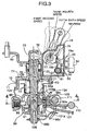
- a transmission case 11 of a manual transmission M for a vehicle having an even number of, e.g., six forward speed stages and one backward speed stage is comprised of a right case half 12 and a left case half 13 separated from each other at a split surface extending in a longitudinal direction of a vehicle body.
- An engine E is connected to one end of a main shaft SM through a shifting clutch CL.
- the main shaft SM is rotatably supported on the right and left case halves 12 and 13 with ball bearings 14 and 15 interposed therebetween.
- a counter shaft SC parallel to the main shaft SM is rotatably supported at its axially one end to the right case half 12 through a roller bearing 16, and at the axially other end to the left case half 13 through a ball bearing 17.
- the counter shaft SC is formed into a cylindrical shape, so that a lubricating oil can flow through the counter shaft SC.
- a guide member 19 is mounted at one end of the counter shaft SC for guiding the oil from an oil passage 18 defined in the right case half 12 into the counter shaft SC.
- An oil passage 20 is defined in the left case half 13 to communicate with the other end of the counter shaft SC, and a bolt 22 is threadedly engaged into the left case half 13 and has a collar 22a clamping an inner race of the ball bearing 17 between the collar 22a itself and a step 21 formed on an outer periphery of the other end of the counter shaft SC.
- the cylindrical bolt 22 for flowing of the lubricating oil therethrough is screwed into an inner periphery of the other end of the counter shaft SC in order to fix the inner race of the ball bearing 17, whereby a distance between the other end of the counter shaft SC and the left case half 13 can be set at a small value, and a reduction in size of the transmission case 11 can be achieved.
- an oil passage 23 is coaxially provided in the main shaft SM with one end closed and with the other end opening into the other end of the main shaft SM.
- a guide member 24 for guiding the oil from the oil passage 20 in the left case half 13 into the oil passage 23 is mounted at the other end of the main shaft SM.
- the shifting clutch CL includes a clutch wheel 25 fixedly connected to a crankshaft of the engine E, a pusher plate 26 disposed on one side of the clutch wheel 25, a clutch disk 28 which has facings 27, 27 on opposite surfaces thereof and which is interposed between the clutch wheel 25 and the pusher plate 26 and connected to the main shaft SM through a damper 29, and a diaphragm spring 30 for biasing the pusher plate 26 in a direction to clamp the facings 27, 27 between the clutch wheel 25 and the pusher plate 26.
- the crankshaft 25 and the main shaft SM are connected to each other by clamping the facings 27, 27 between the clutch wheel 25 and the pusher plate 26 by the repulsing force of the diaphragm spring 30.
- the crankshaft and the main shaft SM are disconnected from each other by operating a release bearing 32 leftwards as viewed in Fig.1 by a release fork 31.
- a main first-speed gear 34 and a main second-speed gear 35 are fixedly mounted on the main shaft SM, and a main third-speed gear 36, a main fourth-speed gear 37, a main fifth-speed gear 38 and a main sixth-speed gear 39 are relatively rotatably supported on the main shaft SM.
- a counter first-speed gear 40 and a counter second-speed gear 41 are relatively supported on the counter shaft SC and meshed with the main first-speed gear 34 and the main second-speed gear 35, respectively.
- a counter third-speed gear 42, a counter fourth-speed gear 43, a counter fifth-speed gear 44 and a counter sixth-speed gear 45 are fixedly mounted on the counter shaft SC and meshed with the main third-speed gear 36, the main fourth-speed gear 37, the main fifth-speed gear 38 and the main sixth-speed gear 39.
- a reverse idling shaft SR parallel to the main shaft SM and the counter shaft SC is fixedly supported at its opposite ends on the right and left case halves 12 and 13.
- a reverse idling gear 46 slidably supported on the reverse idling shaft SR can be meshed simultaneously with a main reverse gear 47 fixedly mounted on the main shaft SM and a counter reverse gear 48 relatively non-rotatably supported on the counter shaft SC.
- a first/second-speed synchronizing mechanism S1 mounted on the counter shaft SC includes a sleeve 49 which is movable in a range limited in an axial direction of the counter shaft SC and which is non-rotatable relative to the counter shaft SC.
- Any of the counter first-speed gear 40 and the counter second-speed gear 31 can be selected alternatively and coupled to the counter shaft SC by operating a first/second-speed shifting fork 50 retaining the sleeve 49 leftwards or rightwards as viewed in Fig.1. More specifically, when the sleeve 49 is moved rightwards as viewed in Fig.1, the counter first-speed gear 40 is coupled to the counter shaft SC, thereby establishing a first speed stage.
- the counter second-speed gear 41 is coupled to the counter shaft SC, thereby establishing a second shift stage.
- the counter reverse gear 48 is integrally formed on the sleeve 49.
- a third/fourth speed synchronizing mechanism S2 mounted on the main shaft SM includes a sleeve 51 which is movable in a range limited in an axial direction of the main shaft SM and which is non-rotatable relative to the main shaft SM, so that any of the main third-speed gear 36 and the main fourth-speed gear 37 can be selected alternatively and coupled to the main shaft SM by operating a third/fourth-speed shifting fork 52 retaining the sleeve 51 leftwards or rightwards as viewed in Fig.1. More specifically, when the sleeve 51 is moved rightwards as viewed in Fig.1 the main third-speed gear 36 is coupled to the main shaft SM, thereby establishing a third shift stage. When the sleeve 51 is moved leftwards as viewed in Fig.1, the main fourth-speed gear 37 is coupled to the main shaft SM, thereby establishing a fourth speed stage.
- a fifth/sixth-speed synchronizing mechanism S3 mounted on the main shaft SM includes a sleeve 53 which is movable in a range limited in the axial direction of the main shaft SM and which is non-rotatable relative to the main shaft SM, so that any of the main fifth-speed gear 38 and the main sixth-speed gear 39 can be selected alternatively and coupled to the main shaft SM by operating a fifth/sixth-speed shifting fork 54 retaining the sleeve 53 leftwards or rightwards as viewed in Fig.1. More specifically, when the sleeve 53 is moved rightwards as viewed in Fig.1 the main fifth-speed gear 38 is coupled to the main shaft SM, thereby establishing a fifth speed stage. When the sleeve 53 is moved leftwards as viewed in Fig.1, the main sixth-shift gear 39 is coupled to the main shaft SM, thereby establishing a sixth speed stage.
- the reverse idling gear 46 is rotatably retained on a reverse shifting fork 55, so that it can be meshed with the main reverse gear 47 and the counter reverse gear 48 by sliding the reverse idling gear 46 from a position shown by a solid line in Fig.1 to a position shown by a dashed line in Fig.1 by the reverse shifting form 55, thereby establishing a reverse speed stage.
- a change lever L of a changing system for selectively establishing one of the first to sixth speed stages and the reverse speed stage is operated in an operating pattern shown in Fig.2, so that the change lever L can be moved to any of a first/second-speed selecting position P1, a third/fourth-speed selecting position P2, a fifth/sixth-speed selecting position P3 and a reverse selecting position P4 by operating the change lever L in a selecting direction shown by SE.
- any of a first-speed position D1 and a second-speed position D2 can be selected by operating the change lever L in a shifting direction SH perpendicular to the selecting direction SE in the first/second-speed selecting position P1.
- Any of a third-speed position D3 and a fourth-speed position D4 can be selected by operating the change lever L in the shifting direction SH in the third/fourth-speed selecting position P2.
- Any of a fifth-speed position D5 and a sixth-speed position D6 can be selected by operating the change lever L in the shifting direction SH in the fifth/sixth-speed selecting position P3.
- a reverse position R can be selected by operating the change lever L in the shifting direction SH in the reverse selecting position P4.
- a cover member 71 is coupled to an upper portion of the left case half 13 in the transmission case 11 to cover an opening 70 provided in the left case half 13, and a guide bore 72 is provided in a central portion of the cover member 71.
- An upper portion of a shift-selecting shaft 73 is fitted into the guide bore 72 to protrude upwards from a cover plate 71, so that the shift-selecting shaft 73 can be turned about its axis and slid in an axial direction.
- a seal member 74 is interposed between the cover member 71 and the shift-selecting shaft 73.
- An engagement bore 75 is provided in the shift-selecting shaft 73 at a portion protruding upwards from the cover member 71, and a selecting lever 76 is engaged in the engagement bore 75.
- the selecting lever 76 is secured to a turning shaft 77 extending in a direction perpendicular to the axis of the shift-selecting shaft 73.
- the turning shaft 77 is turnably supported on a casing 78 fixedly mounted on the cover member 71.
- the selecting lever 76 is turned in response to the operation of the change lever L in the selecting direction SE (see Fig.2).
- the selecting lever 76 is turned to any of the first/second-speed selecting position P1, the third/fourth-speed selecting position P2, the fifth/sixth-speed selecting position P3 and the reverse selecting position P4, as shown in Fig.3, by the movement of the change lever L to any of the first/second-speed selecting position P1, the third/fourth-speed selecting position P2, the fifth/sixth-speed selecting position P3 and the reverse selecting position P4.
- the shift-selecting shaft 73 is also moved linearly in a direction of its axis in response to the turning of the selecting lever 76.
- a first cam 79 is fixed to the turning shaft 77 within the casing 78, and a second cam 80 having an axis parallel to the turning shaft 77 is fixedly provided on a shaft 81 which is turnably supported in the casing 78 and is meshed with the first cam 79.
- a first flat abutment face 79a and a second abutment face 79b leading to the first abutment 79a at a right angle are formed on the first cam 79 to face the second cam 80.
- the first flat abutment face 79a is adapted to perpendicularly intersect a plane including the axis of the shaft 81, when the turned position of the selecting lever 76 turned in unison with the turning shaft 77 is the fifth/sixth-speed selecting position.
- the second cam 80 is formed, so that it can be brought into abutment against and in engagement with the first and second abutment faces 79a and 79b of the first cam 79, when the turned position of the selecting lever 76 is the fifth/sixth-speed selecting position.
- a solenoid 84 is mounted to the casing 78 and has an axis which is substantially parallel to the first abutment face 79a of the first cam 79, when the turned position of the selecting lever 76 is the fifth/sixth-speed selecting position.
- the solenoid 84 includes a rod 83 which is adapted to protrude into a protruding position in an energized state of the solenoid 84 and to retreat in a non-energized state of the solenoid 84.
- a tip end of the rod 83 is adapted to abut against the second cam 80.
- a torsion spring 82 is mounted between the casing 78 and the second cam 80, and exhibits a spring force in a direction to push the second cam 80 against the tip end of the rod 83.
- the solenoid 84 is brought into the energized state, when a vehicle speed exceeds, for example, 15 km/hr.
- the second cam 80 is turned against the spring force of the torsion spring 82 to a position in which the second cam 80 can be engaged with the first cam 79, by the rod 83 lying in the protruding position.
- the turned position of the selecting lever 76 is the fifth/sixth-speed selecting position
- the second cam 80 is engaged with the first and second abutment faces 79a and 79b of the first cam 79, thereby inhibiting the turning of the selecting lever 76 from the fifth/sixth-speed selecting position to the reverse position.
- the reverse position cannot be selected.
- the solenoid 84 is positioned so that its operating axis is substantially perpendicular to a direction of a force which is applied from the first cam 79 to the second cam 80 upon the turning of the selecting lever 76 from the fifth/sixth-speed selecting position to the reverse position. Therefore, the force by turning of the selecting lever 76 from the fifth/sixth-speed selecting position to the reverse position cannot be applied to the solenoid 84.
- the solenoid 84 may be formed to exhibit a relatively small electromagnetic force.
- the second cam 80 can be turned in a clockwise direction as viewed in Fig.3, while the first cam 79 is pushing the rod 83 of the solenoid 84, that is, the turning of the selecting lever 76 from the fifth/sixth-speed selecting position toward the third/fourth-speed selecting position is permitted.
- the rod 83 is retracted by bringing the solenoid 84 into the non-energized state, and the second cam 80 is also turned, following the displacement of the rod 83, to a position in which it is not engaged with the first cam 79 (a position shown in a dashed line in Fig.3). Therefore, when the turned position of the selecting lever 76 is the fifth/sixth-speed selecting position, the second cam 80 cannot be engaged with the first cam 79, that is, the turning of the selecting lever 76 from the fifth/sixth-speed selecting position to the reverse position is permitted.
- a shifting lever 85 is fixed to the shift-selecting shaft 73 below the selecting lever 76 and adapted to be turned together with the shift-selecting shaft 73 in response to the operation of the change lever L in the shifting direction SH.
- the change lever L is in the first/second-speed selecting position P1, the third/fourth-speed selecting position P2, the fifth/sixth-speed selecting position P3 or the reverse selection position P4, the shift-selecting shaft 73 is in the neutral position.
- the shift-selecting shaft 73 is turned in a counterclockwise direction as viewed in Fig.4 from the neutral position in response to the operation of the change lever L to the first-speed position D1, the third-speed position D3 or the fifth-speed position D5, and turned in a clockwise direction as viewed in Fig.4 from the neutral position in response to the operation of the change lever L to the second-speed position D2, the fourth-speed position D4, the sixth-speed position or the reverse position R.
- an interlock plate 86 is mounted to the shift-selecting shaft 73.
- the interlock plate 86 includes a pair of upper and lower side plate portions 86a and 86b disposed at locations spaced apart from each other in an axial direction of the shift-selecting shaft 73 to extend through the shift-selecting shaft 73.
- a slit 87 is defined between the locking claws 86c and 86d to extend along a plane perpendicular to the axis of the shift-selecting shaft 73.
- a guide groove 88 is provided in the interlock plate 86 to extend along the axis of the shift-selecting shaft 73, and a detent pin 89 is fixed to the left case half 13 of the transmission case 11 and fitted into the guide groove 88. Therefore, the movement of the interlock plate 86 in a direction along the axis of the shift-selecting shaft 73 is permitted, but the turning of the interlock plate 86 about the axis of the shift-selecting shaft 73 is inhibited
- a shifting arm 90 and an interlock arm 91 which is a first interlocking member are interposed between the side plate portions 86a and 86b of the interlock plate 86 in such a manner that a portion of each of the arms is covered with the interlock plate 86.
- the shift-selecting shaft 73 extends through the shifting arm 90 and the interlock arm 91.
- the shifting arm 90 is fixed to the shift-selecting shaft 73 by a bolt 92, and the interlock arm 91 is operatively connected to the shifting arm 90.
- a detent mechanism 99 comprising a bottomed cylindrical retaining tube 93 mounted to the interlock plate 86 and having an axis perpendicular to the axis of the shift-selecting shaft 73, a ball 94 retained in the retaining tube 93 for movement in a direction along an axis of the retaining tube 93, a spring 95 mounted under compression between the retaining tube 93 and the ball 94 to exhibit a spring force for biasing the ball 94 toward the shifting arm 90, and recesses 96, 97 and 98 provided at three points spaced at equal distances apart from each other in a circumferential direction of the shifting arm 90 , so that they can accommodate a portion of the ball 94.
- the shifting arm 90 and the shift-selecting shaft 73 can be stopped with moderation by the detent mechanism 99 at three positions: any of the first-speed position, the third-speed position and the fifth-speed position; the neutral portion; and any of the second-speed position, the fourth-speed position, the sixth-speed position and the reverse position.
- the shifting arm 90 has a drive portion 90a integrally provided thereon.
- the drive portion 90a is disposed in the slit 87 defined between the locking claws 86c and 86d of the interlock plate 86.
- a first/second-speed shifting piece 101, a third/fourth-speed shifting piece 102, a fifth/sixth-speed shifting piece 103 and a reverse shifting piece 104 are arranged in the direction along the axis of the shift-selecting shaft 73.
- Tip ends of the shifting pieces 101 to 104 are formed into a substantially U-shape so that notches 101a, 102a, 103a and 104a are defined therein, respectively. These tip ends are disposed to sandwich the locking claws 86c and 86d of the interlock plate 86 from opposite sides, so that the drive portion 90a of the shifting arm 90 can be alternatively engaged into any of the notches 101a to 104a.
- a retainer 124 is in abutment against an upper surface of the interlock plate 86, more specifically, an upper surface of the side plate 86a, and a spring 125 is interposed between the retainer 124 and the cover member 71.
- the shift-selecting shaft 73 is provided with an annular step 73a facing the interlock plate 86, and a spring 127 is interposed between a spring-receiving plate 126 received on the step 73a and the retainer 124.
- the selecting lever 76 is biased toward the third/fourth-speed position, and the change lever L is retained in the third/fourth-speed selecting position P2, by spring forces exhibited by the two springs 125 and 127 acting on the shift-selecting shaft 73.
- the interlock arm 91 is sandwiched between the shifting arm 90 and the side plate 86b of the interlock plate 86, and has a cylindrical portion 91a which is integrally provided thereon so that its tip end is sliding contact with the shifting arm 90, and through which the shift-selecting shaft 73 extends.
- First and second projections 105 and 106 are provided in the interlock arm 91 at locations spaced apart from each other in a circumferential direction of the shift-selecting shaft 73 outside the cylindrical portion 91a, and protrude toward the shifting arm 90.
- a projection 107 is provided in the shifting arm 90 at a location corresponding to between the projections 105 and 106 to protrude toward the interlock arm 91.
- a torsion spring 108 is mounted between the shifting arm 90 and the interlock arm 91 to surround the cylindrical portion 91a of the interlock arm 91, and exhibits a spring force for biasing the shifting arm 90 and the interlock arm 91 in a direction to bring the projection 107 of the shifting arm 90 into engagement with the projection 105 of the interlock arm 91.
- the interlock arm 91 is turned in operative association with the shifting arm 90 by the spring force of the torsion spring 108.
- the first/second-speed shifting piece 101 is fixed to a first/second-speed shifting rod (not shown) which is supported in the transmission case 11 for movement in a direction parallel to the axis of the counter shaft SC and which includes the first/second-speed shifting fork 50.
- the third/fourth-speed shifting piece 102 is fixed to a third/fourth-speed shifting rod 110 which is supported in the transmission case 11 for movement in a direction parallel to the axis of the main shaft SM and which includes the third/fourth-speed shifting fork 52.
- the fifth/sixth-speed shifting piece 103 is fixed to a fifth/sixth-speed shifting rod 111 which is supported on the transmission case 11 for movement in the direction parallel to the axis of the main shaft SM and which includes the fifth/sixth-speed shifting fork 54.
- the reverse shift piece 104 is fixed to a reverse shifting rod 112 supported in the transmission case 11 for movement in a direction parallel to the axis of the reverse idling shaft SR.
- the reverse shifting fork 55 is turnably carried on a support plate 113 fixed to the right case half 12 of the transmission case 11 through a shaft 114 parallel to the shift-selecting shaft 73.
- a drive arm 115 integrally formed on the reverse shifting piece 104 is engaged with the reverse shifting fork 55 in such a manner that it turns the reverse shifting fork 55 in response to the operation of the reverse shifting piece 104 together with the reverse shifting rod 112.
- the interlock arm 91 functions in the following manner: When the interlock arm 91 is turned for shifting in operative association with the turning of the shifting arm 90 caused with the operation for shifting to the reverse position, it drives a preselected forward speed stage shifting piece, e.g., the third/fourth-speed shifting piece 102 by a predetermined amount at a initial stage of such shifting turning, and returns the third/fourth-speed shifting piece 102 to its original position at a final stage of the shifting turning. In this manner, the reverse speed stage is established, while preventing the generation of a gear chattering, by temporarily braking the main shaft SM.
- a preselected forward speed stage shifting piece e.g., the third/fourth-speed shifting piece 102 by a predetermined amount at a initial stage of such shifting turning
- returns the third/fourth-speed shifting piece 102 to its original position at a final stage of the shifting turning.
- the reverse speed stage is established, while preventing the generation of a gear chattering, by temporarily braking the main shaft
- the interlock arm 91 is integrally provided with first and second drive arm portions 116 and 117 overhanging outwards at locations spaced apart from each other in the circumferential direction of the shift-selecting shaft 73.
- the third/fourth-speed shifting piece 102 is integrally provided with a first engagement arm portion 118 capable of being brought into engagement with the first drive arm portion 116, and a second engagement arm portion 119 capable of being brought into engagement with the second drive arm portion 117, and the notch 102a is sandwiched between the first and second engagement arm portions 118 and 119.
- the first drive arm portion 116 is formed so that it can be brought into engagement with the first engagement arm portion 118 from the side of the notch 102a with the selecting movements of the shifting arm 90 and the interlock arm 91 in response to the operation of the change lever L lying in the neutral position to the reverse selecting position P4.
- the second drive arm portion 117 is formed so that it can be brought into engagement with the second engagement arm portion 119 from the side of the notch 102a with the shifting of the shifting arm 90 and the interlock arm 91 in response to the operation of the change lever L to the reverse position R in the reverse selecting position P4.
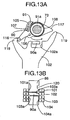
- the first engagement portion 118 is pushed at an initial stage of such shifting operation by the first drive arm portion 116 with the turning of the interlock arm 91, as shown in Fig.9A, whereby the third/fourth-speed shifting piece 102 is pushed by a predetermined amount toward the fourth-speed position, as shown in Fig.9B.
- the interlock plate 86 is provided with a recess 120 which accommodates a portion of the third/fourth-speed shifting piece 102 driven by the predetermined amount.
- the second engagement arm portion 119 is further pushed by the second drive arm portion 117, as shown in Fig.11A, and the third/fourth-speed shifting piece 102 is returned to the neutral position, as shown in Fig.11B.
- a restricting face 121 is formed at an end of the interlock plate 86 opposite from an operational direction 123 of the interlock plate 86 with the selecting operation of the change lever L toward the reverse position R, as shown in Fig.14.
- the restricting face 121 is formed in such a manner that among side faces of the interlock plate 86 facing the second-speed position, the fourth-speed position, the sixth-speed position and the reverse position, one side at the end opposite from the operational direction 123 protrudes by a protrusion amount d from the remaining side faces.
- the restricting face 121 is not opposed to any of the shifting pieces 101 to 104.
- the shifting arm 90 is driven for selection to a position where the drive portion 90a is opposed to the reverse shifting arm 104, as shown in Fig.14B, the restricting face 121 is opposed with a very small gap to one of side faces of the notch 101a in the first/second-speed shifting piece 101, which is on the side of the second-speed position.
- the shifting arm 90 and the interlock arm 91 operatively connected to the shifting arm 90 are interposed between the side plate portions 86a and 86b of the interlock plate 86, as described above, but in a manual transmission having an even number of, e.g., five forward stages, a shifting arm 90 and a reverse locking cam member 128 as a second interlock member having a shape different from that of the interlock arm 91 and operatively connected to the shifting arm 90 are interposed between the side plate portions 86a and 86b of the interlock plate 86, as shown in Fig.15.
- the reverse locking cam member 128 is adapted to prevent the mis-operation by inhibiting the turning of the shifting arm 90 from a fifth-speed position which is a forward highest-speed position to the reverse position.
- the reverse locking cam member 128 is operatively connected to the shifting arm 90 in an operative-connection structure similar to the operative-connection structure between the shifting arm 90 and the interlock arm 91 in the manual transmission having six forward six speed stages.
- the interlock 91 and the reverse locking cam member 128 having different shapes are prepared in advance, and any of a combination of the shifting arm 90 and the interlock arm 91 and a combination of the shifting arm 90 and the reverse locking cam member 128 can be alternatively selected whether the manual transmission is of the six forward speed stages or of the five forward speed stages.
- the shifting arm 90 and the interlock arm 91 operatively connected to the shifting arm 90 are interposed between the pair of side plate portions 86a and 86b of the interlock plate 86 mounted to the shift-selecting shaft 73.
- the shifting arm 90 and the reverse locking cam member 128 operatively connected to the shifting arm 90 are interposed between the side plate portions 86a and 86b.
- the interlock arm 91 used in the manual transmission having the six forward speed stages is operated to establish the reverse speed stage, and the reverse locking cam member 128 used in the manual transmission having the five forward speed stages functions to prevent the turning of the shifting arm 90 from the neutral position to the reverse position.
- Either the interlock arm 91 or the reverse locking cam member 128 is alternatively selected depending on whether the number of the forward speed stages is an even number or an odd number. Therefore, a satisfactory function can be exhibited in each of the changing systems in appropriate correspondence to the number of the forward speed stages.
- the interlock arm 91 functions to drive, by a predetermined amount, the third/fourth-speed shifting piece 102 at a preselected forward speed stage at an initial stage of the shifting operation to the reverse position, and to return the third/fourth-speed shifting piece 102 to the original position at a final stage of the shifting operation.
- the shifting arm 90 is driven for shifting toward the reverse position, the main shaft SM is braked, as when the third/fourth-speed shifting piece 102 establishes the third speed stage, and the braking of the main shaft SM is released at the final stage of the shifting operation.
- an exclusive mechanism for the reverse speed stage is not required, and the main shaft SM can be braked temporarily during establishment of the reverse speed stage to prevent the generation of a gear chattering. Additionally, it is possible to provide the compactness of the manual transmission in the direction along the axis of the main shaft SM and to provide a reduction in weight of the manual transmission by a value corresponding to that the exclusive mechanism is not required.
- the recess 120 is provided in the interlock plate 86 for accommodation of a portion of the third/fourth-speed shifting piece 102 driven by the predetermined amount at the initial stage of the shifting operation and hence, the braking of the main shaft SM can be achieved reliably by ensuring that the third/fourth-speed shifting piece 102 is driven reliably by the predetermined amount during the establishment of the reverse speed stage.
- the interlock plate 86 is formed into a shape such that when the shifting arm 90 having the drive portion 90a engaged with the reverse shifting piece 104 is turned for shifting to establish the reverse speed stage, the movement of the first/second-speed shifting piece 101 in the same direction as a direction of sliding movement of the reverse idling gear 46 is inhibited. Therefore, the movement of the first/second-speed shifting piece 101 in the same direction as a direction of sliding movement of the reverse idling gear 46 is inhibited by the interlock plate 68, when the shifting arm 90 is turned for shifting toward the reverse position in order to establish the reverse speed stage.
- the synchronizing effect of the first/second-speed synchronizing mechanism S1 ensures that such a phenomenon deteriorating the rotation of the main shaft SM cannot occur, and a thrust load provided upon the meshing of the reverse idling gear 46 with the main reverse gear 47 cannot be increased, so that the reverse shifting load can be reduced.
- a changing system in a manual transmission is provided.
- An interlock plate is mounted on a shift-selecting shaft capable of being moved axially in response to a selecting operation and turned about an axis in response to a shifting operation, so that the interlock plate cannot be turned about an axis of the shift-selecting shaft.
- the interlock plate has a pair of side plate portions which are provided at locations spaced apart from each other in an axial direction of the shift-selecting shaft and through which the shift-selecting shaft extends.
- a shifting arm disposed between the side plate portions is fixed to the shift-selecting shaft.
- the shifting arm and an interlock member operatively connected to the shifting arm are interposed between the side plate portions of the interlock plate.
- the shifting arm can be used commonly in manual transmissions, in despite of a difference in number of forward speed stages between the manual transmissions, thereby providing a reduction in cost and avoiding an increase in weight due to a variation in number of forward speed stages.
Landscapes
- Engineering & Computer Science (AREA)
- General Engineering & Computer Science (AREA)
- Mechanical Engineering (AREA)
- Gear-Shifting Mechanisms (AREA)
- Control Of Transmission Device (AREA)
- Structure Of Transmissions (AREA)
Claims (3)
- Wechselsystem in einem Handschaltgetriebe, in welchem eine Arretierplatte (86) an einer Schaltauswahlwelle (73) angebracht ist, welche in der Lage ist, in Reaktion auf einen Auswahlvorgang axial bewegt zu werden und in Reaktion auf einen Schaltvorgang um eine Achse gedreht zu werden, so dass die Arretierplatte (86) nicht um die Achse der Schaltauswahlwelle (73) gedreht werden kann, wobei die Arretierplatte (86) ein Paar von seitlichen Plattenabschnitten (86a, 86b) aufweist, die an in Richtung der Achse der Schaltauswahlwelle (73) im Abstand voneinander liegenden Stellen vorgesehen sind und durch die die Schaltauswahlwelle (73) verläuft, und wobei ein zwischen den seitlichen Plattenabschnitten (86a, 86b) angeordneter Schaltarm (90) an der Schaltauswahlwelle (73) befestigt ist,
wobei der Schaltarm (90) und ein von dem Schaltarm (90) separates, jedoch betriebsgemäß mit demselben verbundenes Arretierelement (91) zwischen den seitlichen Plattenabschnitten (86a, 86b) der Arretierplatte (86) angeordnet sind, und
wobei eine Mehrzahl von Schaltteilen (101-104) in einer Richtung entlang der Achse der Schaltauswahlwelle (73) parallel angeordnet sind und in der Lage sind, abhängig von dem Auswahlvorgang abwechselnd in Eingriff mit dem Schaltarm (90) gebracht zu werden,
dadurch gekennzeichnet, dass das Arretierelement (91) in Anlage gegen den Schaltarm (90) gebracht ist, wobei die Anlage derart ist, dass in einem anfänglichen Stadium eines Schaltvorgangs zu einer Rückwärtsstellung das Arretierelement (91) ein vorbestimmtes (102) der Schaltteile (102-104), welches einer Vorwärtsgangstufe entspricht, um einen vorbestimmten Betrag treibt und in einem letzten Stadium des Schaltvorgangs das Arretierelement (91) das vorgewählte (102) der Schaltteile (102-104), welches einer Vorwärtsgangstufe entspricht, zu einer ursprünglichen Stellung desselben zurückbringt. - Wechselsystem in einem Handschaltgetriebe nach Anspruch 1, wobei das Arretierelement (91) einen ersten Treiberarmabschnitt (116) aufweist, der in dem anfänglichen Stadium des Schaltvorgangs zu der Rückwärtsstellung das vorbestimmte (102) der Schaltteile (102-104) um den vorbestimmten Betrag schiebt, und einen zweiten Treiberarmabschnitt (117) aufweist, der das vorgewählte (102) der Schaltteile (102-104) zu der ursprünglichen Stellung zurückbringt, und wobei das vorbestimmte (102) der Schaltteile (102-104) einen ersten Eingriffsarmabschnitt (118) und einen zweiten Eingriffsarmabschnitt (119) aufweist, welche jeweils durch den ersten Treiberarmabschnitt (116) und den zweiten Treiberarmabschnitt (117) in Eingriff genommen werden.
- Wechselsystem in einem Handschaltgetriebe nach Anspruch 1, wobei die Arretierplatte (86), die in der Lage ist, in der axialen Richtung der Schaltauswahlwelle (73) bewegt zu werden, einen Abschnitt des Schaltarms (90) und einen Abschnitt des Arretierelements (91) abdeckt und wobei die Arretierplatte (86) mit einer Ausnehmung/Vertiefung (120) versehen ist, die dazu ausgebildet ist, einen Abschnitt des vorgewählten (102) der Schaltteile (102-104) aufzunehmen, welches in dem anfänglichen Stadium des Schaltvorgangs um den vorbestimmten Betrag getrieben wird.
Applications Claiming Priority (4)
| Application Number | Priority Date | Filing Date | Title |
|---|---|---|---|
| JP2001198482 | 2001-06-29 | ||
| JP2001198481A JP4065111B2 (ja) | 2001-06-29 | 2001-06-29 | 手動変速機のチェンジ装置 |
| JP2001198482A JP3980846B2 (ja) | 2001-06-29 | 2001-06-29 | 手動変速機のチェンジ装置 |
| JP2001198481 | 2001-06-29 |
Publications (3)
| Publication Number | Publication Date |
|---|---|
| EP1271013A2 EP1271013A2 (de) | 2003-01-02 |
| EP1271013A3 EP1271013A3 (de) | 2005-09-14 |
| EP1271013B1 true EP1271013B1 (de) | 2007-03-07 |
Family
ID=26617863
Family Applications (1)
| Application Number | Title | Priority Date | Filing Date |
|---|---|---|---|
| EP02014191A Expired - Fee Related EP1271013B1 (de) | 2001-06-29 | 2002-06-25 | Gangwähleinrichtung für ein Handschaltgetriebe |
Country Status (5)
| Country | Link |
|---|---|
| US (1) | US6892600B2 (de) |
| EP (1) | EP1271013B1 (de) |
| CN (1) | CN1210511C (de) |
| DE (1) | DE60218572T2 (de) |
| TW (1) | TW536597B (de) |
Families Citing this family (15)
| Publication number | Priority date | Publication date | Assignee | Title |
|---|---|---|---|---|
| FR2911172B1 (fr) * | 2007-01-10 | 2009-04-03 | Teleflex Automotive France Soc | Dispositif de commande de boite de vitesses |
| DE102007024030B4 (de) * | 2007-05-22 | 2011-01-05 | Zf Friedrichshafen Ag | Betätigungseinrichtung mit Sperrvorrichtung |
| ATE524676T1 (de) * | 2007-07-18 | 2011-09-15 | Schaeffler Technologies Gmbh | Schaltvorrichtung für ein schaltgetriebe eines kraftfahrzeugs mit verriegelungseinrichtung |
| US8327729B2 (en) * | 2009-02-27 | 2012-12-11 | Honda Motor Co., Ltd. | Shift drive mechanism for multi-speed transmission |
| DE102009027533A1 (de) * | 2009-07-08 | 2011-01-20 | Zf Friedrichshafen Ag | Schaltvorrichtung eines Kraftfahrzeug-Schaltgetriebes |
| DE102010006644A1 (de) * | 2010-02-03 | 2011-08-04 | GM Global Technology Operations LLC, ( n. d. Ges. d. Staates Delaware ), Mich. | Antriebseinheit eines Getriebes |
| DE102010017359A1 (de) * | 2010-06-14 | 2011-12-15 | Koki Technik Transmission Systems Gmbh | Betätigungsvorrichtung für ein Schaltgetriebe |
| TWI466789B (zh) * | 2011-01-07 | 2015-01-01 | Kwang Yang Motor Co | Power system of hybrid electric vehicle |
| EP2738429A4 (de) * | 2011-07-27 | 2015-12-02 | Toyota Motor Co Ltd | Manuelles schaltgetriebe für ein fahrzeug |
| KR20130017724A (ko) | 2011-08-11 | 2013-02-20 | 현대자동차주식회사 | 변속기의 변속 조작장치 |
| US9476500B2 (en) * | 2013-09-30 | 2016-10-25 | Kongsberg Driveline Systems I, Inc | Manual gear shifter assembly |
| CN105276155B (zh) * | 2014-05-30 | 2018-09-28 | 广州汽车集团股份有限公司 | 一种换挡机构 |
| CN104343962A (zh) * | 2014-09-30 | 2015-02-11 | 清河县科超汽车配件有限公司 | 电动汽车自锁式换挡操纵器 |
| US20160108994A1 (en) * | 2014-10-20 | 2016-04-21 | GM Global Technology Operations LLC | Transmission with reverse gear brake |
| US9671018B1 (en) | 2015-12-15 | 2017-06-06 | Eskridge, Inc. | Gear shift mechanism |
Family Cites Families (7)
| Publication number | Priority date | Publication date | Assignee | Title |
|---|---|---|---|---|
| DE3000577C2 (de) * | 1980-01-09 | 1983-01-27 | Zahnradfabrik Friedrichshafen Ag, 7990 Friedrichshafen | Schalteinrichtung für ein aus einem Haupt- und einem Zweibereichs-Gruppengetriebe bestehenden Zahnräder-Wechselgetriebe |
| JPS57198150A (en) * | 1981-05-30 | 1982-12-04 | Fuji Heavy Ind Ltd | Parking lock mechanism of change lever |
| JPS5975964U (ja) * | 1982-11-15 | 1984-05-23 | トヨタ自動車株式会社 | 手動変速機におけるリバ−スギヤ鳴り防止装置 |
| DE4320224B4 (de) * | 1992-06-24 | 2005-04-28 | Volkswagen Ag | Stufenwechselgetriebe |
| US5385223A (en) * | 1994-02-16 | 1995-01-31 | Saturn Corporation | Shift control mechanism for a multi-speed countershaft transmission |
| JPH0932921A (ja) * | 1995-07-17 | 1997-02-07 | Fuji Heavy Ind Ltd | 変速操作機構 |
| JP3706778B2 (ja) | 1999-10-18 | 2005-10-19 | 本田技研工業株式会社 | トランスミッションの変速装置 |
-
2002
- 2002-06-24 TW TW091113804A patent/TW536597B/zh not_active IP Right Cessation
- 2002-06-25 US US10/178,892 patent/US6892600B2/en not_active Expired - Lifetime
- 2002-06-25 EP EP02014191A patent/EP1271013B1/de not_active Expired - Fee Related
- 2002-06-25 DE DE60218572T patent/DE60218572T2/de not_active Expired - Lifetime
- 2002-06-28 CN CNB021251029A patent/CN1210511C/zh not_active Expired - Lifetime
Also Published As
| Publication number | Publication date |
|---|---|
| DE60218572D1 (de) | 2007-04-19 |
| US20030029264A1 (en) | 2003-02-13 |
| EP1271013A3 (de) | 2005-09-14 |
| TW536597B (en) | 2003-06-11 |
| CN1395053A (zh) | 2003-02-05 |
| EP1271013A2 (de) | 2003-01-02 |
| US6892600B2 (en) | 2005-05-17 |
| DE60218572T2 (de) | 2007-11-29 |
| CN1210511C (zh) | 2005-07-13 |
Similar Documents
| Publication | Publication Date | Title |
|---|---|---|
| EP1271013B1 (de) | Gangwähleinrichtung für ein Handschaltgetriebe | |
| EP1271014B1 (de) | Schaltsystem für manuelles Getriebe | |
| EP0148387B1 (de) | Schaltvorrichtung für handbetätigte Getriebe | |
| US4920815A (en) | Single shaft shifting mechanism | |
| KR101682262B1 (ko) | 자동차 수동 변속기의 변속 장치 | |
| EP2053282B1 (de) | Handschaltgetriebe mit Ganggeräuschverhinderungssystem | |
| JP2008504492A (ja) | ギアボックスの多くのギアの係合を防止するためのギアシフト要素固定装置を備えたギアボックス配置構成 | |
| US4584895A (en) | Transmission shift control | |
| US8056433B2 (en) | Shifting device for a manual transmission of a vehicle | |
| EP0694716B1 (de) | Schaltmechanismus für ein Mehrganggetriebe der Vorgelegebauart | |
| EP1094255B1 (de) | Getriebeschalteinrichtung | |
| JP3715209B2 (ja) | トランスミッション | |
| JP4065111B2 (ja) | 手動変速機のチェンジ装置 | |
| JP3980846B2 (ja) | 手動変速機のチェンジ装置 | |
| KR20030050732A (ko) | 수동변속기의 변속조작기구 | |
| EP2107279B1 (de) | Handschaltgetriebe mit Schaltgeräuschverhinderungsvorrichtung | |
| US5203225A (en) | Vehicle transmission gearshift for preventing accidental engagement | |
| JP2696630B2 (ja) | 手動変速機のギヤ鳴り防止機構 | |
| EP2133602B1 (de) | Getriebe | |
| JP2005155800A (ja) | リバースシフトのギヤ鳴き防止機構 | |
| GB2165324A (en) | Select/shift mechanism for change speed gearing | |
| JP2005090621A (ja) | 手動変速機のリバースミスシフト防止装置 | |
| EP1916446B1 (de) | Getriebe mit Synchronisierungskupplung | |
| JP2003113938A (ja) | 手動変速機におけるリバース誤操作防止構造 | |
| JP3668689B2 (ja) | トランスミッション |
Legal Events
| Date | Code | Title | Description |
|---|---|---|---|
| PUAI | Public reference made under article 153(3) epc to a published international application that has entered the european phase |
Free format text: ORIGINAL CODE: 0009012 |
|
| AK | Designated contracting states |
Kind code of ref document: A2 Designated state(s): AT BE CH CY DE DK ES FI FR GB GR IE IT LI LU MC NL PT SE TR |
|
| AX | Request for extension of the european patent |
Free format text: AL;LT;LV;MK;RO;SI |
|
| PUAL | Search report despatched |
Free format text: ORIGINAL CODE: 0009013 |
|
| AK | Designated contracting states |
Kind code of ref document: A3 Designated state(s): AT BE CH CY DE DK ES FI FR GB GR IE IT LI LU MC NL PT SE TR |
|
| AX | Request for extension of the european patent |
Extension state: AL LT LV MK RO SI |
|
| RIC1 | Information provided on ipc code assigned before grant |
Ipc: 7F 16H 63/30 A Ipc: 7F 16H 3/38 B |
|
| 17P | Request for examination filed |
Effective date: 20050906 |
|
| AKX | Designation fees paid |
Designated state(s): DE GB |
|
| GRAP | Despatch of communication of intention to grant a patent |
Free format text: ORIGINAL CODE: EPIDOSNIGR1 |
|
| GRAS | Grant fee paid |
Free format text: ORIGINAL CODE: EPIDOSNIGR3 |
|
| GRAA | (expected) grant |
Free format text: ORIGINAL CODE: 0009210 |
|
| AK | Designated contracting states |
Kind code of ref document: B1 Designated state(s): DE GB |
|
| REG | Reference to a national code |
Ref country code: GB Ref legal event code: FG4D |
|
| REF | Corresponds to: |
Ref document number: 60218572 Country of ref document: DE Date of ref document: 20070419 Kind code of ref document: P |
|
| PLBE | No opposition filed within time limit |
Free format text: ORIGINAL CODE: 0009261 |
|
| STAA | Information on the status of an ep patent application or granted ep patent |
Free format text: STATUS: NO OPPOSITION FILED WITHIN TIME LIMIT |
|
| 26N | No opposition filed |
Effective date: 20071210 |
|
| REG | Reference to a national code |
Ref country code: GB Ref legal event code: 746 Effective date: 20130204 |
|
| REG | Reference to a national code |
Ref country code: DE Ref legal event code: R084 Ref document number: 60218572 Country of ref document: DE Effective date: 20130211 |
|
| PGFP | Annual fee paid to national office [announced via postgrant information from national office to epo] |
Ref country code: GB Payment date: 20130619 Year of fee payment: 12 |
|
| GBPC | Gb: european patent ceased through non-payment of renewal fee |
Effective date: 20140625 |
|
| PG25 | Lapsed in a contracting state [announced via postgrant information from national office to epo] |
Ref country code: GB Free format text: LAPSE BECAUSE OF NON-PAYMENT OF DUE FEES Effective date: 20140625 |
|
| PGFP | Annual fee paid to national office [announced via postgrant information from national office to epo] |
Ref country code: DE Payment date: 20180612 Year of fee payment: 17 |
|
| REG | Reference to a national code |
Ref country code: DE Ref legal event code: R119 Ref document number: 60218572 Country of ref document: DE |
|
| PG25 | Lapsed in a contracting state [announced via postgrant information from national office to epo] |
Ref country code: DE Free format text: LAPSE BECAUSE OF NON-PAYMENT OF DUE FEES Effective date: 20200101 |