EP1271008A2 - Elektro-hydraulisches Steuerungssystem zum Steuern von Gangwechseln bei teil-oder vollautomatischen Getrieben von Fahrzeugen - Google Patents
Elektro-hydraulisches Steuerungssystem zum Steuern von Gangwechseln bei teil-oder vollautomatischen Getrieben von Fahrzeugen Download PDFInfo
- Publication number
- EP1271008A2 EP1271008A2 EP02013055A EP02013055A EP1271008A2 EP 1271008 A2 EP1271008 A2 EP 1271008A2 EP 02013055 A EP02013055 A EP 02013055A EP 02013055 A EP02013055 A EP 02013055A EP 1271008 A2 EP1271008 A2 EP 1271008A2
- Authority
- EP
- European Patent Office
- Prior art keywords
- electro
- control system
- hydraulic control
- hydraulic
- valve
- Prior art date
- Legal status (The legal status is an assumption and is not a legal conclusion. Google has not performed a legal analysis and makes no representation as to the accuracy of the status listed.)
- Granted
Links
Images
Classifications
-
- F—MECHANICAL ENGINEERING; LIGHTING; HEATING; WEAPONS; BLASTING
- F16—ENGINEERING ELEMENTS AND UNITS; GENERAL MEASURES FOR PRODUCING AND MAINTAINING EFFECTIVE FUNCTIONING OF MACHINES OR INSTALLATIONS; THERMAL INSULATION IN GENERAL
- F16H—GEARING
- F16H61/00—Control functions within control units of change-speed- or reversing-gearings for conveying rotary motion ; Control of exclusively fluid gearing, friction gearing, gearings with endless flexible members or other particular types of gearing
- F16H61/12—Detecting malfunction or potential malfunction, e.g. fail safe; Circumventing or fixing failures
-
- F—MECHANICAL ENGINEERING; LIGHTING; HEATING; WEAPONS; BLASTING
- F16—ENGINEERING ELEMENTS AND UNITS; GENERAL MEASURES FOR PRODUCING AND MAINTAINING EFFECTIVE FUNCTIONING OF MACHINES OR INSTALLATIONS; THERMAL INSULATION IN GENERAL
- F16H—GEARING
- F16H61/00—Control functions within control units of change-speed- or reversing-gearings for conveying rotary motion ; Control of exclusively fluid gearing, friction gearing, gearings with endless flexible members or other particular types of gearing
- F16H61/02—Control functions within control units of change-speed- or reversing-gearings for conveying rotary motion ; Control of exclusively fluid gearing, friction gearing, gearings with endless flexible members or other particular types of gearing characterised by the signals used
- F16H61/0202—Control functions within control units of change-speed- or reversing-gearings for conveying rotary motion ; Control of exclusively fluid gearing, friction gearing, gearings with endless flexible members or other particular types of gearing characterised by the signals used the signals being electric
- F16H61/0204—Control functions within control units of change-speed- or reversing-gearings for conveying rotary motion ; Control of exclusively fluid gearing, friction gearing, gearings with endless flexible members or other particular types of gearing characterised by the signals used the signals being electric for gearshift control, e.g. control functions for performing shifting or generation of shift signal
- F16H61/0206—Layout of electro-hydraulic control circuits, e.g. arrangement of valves
- F16H2061/0209—Layout of electro-hydraulic control circuits, e.g. arrangement of valves with independent solenoid valves modulating the pressure individually for each clutch or brake
-
- F—MECHANICAL ENGINEERING; LIGHTING; HEATING; WEAPONS; BLASTING
- F16—ENGINEERING ELEMENTS AND UNITS; GENERAL MEASURES FOR PRODUCING AND MAINTAINING EFFECTIVE FUNCTIONING OF MACHINES OR INSTALLATIONS; THERMAL INSULATION IN GENERAL
- F16H—GEARING
- F16H61/00—Control functions within control units of change-speed- or reversing-gearings for conveying rotary motion ; Control of exclusively fluid gearing, friction gearing, gearings with endless flexible members or other particular types of gearing
- F16H61/12—Detecting malfunction or potential malfunction, e.g. fail safe; Circumventing or fixing failures
- F16H2061/122—Avoiding failures by using redundant parts
-
- F—MECHANICAL ENGINEERING; LIGHTING; HEATING; WEAPONS; BLASTING
- F16—ENGINEERING ELEMENTS AND UNITS; GENERAL MEASURES FOR PRODUCING AND MAINTAINING EFFECTIVE FUNCTIONING OF MACHINES OR INSTALLATIONS; THERMAL INSULATION IN GENERAL
- F16H—GEARING
- F16H61/00—Control functions within control units of change-speed- or reversing-gearings for conveying rotary motion ; Control of exclusively fluid gearing, friction gearing, gearings with endless flexible members or other particular types of gearing
- F16H61/12—Detecting malfunction or potential malfunction, e.g. fail safe; Circumventing or fixing failures
- F16H2061/1256—Detecting malfunction or potential malfunction, e.g. fail safe; Circumventing or fixing failures characterised by the parts or units where malfunctioning was assumed or detected
- F16H2061/126—Detecting malfunction or potential malfunction, e.g. fail safe; Circumventing or fixing failures characterised by the parts or units where malfunctioning was assumed or detected the failing part is the controller
- F16H2061/1268—Electric parts of the controller, e.g. a defect solenoid, wiring or microprocessor
-
- F—MECHANICAL ENGINEERING; LIGHTING; HEATING; WEAPONS; BLASTING
- F16—ENGINEERING ELEMENTS AND UNITS; GENERAL MEASURES FOR PRODUCING AND MAINTAINING EFFECTIVE FUNCTIONING OF MACHINES OR INSTALLATIONS; THERMAL INSULATION IN GENERAL
- F16H—GEARING
- F16H61/00—Control functions within control units of change-speed- or reversing-gearings for conveying rotary motion ; Control of exclusively fluid gearing, friction gearing, gearings with endless flexible members or other particular types of gearing
- F16H61/12—Detecting malfunction or potential malfunction, e.g. fail safe; Circumventing or fixing failures
- F16H2061/1256—Detecting malfunction or potential malfunction, e.g. fail safe; Circumventing or fixing failures characterised by the parts or units where malfunctioning was assumed or detected
- F16H2061/1292—Detecting malfunction or potential malfunction, e.g. fail safe; Circumventing or fixing failures characterised by the parts or units where malfunctioning was assumed or detected the failing part is the power supply, e.g. the electric power supply
-
- F—MECHANICAL ENGINEERING; LIGHTING; HEATING; WEAPONS; BLASTING
- F16—ENGINEERING ELEMENTS AND UNITS; GENERAL MEASURES FOR PRODUCING AND MAINTAINING EFFECTIVE FUNCTIONING OF MACHINES OR INSTALLATIONS; THERMAL INSULATION IN GENERAL
- F16H—GEARING
- F16H61/00—Control functions within control units of change-speed- or reversing-gearings for conveying rotary motion ; Control of exclusively fluid gearing, friction gearing, gearings with endless flexible members or other particular types of gearing
- F16H61/02—Control functions within control units of change-speed- or reversing-gearings for conveying rotary motion ; Control of exclusively fluid gearing, friction gearing, gearings with endless flexible members or other particular types of gearing characterised by the signals used
- F16H61/0202—Control functions within control units of change-speed- or reversing-gearings for conveying rotary motion ; Control of exclusively fluid gearing, friction gearing, gearings with endless flexible members or other particular types of gearing characterised by the signals used the signals being electric
- F16H61/0204—Control functions within control units of change-speed- or reversing-gearings for conveying rotary motion ; Control of exclusively fluid gearing, friction gearing, gearings with endless flexible members or other particular types of gearing characterised by the signals used the signals being electric for gearshift control, e.g. control functions for performing shifting or generation of shift signal
- F16H61/0206—Layout of electro-hydraulic control circuits, e.g. arrangement of valves
-
- F—MECHANICAL ENGINEERING; LIGHTING; HEATING; WEAPONS; BLASTING
- F16—ENGINEERING ELEMENTS AND UNITS; GENERAL MEASURES FOR PRODUCING AND MAINTAINING EFFECTIVE FUNCTIONING OF MACHINES OR INSTALLATIONS; THERMAL INSULATION IN GENERAL
- F16H—GEARING
- F16H61/00—Control functions within control units of change-speed- or reversing-gearings for conveying rotary motion ; Control of exclusively fluid gearing, friction gearing, gearings with endless flexible members or other particular types of gearing
- F16H61/02—Control functions within control units of change-speed- or reversing-gearings for conveying rotary motion ; Control of exclusively fluid gearing, friction gearing, gearings with endless flexible members or other particular types of gearing characterised by the signals used
- F16H61/0262—Control functions within control units of change-speed- or reversing-gearings for conveying rotary motion ; Control of exclusively fluid gearing, friction gearing, gearings with endless flexible members or other particular types of gearing characterised by the signals used the signals being hydraulic
- F16H61/0276—Elements specially adapted for hydraulic control units, e.g. valves
-
- F—MECHANICAL ENGINEERING; LIGHTING; HEATING; WEAPONS; BLASTING
- F16—ENGINEERING ELEMENTS AND UNITS; GENERAL MEASURES FOR PRODUCING AND MAINTAINING EFFECTIVE FUNCTIONING OF MACHINES OR INSTALLATIONS; THERMAL INSULATION IN GENERAL
- F16H—GEARING
- F16H61/00—Control functions within control units of change-speed- or reversing-gearings for conveying rotary motion ; Control of exclusively fluid gearing, friction gearing, gearings with endless flexible members or other particular types of gearing
- F16H61/68—Control functions within control units of change-speed- or reversing-gearings for conveying rotary motion ; Control of exclusively fluid gearing, friction gearing, gearings with endless flexible members or other particular types of gearing specially adapted for stepped gearings
- F16H61/684—Control functions within control units of change-speed- or reversing-gearings for conveying rotary motion ; Control of exclusively fluid gearing, friction gearing, gearings with endless flexible members or other particular types of gearing specially adapted for stepped gearings without interruption of drive
- F16H61/686—Control functions within control units of change-speed- or reversing-gearings for conveying rotary motion ; Control of exclusively fluid gearing, friction gearing, gearings with endless flexible members or other particular types of gearing specially adapted for stepped gearings without interruption of drive with orbital gears
-
- Y—GENERAL TAGGING OF NEW TECHNOLOGICAL DEVELOPMENTS; GENERAL TAGGING OF CROSS-SECTIONAL TECHNOLOGIES SPANNING OVER SEVERAL SECTIONS OF THE IPC; TECHNICAL SUBJECTS COVERED BY FORMER USPC CROSS-REFERENCE ART COLLECTIONS [XRACs] AND DIGESTS
- Y10—TECHNICAL SUBJECTS COVERED BY FORMER USPC
- Y10S—TECHNICAL SUBJECTS COVERED BY FORMER USPC CROSS-REFERENCE ART COLLECTIONS [XRACs] AND DIGESTS
- Y10S477/00—Interrelated power delivery controls, including engine control
- Y10S477/906—Means detecting or ameliorating the effects of malfunction or potential malfunction
Definitions
- the invention relates to an electro-hydraulic control system for controlling of gear changes in semi or fully automatic transmissions according to the preamble of claim 1
- an electro-hydraulic To create a control system for fully or partially automated transmissions, which in case of failure of an electrical or electronic element in an emergency operation Switching operations enabled.
- a control system In a control system according to the invention all control magnets are switched off in case of power failure or other errors in the electronics.
- the control valve spool can then be hydraulically overridden with an emergency switching device in an advantageous manner. It is a passive redundancy, with an electrical "shift-by-wire" main path - ie in normal operation, gear changes are controlled by electrical signals - and a mechanical hydraulic side path, which only comes into action when the first one fails.
- the retention of the last-connected gear in case of electrical faults, up to hydraulic locking, as it corresponds to the state of the art in military tracked vehicles, can be realized with the selected approach.
- the emergency circuit makes it possible in a particularly advantageous manner, the transmission in case of failure of the supply voltage, a defect in the electronic control unit or another electrical fault to makeshift.
- the control system according to the invention is particularly flexible and can be easily adapted to different transmission types.
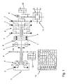
- Fig. 1 illustrates an exemplary transmission scheme of a six-speed transmission, in which an embodiment of the control system according to the invention is used.
- a control system according to the invention can also be provided for other types of semi-automatic or fully automatic transmissions.
- the output from the drive motor power is delivered via the transmission input 1 to a conventional torque converter 3.
- the torque converter is preferably equipped with a lock-up clutch 2.
- the impeller of the torque converter 3 can drive a power take-off gearbox.
- a speed sensor 4 is arranged, which receives the rotational speed of the drive motor.
- the impeller drives a hydraulic pump 12, which conveys the flow of oil to control and actuate the speed clutches.
- a retarder 5 is preferably arranged, which allows a wear-free braking of the vehicle. Furthermore, a further speed sensor 6 is arranged on the turbine shaft, which receives the input speed in the transmission.
- the switching elements 7 By appropriate actuation of the switching elements 7, the power flow can be determined by the planetary gear sets 8.
- the circuit diagram 13 can be seen which switching elements 7 are to be switched for which gear.
- the planetary gear sets 8 are used as switching elements multi-plate clutches, which are switched by hydraulically actuated piston.
- the rotatably mounted ring gears of the planetary gear sets 8 can be determined housing.
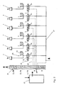
- FIG. 2 shows the elements of an electro-hydraulic control system according to the invention, as provided in the exemplary transmission according to FIG.
- Each switching element 7 is associated with a valve 22 to which the oil pressure of the hydraulic system 27 is present.
- the oil pressure of the hydraulic system 27 can be generated by one of the pumps 10 or 12 shown in FIG.
- electromagnetically controllable 3/2 way proportional valves are used, which are electrically controlled and regulated in normal operation by a control unit 20.
- the control unit 20 can realize load circuits, ie control gear changes, in which the power flow in the transmission is not interrupted.
- the control unit 20 sets the time of oil filling of the switching element to be switched 7 and controls in the range of synchronization, the torque transmission via the current gear down, while the ability to transmit torque through the next gear can be increased.
- the oil pressure in the two involved switching elements 7 must be controlled and regulated so that on the one hand no interruption of traction and on the other hand no overloading or destruction of the gear parts occurs.
- the preferred 3/2-way proportional valves have 3 oil connections and can be controlled by a controllable electromagnet.
- the oil flow rate is proportional to the electric current at the electromagnet.
- the electromagnet of the valve 22 is controlled by the control unit 20 by an electrical control terminal 23 so that it sets the oil pressure at the switching element 7 according to the control pulses via the delivery flow rate of the hydraulic system pressure 27.
- In the working line may preferably be provided near the cylinder of the switching element 7, a pressure sensor 24 which is connected via an electrical signal terminal 25 to the control unit 20.
- the signals of the speed sensors 4, 6, 9 shown in Figure 1 are also processed in the control unit 20 and can be used for a combined pressure / speed control.
- the valves 22 When de-energized, the valves 22 are brought by a spring in an exhibition.
- the - associated with the switching element 7 - working line is connected to the return line to the storage oil tank and the upcoming oil pressure of the hydraulic system 27 is locked.
- each individual switching element such as, for example, the circuit comfort and, in the event of failure of an electronic / electrical component, continue to switch through different gears via a mechanical / hydraulic emergency switch.
- the electromagnetic control of each valve 22 can also be hydraulically overridden.
- the electromagnet which is connected to the switching or regulating with the spool, the pressure chamber for the working oil and a pressure chamber for hydraulic oversteer integrated in a structural unit, wherein the slide separates the various pressure chambers against each other and according to the position its control edges, the corresponding paths releases or blocks.
- the pressure chamber for hydraulic override is connected to a hydraulic control line 26, which turns on the valve 22 when pressurized, that brings the working pressure of the hydraulic system 27 on the switching element 7 to the effect.
- a hydraulic control line 26 which turns on the valve 22 when pressurized, that brings the working pressure of the hydraulic system 27 on the switching element 7 to the effect.
- an emergency slide 21 is for each switchable in emergency mode and for the neutral position of the transmission a corresponding switching position and for each - a switching element 7 associated - valve 22 to provide a pressure connection.
- the pressure of the hydraulic system 27 is guided via appropriately provided channels to the valves 22 to be switched on and via corresponding other channels, the oil is passed from the Missionexcellent valves 22 in the storage tank.
- FIG. 2 shows only an exemplary embodiment of the emergency slide valve 21 according to the invention.
- the first position switches when the lock-up clutch of the torque converter 3 is closed, the 2nd gear to be able to tow the vehicle. In other positions, the 2nd, 4th or reverse gear can each operate on the torque converter 3.
- a fifth position puts the transmission in the neutral position.
- the emergency slide valve 21 is preferably integrated in a hydraulic control block on the gearbox and can be moved manually manually in the various switching positions. It can be provided mechanical transmission elements by which the emergency slide 21 is switched from the cab.
- the control unit 20 can be fed via other sensors with information about the electrical equipment, environmental influences or other signals and can, for example, when pressure deviations between harmless noise or error signals, which only occur for a short time and eg electromagnetically generated or caused by shocks and actual Falschrier, which could lead to the destruction of the transmission, different.
- the electrical devices Upon detection of actual errors such as short circuits or the operation of the emergency slide valve 21 despite active electro-hydraulic control, the electrical devices are de-energized and the valves 22 fall into the open state. In order for an abuse protection of the emergency slide valve 21 is ensured, which should perform the hydraulic override of the valves 22 only in de-energized state.
- other sensors such as micro-switches, directly on the emergency slide 21 and / or an associated actuator, eg in the cab, can be arranged. These transmit corresponding signals to the control unit 20, which can then initiate the appropriate measures.
- 3/2-way valves can be adjusted in an advantageous manner, the current for the zero crossing. That is, the electric current to be applied to lock the valve can be adjusted on the valve.
- other valves which function according to the same principle of operation can also be provided.
- the inventive electro-hydraulic control system is a flexible modular unit has been created which with increased comfort a high reliability - independent of changes in external parameters (e.g., temperature, etc.) as well as independent of changes in internal parameters (e.g., wear, coefficient of friction changes, etc.) - guaranteed and eliminated the influences of component tolerances for the control of different transmission types can be used and in case of failure of an electronic or electrical component in an emergency operation continues switching operations allows.
- external parameters e.g., temperature, etc.
- internal parameters e.g., wear, coefficient of friction changes, etc.
Abstract
Description
Die unsichere Größe beim automatischen Schaltvorgang ist die Totzeit zwischen einem Schaltkommando und der Wirkung am Schaltelement, welche abhängig ist vom Lüftspiel - d.h. vom Abstand der kraftübertragenden Elemente zueinander wenn sie in geöffnetem Zustand sind -, dem Verschleißzustand, den Einbautoleranzen usw. Diese Unsicherheit lässt sich durch Vorbefüllung der Gangkupplung sowie Messung des Arbeitsdrucks deutlich reduzieren und damit das Ansprechverhalten der Kupplung verbessern. Durch elektro-hydraulische Direktansteuerung jedes Schaltelements läßt sich das Schaltverhalten am wirkungsvollsten und flexibelsten beeinflussen, aber bei Ausfall einer elektrischen Einheit müssen zum Schutz der Fahrzeuginsassen und des Getriebes alle Schaltelemente deaktiviert oder die Schaltelemente eines bestimmten Ganges aktiviert werden, so daß keine Gangwechsel mehr möglich sind.
Die Notschaltung ermöglicht es in besonders vorteilhafter Weise das Getriebe bei Ausfall der Versorgungsspannung, einem Defekt im elektronischen Steuergerät oder einer anderen elektrischen Störung behelfsmäßig zu schalten.
Das erfindungsgemäße Steuerungssystem ist besonders flexibel und läßt sich in einfacher Weise an unterschiedliche Getriebetypen anpassen.
Weitere Merkmale und Vorteile ergeben sich aus den Unteransprüchen in Verbindung mit der Beschreibung.
- Fig. 1
- ein beispielhaftes Getriebeschema eines Sechs-Gang-Getriebes und die
- Fig. 2
- zeigt ein erfindungsgemäß ausgeführtes elektrohydraulisches Steuerungssystem zu diesem Getriebe.
Die vom Antriebsmotor abgegebene Leistung wird über den Getriebeeingang 1 an einen herkömmlichen Drehmomentwandler 3 abgegeben. Der Drehmomentwandler ist vorzugsweise mit einer Überbrückungskupplung 2 ausgestattet. Über einen Räderzug kann das Pumpenrad des Drehmomentwandlers 3 ein Nebenabtriebsgetriebe antreiben. An einem dieser Räder ist ein Drehzahlsensor 4 angeordnet, der die Drehzahl des Antriebsmotors aufnimmt. Über einen weiteren Räderzug treibt das Pumpenrad eine Hydraulikpumpe 12 an, welche den Ölstrom zur Steuerung und Betätigung der Gangkupplungen fördert.
Der Planetenradträger des letzten Planetenradsatzes treibt über Stirnräder in einen Getriebeabtrieb 11 - beispielsweise ein Differenzialgetriebe ein. An einem dieser Stirnräder ist ein weiterer Drehzahlsensor 9 angeordnet, der auch die Drehrichtung aufnimmt und somit Vor- oder Rückwärtsfahrt erkennt. Am Getriebeausgang wird über Stirnräder eine weitere Pumpe 10 angetrieben, welche bei stillstehendem Motor beim Anschleppen des Fahrzeuges für den nötigen Arbeits- und Steuerungsdruck im Hydrauliksystem sowie den Schmieröldruck sorgt.
Die Figur 2 zeigt die Elemente eines erfindungsgemäß ausgeführten elektro-hydraulischen Steuerungssystems, wie es beim beispielhaften Getriebe gemäß Figur 1 vorgesehen ist. Jedem Schaltelement 7 ist ein Ventil 22 zugeordnet, an dem der Öldruck des Hydrauliksystems 27 ansteht. Der Öldruck des Hydrauliksystems 27 kann durch eine der in Figur 1 gezeigten Pumpen 10 oder 12 erzeugt werden.
Vorzugsweise werden elektromagnetisch ansteuerbare 3/2 Wegeproportionalventile eingesetzt, die im Normalbetrieb durch eine Steuerungseinheit 20 elektrisch gesteuert und geregelt werden. Die Steuerungseinheit 20 kann Lastschaltungen realisieren, d. h. Gangwechsel steuern, bei welchen der Leistungsfluß im Getriebe nicht unterbrochen wird. Dazu legt die Steuerungseinheit 20 den Zeitpunkt der Ölbefüllung des zu schaltenden Schaltelementes 7 fest und regelt im Bereich der Synchronisierung die Drehmomentübertragung über den momentanen Gang herunter, während die Fähigkeit Drehmoment durch den nächsten Gang übertragen zu können gesteigert wird. Für solche Überschneidungsschaltungen muß der Öldruck in den beiden beteiligten Schaltelementen 7 so gesteuert und geregelt werden, daß einerseits keine Zugkraftunterbrechung und andererseits keine Überlastung bzw. Zerstörung der Getriebeteile eintritt. Die Überlastung bzw. Zerstörung kann durch im zeitlichen Ablauf zu große Öldrücke an den beteiligten Schaltelementen 7 verursacht werden.
Die bevorzugt eingesetzten 3/2-Wegeproportionalventile besitzen 3 Ölanschlüsse und sind durch einen ansteuerbaren Elektromagneten regelbar. Die Öldurchflußmenge verhält sich dabei proportional zum elektrischen Strom am Elektromagneten. Der Elektromagnet des Ventils 22 wird von der Steuerungseinheit 20 durch einen elektrischen Steueranschluß 23 so angesteuert, daß er über die Förderstrommenge des Hydrauliksystemdrucks 27 den Öldruck am Schaltelement 7 entsprechend der Steuerimpulse einstellt. In der Arbeitsleitung kann vorzugsweise nahe dem Zylinder des Schaltelements 7 ein Drucksensor 24 vorgesehen werden, der über einen elektrischen Signalanschluss 25 mit der Steuerungseinheit 20 verbunden ist.
Die Signale der in Figur 1 gezeigten Drehzahlsensoren 4, 6, 9 werden ebenfalls in der Steuerungseinheit 20 verarbeitet und können für eine kombinierte Druck/Drehzahlregelung verwendet werden.
Im stromlosen Zustand werden die Ventile 22 durch eine Feder in eine Ausstellung gebracht. Dabei ist die - mit dem Schaltelement 7 verbundene - Arbeitsleitung mit der Rückflußleitung zum Vorratsöltank verschaltet und der anstehende Öldruck des Hydrauliksystems 27 ist gesperrt.
An einem Notschaltschieber 21 ist für jeden im Notbetrieb schaltbaren Gang sowie für die Neutralstellung des Getriebes eine entsprechende Schaltstellung und für jedes - einem Schaltelement 7 zugeordnetem - Ventil 22 ein Druckanschluß vorzusehen. In der jeweiligen Schaltstellung des Notschaltschiebers 21 wird der Druck des Hydrauliksystems 27 über entsprechend vorgesehene Kanäle an die einzuschaltenden Ventile 22 geführt und über entsprechende andere Kanäle wird das Öl von den auszuschaltenden Ventilen 22 in den Vorratstank geleitet. In der Figur 2 ist lediglich eine beispielhafte Ausführung des erfindungsgemäßen Notschaltschiebers 21 dargestellt. Die erste Stellung schaltet bei geschlossener Überbrückungskupplung des Drehmomentwandlers 3 den 2. Gang, um das Fahrzeug Anschleppen zu können. In weiteren Stellungen läßt sich der 2., 4. Gang oder der Rückwärtsgang jeweils über den Drehmomentwandler 3 betreiben. Eine fünfte Stellung bringt das Getriebe in die Neutralstellung.
Der Notschaltschieber 21 ist vorzugsweise in einen hydraulischen Steuerungsblock am Getriebe integriert und läßt sich mechanisch manuell in die verschiedenen Schaltstellungen verschieben. Es können mechanische Übertragungselemente vorgesehen werden, durch die der Notschaltschieber 21 vom Fahrerhaus aus schaltbar ist.
Die Steuerungseinheit 20 kann über weitere Sensoren mit Informationen über die elektrischen Einrichtungen, Umgebungseinflüsse oder mit sonstigen Signalen gespeist werden und kann beispielsweise bei Auftreten von Druckabweichungen zwischen unbedenklichen Stör- oder Fehlersignalen, welche nur kurzzeitig auftreten und z.B. elektromagnetisch erzeugt oder durch Erschütterungen verursacht werden sowie tatsächlichen Falschdrücken, die zur Zerstörung des Getriebes führen könnten, unterscheiden. Bei Erkennen von tatsächlichen Fehlern wie beispielsweise Kurzschlüssen oder der Bedienung des Notschaltschiebers 21 trotz aktiver elektrohydraulischer Steuerung, werden die elektrischen Einrichtungen stromlos geschaltet und die Ventile 22 fallen in den geöffneten Zustand. Damit ist ein Mißbrauchsschutz des Notschaltschiebers 21 gewährleistet, der die hydraulische Übersteuerung der Ventile 22 nur in stromlosen Zustand durchführen soll.
Neben der Erkennung der Bedienung bzw. Fehlbedienung des Notschaltschiebers 21 durch die oben beschriebenen Fehldrücke, können auch weitere Sensoren, wie beispielsweise Mikroschalter, direkt am Notschaltschieber 21 und/oder einer zugehörigen Betätigungseinrichtung, z.B. im Fahrerhaus, angeordnet werden. Diese geben entsprechende Signale an die Steuerungseinheit 20 weiter, welche daraufhin die entsprechenden Maßnahmen einleiten kann.
Bei den vorzugsweise eingesetzten 3/2-Wegeventilen läßt sich in vorteilhafter Weise der Strom für den Nulldurchgang einstellen. Das heißt der elektrische Strom der anzulegen ist, um das Ventil zu sperren läßt sich am Ventil verstellen.
Als Alternative zu den beschriebenen Wege-Ventilen können auch andere nach gleichem Wirkungsprinzip funktionierende Ventile vorgesehen werden.
- 1
- Getriebeeingang
- 2
- Überbrückungskupplung
- 3
- Drehmomentwandler
- 4
- Drehzahlsensor
- 5
- Retarder
- 6
- Drehzahlsensor
- 7
- Schaltelement
- 8
- Planetensätze
- 9
- Drehzahlsensor
- 10
- Pumpe
- 11
- Getriebeabtrieb
- 12
- Pumpe
- 13
- Schaltschema
- 20
- Steuerungseinheit
- 21
- Notschaltschieber
- 22
- Ventil
- 23
- Steueranschluß
- 24
- Drucksensor
- 25
- Signalanschluß
- 26
- Hydrauliksteuerleitung
- 27
- Hydrauliksystem
Claims (10)
- Elektro-hydraulisches Steuerungssystem zum Steuern von Gangwechseln bei teil- oder vollautomatischen Getrieben von Fahrzeugen mit mindestens einem hydraulisch betätigbaren Schaltelement (7), einer Steuerungseinheit (20) mit Signaleingang für mindestens einen Sensor (4, 6, 9, 24) und Signalausgang zum elektrischen Ansteuern von mindestens einem Ventil (22) zum Betätigen eines Schaltelements (7), dadurch gekennzeichnet, dass die elektrische Ansteuerung der Ventile (22) abschaltbar und durch einen Notschaltschieber (21) hydraulisch steuerbar sind.
- Elektro-hydraulisches Steuerungssystem nach Anspruch 1, dadurch gekennzeichnet, dass die Schaltelemente (7) durch Hydraulikkolben schaltbare Reibungskupplungen oder Bremsen sind und das durch sie übertragbare Drehmoment oder Bremsmoment über den Öldruck einstellbar ist.
- Elektro-hydraulisches Steuerungssystem nach einem der vorhergehenden Ansprüche, dadurch gekennzeichnet, dass für alle Schaltelemente (7) einzeln elektrohydraulisch ansteuerbare Regelventile (22) vorgesehen sind, bei welchen die elektromagnetische Schalt/Regeleinheit, ein Druckraum zum hydraulischen Übersteuern sowie Druckräume für den Arbeitsöldruck jeweils in einem Gehäuse integriert sind.
- Elektro-hydraulisches Steuerungssystem nach einem der vorhergehenden Ansprüche, dadurch gekennzeichnet, dass der durch das Ventil (22) fließende Volumenstrom proportional zum elektrischen Strom ist und der elektrische Strom, welcher für die Sperrstellung des Ventils (22) anzulegen ist, einstellbar ist.
- Elektro-hydraulisches Steuerungssystem nach einem der vorhergehenden Ansprüche, dadurch gekennzeichnet, dass an jedem Schaltelement (7) ein Drucksensor (24) und am Getriebe mindestens ein Drehzahlsensor (4; 6; 9) vorgesehen ist, deren Signale in der Steuerungseinheit (20) auswertbar sind.
- Elektro-hydraulisches Steuerungssystem nach einem der vorhergehenden Ansprüche, dadurch gekennzeichnet, dass im Normalbetrieb jeder Gangwechsel alleine durch elektrische Signalübermittlung eingeleitet und von der Steuerungseinheit (20) durch eine kombinierte Druck-/Drehzahlregelung steuerbar ist.
- Elektro-hydraulisches Steuerungssystem nach einem der vorhergehenden Ansprüche, dadurch gekennzeichnet, dass der Notschaltschieber (21) mechanisch betätigbar ist und über mechanische Übertragungselemente von einem Fahrerhaus aus schaltbar ist.
- Elektro-hydraulisches Steuerungssystem nach einem der vorhergehenden Ansprüche, dadurch gekennzeichnet, dass bei Betätigung des Notschaltschiebers (21) alle elektrischen Steuerungseinrichtungen stromlos geschaltet werden.
- Elektro-hydraulisches Steuerungssystem nach einem der vorhergehenden Ansprüche, dadurch gekennzeichnet, dass am Notschaltschieber (21) und/oder an einer zugehörigen Betätigungseinrichtung Sensoren vorgesehen sind, welche die Betätigung des Notschaltschiebers (21) erkennen und die entsprechenden Signale an die Steuerungseinrichtung (20) weitergeben.
- Elektro-hydraulisches Steuerungssystem insbesondere nach einem der vorhergehenden Ansprüche, dadurch gekennzeichnet, dass das Ventil (22) sowohl elektrisch als auch hydraulisch ansteuerbar ist.
Applications Claiming Priority (2)
| Application Number | Priority Date | Filing Date | Title |
|---|---|---|---|
| DE10128805A DE10128805B4 (de) | 2001-06-18 | 2001-06-18 | Eelektro-hydraulisches Steuerungssystem zum Steuern von Gangwechseln bei teil- oder vollautomatischen Getrieben von Fahrzeugen |
| DE10128805 | 2001-06-18 |
Publications (3)
| Publication Number | Publication Date |
|---|---|
| EP1271008A2 true EP1271008A2 (de) | 2003-01-02 |
| EP1271008A3 EP1271008A3 (de) | 2004-08-25 |
| EP1271008B1 EP1271008B1 (de) | 2006-08-02 |
Family
ID=7688227
Family Applications (1)
| Application Number | Title | Priority Date | Filing Date |
|---|---|---|---|
| EP02013055A Expired - Fee Related EP1271008B1 (de) | 2001-06-18 | 2002-06-13 | Elektro-hydraulisches Steuerungssystem zum Steuern von Gangwechseln bei teil-oder vollautomatischen Getrieben von Fahrzeugen |
Country Status (4)
| Country | Link |
|---|---|
| US (1) | US6659899B2 (de) |
| EP (1) | EP1271008B1 (de) |
| CA (1) | CA2390890C (de) |
| DE (2) | DE10128805B4 (de) |
Families Citing this family (9)
| Publication number | Priority date | Publication date | Assignee | Title |
|---|---|---|---|---|
| JP4774680B2 (ja) | 2004-05-07 | 2011-09-14 | トヨタ自動車株式会社 | 車両用自動変速機の油圧制御装置 |
| DE102004054617B3 (de) * | 2004-11-11 | 2006-05-11 | Zf Friedrichshafen Ag | Betätigungseinrichtung mit Tasten |
| DE102005012586B4 (de) | 2005-03-18 | 2024-02-15 | Zf Friedrichshafen Ag | Elektrohydraulische Getriebesteuervorrichtung |
| DE102009001601A1 (de) * | 2009-03-17 | 2010-09-23 | Zf Friedrichshafen Ag | Vorrichtung für einen Fahrzeugantriebsstrang mit einer Getriebeeinrichtung zum Variieren verschiedener Übersetzungen |
| CN104776217B (zh) * | 2009-06-05 | 2017-04-12 | 艾里逊变速箱公司 | 电动液压控制系统校准和诊断 |
| US8221288B2 (en) | 2009-06-05 | 2012-07-17 | Allison Transmission, Inc. | Electro-hydraulic control system diagnostics |
| US8437932B2 (en) * | 2009-06-05 | 2013-05-07 | Allison Transmission, Inc. | Main modulation calibration using clutch trim valve |
| US8548698B2 (en) * | 2009-06-05 | 2013-10-01 | Allison Transmission, Inc. | Main modulation calibration using control main valve |
| US8504263B2 (en) * | 2010-04-23 | 2013-08-06 | GM Global Technology Operations LLC | Accumulator working volume management and adaptation |
Family Cites Families (13)
| Publication number | Priority date | Publication date | Assignee | Title |
|---|---|---|---|---|
| US4351206A (en) * | 1980-04-28 | 1982-09-28 | Ford Motor Company | Electronic and hydraulic control system for automatic gear change transmission |
| US4535681A (en) * | 1983-05-31 | 1985-08-20 | Kabushiki Kaisha Komatsu Seisakusho | Fluid operated transmission control system |
| US4981052A (en) * | 1986-08-08 | 1991-01-01 | Zahnradfabrik Friedrichshafen Ag | Transmission control fail safe system |
| JPS63243553A (ja) * | 1987-03-30 | 1988-10-11 | Hino Motors Ltd | トランスミツシヨンの非常コントロ−ル装置 |
| US4827806A (en) * | 1988-08-11 | 1989-05-09 | General Motors Corporation | Logic valving for a transmission control |
| US4841816A (en) * | 1988-08-11 | 1989-06-27 | General Motors Corporation | Hydraulic control for a power transmission with a manual range selector valve |
| WO1990014534A1 (de) * | 1989-05-16 | 1990-11-29 | Zahnradfabrik Friedrichshafen Ag | Elektro-pneumatisches schaltsystem |
| AU7207594A (en) * | 1993-07-06 | 1995-02-06 | Caterpillar Inc. | Electro-hydraulic transmission control |
| US5445578A (en) * | 1993-12-17 | 1995-08-29 | General Motors Corporation | Hydraulic control for a power transmission with a manual override |
| US5682792A (en) * | 1996-06-28 | 1997-11-04 | Caterpillar Inc. | Dependent latching system for a transmission |
| US6077182A (en) * | 1999-06-14 | 2000-06-20 | General Motors Corporation | Relay valve with latch area for controlling a friction device |
| US6520881B1 (en) * | 2001-08-06 | 2003-02-18 | General Motors Corporation | Fly-by-wire electro-hydraulic control mechanism for a six speed transmission |
| US6585617B1 (en) * | 2001-12-19 | 2003-07-01 | General Motors Corporation | Electro-hydraulic control system for a multi-speed power transmission |
-
2001
- 2001-06-18 DE DE10128805A patent/DE10128805B4/de not_active Expired - Fee Related
-
2002
- 2002-06-11 US US10/170,084 patent/US6659899B2/en not_active Expired - Lifetime
- 2002-06-13 EP EP02013055A patent/EP1271008B1/de not_active Expired - Fee Related
- 2002-06-13 DE DE50207689T patent/DE50207689D1/de not_active Expired - Lifetime
- 2002-06-18 CA CA002390890A patent/CA2390890C/en not_active Expired - Fee Related
Non-Patent Citations (1)
| Title |
|---|
| None |
Also Published As
| Publication number | Publication date |
|---|---|
| DE50207689D1 (de) | 2006-09-14 |
| CA2390890C (en) | 2005-12-06 |
| CA2390890A1 (en) | 2002-12-18 |
| EP1271008A3 (de) | 2004-08-25 |
| US6659899B2 (en) | 2003-12-09 |
| DE10128805B4 (de) | 2006-01-05 |
| DE10128805A1 (de) | 2003-01-02 |
| US20020193198A1 (en) | 2002-12-19 |
| EP1271008B1 (de) | 2006-08-02 |
Similar Documents
| Publication | Publication Date | Title |
|---|---|---|
| DE3532784C2 (de) | ||
| EP1910151B1 (de) | Elektrohydraulische lenkung | |
| EP1846807B1 (de) | Ventil, insbesondere proportional-druckbegrenzungsventil | |
| EP2754911B1 (de) | Hydraulische Betätigungsvorrichtung für die Betätigung wenigstens einer Reibkupplung und wenigstens eines Getriebestellglieds in einem Kraftfahrzeug | |
| EP1219870B1 (de) | Elektronisch-hydraulische Steuerung für Antriebssysteme von Fahrzeugen mit automatischem Gangwechsel | |
| EP1767825B1 (de) | Hydraulische Steuerungsvorrichtung für ein automatisiertes Doppelkupplungsgetriebe | |
| DE4320353A1 (de) | Hydraulische Getriebeansteuerung | |
| DE10134115A1 (de) | Hydraulikkreis und Verfahren zur hydraulischen Steuerung eines Doppelkupplungsgetriebes | |
| WO2004097265A1 (de) | Hydraulikkreis zur steuerung eines antriebsstranges | |
| DE10338355A1 (de) | Doppelkupplungsgetriebe mit Zustandshaltefunktion | |
| DE4124384C1 (de) | ||
| DE102010043257A1 (de) | Vorrichtung zum Betreiben einer Parksperreneinrichtung | |
| DE69937115T2 (de) | Verfahren zum steuern des hydraulikdrucks in schaltgetrieben mit hydraulischen kupplungen | |
| DE3801845C2 (de) | ||
| EP1271008B1 (de) | Elektro-hydraulisches Steuerungssystem zum Steuern von Gangwechseln bei teil-oder vollautomatischen Getrieben von Fahrzeugen | |
| DE112018003325T5 (de) | Steuerungssystem und Verfahren dafür für ein mehrgängiges Getriebe | |
| DE4432851C2 (de) | Anordnung zum Steuern einer selbsttätigen Schaltvorrichtung eines Gangwechselgetriebes eines Kraftfahrzeuges in eine Stellung für einen Notlauf | |
| DE4124385C1 (de) | ||
| DE10135862A1 (de) | Fahrzeuglenkung | |
| EP2090809B1 (de) | Steuerungsverfahren und Steuerungsvorrichtung eines Wendegetriebes | |
| DE102006063073B3 (de) | Schaltgetriebe, mindestens eine angetriebene Kolben-Zylinder-Einheit aufweisend, sowie ein Verfahren zum Betrieb des Schaltgetriebes | |
| WO1999008890A1 (de) | Steuerung einer klimaanlage in einem kraftfahrzeug | |
| DE102006063077B3 (de) | Schaltgetriebe, mindestens eine angetriebene Kolben-Zylinder-Einheit aufweisend, sowie ein Verfahren zum Betrieb des Schaltgetriebes | |
| DE102021213980A1 (de) | Hydrauliksystem eines Automatikgetriebes, insbesondere eines Automatikgetriebes einer elektrischen Fahrzeugachse, Automatikgetriebe mit einem Hydrauliksystem und elektrische Fahrzeugachse | |
| WO1995034774A1 (de) | Schaltventil |
Legal Events
| Date | Code | Title | Description |
|---|---|---|---|
| PUAI | Public reference made under article 153(3) epc to a published international application that has entered the european phase |
Free format text: ORIGINAL CODE: 0009012 |
|
| AK | Designated contracting states |
Kind code of ref document: A2 Designated state(s): AT BE CH CY DE DK ES FI FR GB GR IE IT LI LU MC NL PT SE TR |
|
| AX | Request for extension of the european patent |
Free format text: AL;LT;LV;MK;RO;SI |
|
| PUAL | Search report despatched |
Free format text: ORIGINAL CODE: 0009013 |
|
| AK | Designated contracting states |
Kind code of ref document: A3 Designated state(s): AT BE CH CY DE DK ES FI FR GB GR IE IT LI LU MC NL PT SE TR |
|
| AX | Request for extension of the european patent |
Extension state: AL LT LV MK RO SI |
|
| 17P | Request for examination filed |
Effective date: 20040916 |
|
| 17Q | First examination report despatched |
Effective date: 20041213 |
|
| AKX | Designation fees paid |
Designated state(s): DE FR GB IT |
|
| GRAP | Despatch of communication of intention to grant a patent |
Free format text: ORIGINAL CODE: EPIDOSNIGR1 |
|
| GRAS | Grant fee paid |
Free format text: ORIGINAL CODE: EPIDOSNIGR3 |
|
| GRAA | (expected) grant |
Free format text: ORIGINAL CODE: 0009210 |
|
| AK | Designated contracting states |
Kind code of ref document: B1 Designated state(s): DE FR GB IT |
|
| PG25 | Lapsed in a contracting state [announced via postgrant information from national office to epo] |
Ref country code: IT Free format text: LAPSE BECAUSE OF FAILURE TO SUBMIT A TRANSLATION OF THE DESCRIPTION OR TO PAY THE FEE WITHIN THE PRESCRIBED TIME-LIMIT;WARNING: LAPSES OF ITALIAN PATENTS WITH EFFECTIVE DATE BEFORE 2007 MAY HAVE OCCURRED AT ANY TIME BEFORE 2007. THE CORRECT EFFECTIVE DATE MAY BE DIFFERENT FROM THE ONE RECORDED. Effective date: 20060802 |
|
| REG | Reference to a national code |
Ref country code: GB Ref legal event code: FG4D Free format text: NOT ENGLISH |
|
| REF | Corresponds to: |
Ref document number: 50207689 Country of ref document: DE Date of ref document: 20060914 Kind code of ref document: P |
|
| ET | Fr: translation filed | ||
| GBT | Gb: translation of ep patent filed (gb section 77(6)(a)/1977) |
Effective date: 20061219 |
|
| PLBE | No opposition filed within time limit |
Free format text: ORIGINAL CODE: 0009261 |
|
| STAA | Information on the status of an ep patent application or granted ep patent |
Free format text: STATUS: NO OPPOSITION FILED WITHIN TIME LIMIT |
|
| 26N | No opposition filed |
Effective date: 20070503 |
|
| REG | Reference to a national code |
Ref country code: FR Ref legal event code: PLFP Year of fee payment: 15 |
|
| REG | Reference to a national code |
Ref country code: FR Ref legal event code: PLFP Year of fee payment: 16 |
|
| REG | Reference to a national code |
Ref country code: FR Ref legal event code: PLFP Year of fee payment: 17 |
|
| PGFP | Annual fee paid to national office [announced via postgrant information from national office to epo] |
Ref country code: IT Payment date: 20190624 Year of fee payment: 18 Ref country code: DE Payment date: 20190619 Year of fee payment: 18 |
|
| PGFP | Annual fee paid to national office [announced via postgrant information from national office to epo] |
Ref country code: FR Payment date: 20190619 Year of fee payment: 18 |
|
| PGFP | Annual fee paid to national office [announced via postgrant information from national office to epo] |
Ref country code: GB Payment date: 20190619 Year of fee payment: 18 |
|
| REG | Reference to a national code |
Ref country code: DE Ref legal event code: R119 Ref document number: 50207689 Country of ref document: DE |
|
| GBPC | Gb: european patent ceased through non-payment of renewal fee |
Effective date: 20200613 |
|
| PG25 | Lapsed in a contracting state [announced via postgrant information from national office to epo] |
Ref country code: FR Free format text: LAPSE BECAUSE OF NON-PAYMENT OF DUE FEES Effective date: 20200630 Ref country code: GB Free format text: LAPSE BECAUSE OF NON-PAYMENT OF DUE FEES Effective date: 20200613 |
|
| PG25 | Lapsed in a contracting state [announced via postgrant information from national office to epo] |
Ref country code: DE Free format text: LAPSE BECAUSE OF NON-PAYMENT OF DUE FEES Effective date: 20210101 |
|
| PG25 | Lapsed in a contracting state [announced via postgrant information from national office to epo] |
Ref country code: IT Free format text: LAPSE BECAUSE OF NON-PAYMENT OF DUE FEES Effective date: 20200613 |