EP1271005A2 - Procédé et dispositif de reconnaissance de rapport de boite de vitesses - Google Patents
Procédé et dispositif de reconnaissance de rapport de boite de vitesses Download PDFInfo
- Publication number
- EP1271005A2 EP1271005A2 EP02011656A EP02011656A EP1271005A2 EP 1271005 A2 EP1271005 A2 EP 1271005A2 EP 02011656 A EP02011656 A EP 02011656A EP 02011656 A EP02011656 A EP 02011656A EP 1271005 A2 EP1271005 A2 EP 1271005A2
- Authority
- EP
- European Patent Office
- Prior art keywords
- limit values
- gearbox
- ratio
- speed
- engaged
- Prior art date
- Legal status (The legal status is an assumption and is not a legal conclusion. Google has not performed a legal analysis and makes no representation as to the accuracy of the status listed.)
- Granted
Links
Images


Classifications
-
- F—MECHANICAL ENGINEERING; LIGHTING; HEATING; WEAPONS; BLASTING
- F16—ENGINEERING ELEMENTS AND UNITS; GENERAL MEASURES FOR PRODUCING AND MAINTAINING EFFECTIVE FUNCTIONING OF MACHINES OR INSTALLATIONS; THERMAL INSULATION IN GENERAL
- F16H—GEARING
- F16H59/00—Control inputs to control units of change-speed- or reversing-gearings for conveying rotary motion
- F16H59/68—Inputs being a function of gearing status
- F16H59/70—Inputs being a function of gearing status dependent on the ratio established
-
- F—MECHANICAL ENGINEERING; LIGHTING; HEATING; WEAPONS; BLASTING
- F16—ENGINEERING ELEMENTS AND UNITS; GENERAL MEASURES FOR PRODUCING AND MAINTAINING EFFECTIVE FUNCTIONING OF MACHINES OR INSTALLATIONS; THERMAL INSULATION IN GENERAL
- F16H—GEARING
- F16H59/00—Control inputs to control units of change-speed- or reversing-gearings for conveying rotary motion
- F16H59/68—Inputs being a function of gearing status
- F16H59/70—Inputs being a function of gearing status dependent on the ratio established
- F16H2059/706—Monitoring gear ratio in stepped transmissions, e.g. by calculating the ratio from input and output speed
-
- F—MECHANICAL ENGINEERING; LIGHTING; HEATING; WEAPONS; BLASTING
- F16—ENGINEERING ELEMENTS AND UNITS; GENERAL MEASURES FOR PRODUCING AND MAINTAINING EFFECTIVE FUNCTIONING OF MACHINES OR INSTALLATIONS; THERMAL INSULATION IN GENERAL
- F16H—GEARING
- F16H59/00—Control inputs to control units of change-speed- or reversing-gearings for conveying rotary motion
- F16H59/14—Inputs being a function of torque or torque demand
- F16H59/18—Inputs being a function of torque or torque demand dependent on the position of the accelerator pedal
-
- F—MECHANICAL ENGINEERING; LIGHTING; HEATING; WEAPONS; BLASTING
- F16—ENGINEERING ELEMENTS AND UNITS; GENERAL MEASURES FOR PRODUCING AND MAINTAINING EFFECTIVE FUNCTIONING OF MACHINES OR INSTALLATIONS; THERMAL INSULATION IN GENERAL
- F16H—GEARING
- F16H59/00—Control inputs to control units of change-speed- or reversing-gearings for conveying rotary motion
- F16H59/36—Inputs being a function of speed
- F16H59/38—Inputs being a function of speed of gearing elements
- F16H59/40—Output shaft speed
-
- F—MECHANICAL ENGINEERING; LIGHTING; HEATING; WEAPONS; BLASTING
- F16—ENGINEERING ELEMENTS AND UNITS; GENERAL MEASURES FOR PRODUCING AND MAINTAINING EFFECTIVE FUNCTIONING OF MACHINES OR INSTALLATIONS; THERMAL INSULATION IN GENERAL
- F16H—GEARING
- F16H59/00—Control inputs to control units of change-speed- or reversing-gearings for conveying rotary motion
- F16H59/36—Inputs being a function of speed
- F16H59/38—Inputs being a function of speed of gearing elements
- F16H59/42—Input shaft speed
-
- F—MECHANICAL ENGINEERING; LIGHTING; HEATING; WEAPONS; BLASTING
- F16—ENGINEERING ELEMENTS AND UNITS; GENERAL MEASURES FOR PRODUCING AND MAINTAINING EFFECTIVE FUNCTIONING OF MACHINES OR INSTALLATIONS; THERMAL INSULATION IN GENERAL
- F16H—GEARING
- F16H63/00—Control outputs from the control unit to change-speed- or reversing-gearings for conveying rotary motion or to other devices than the final output mechanism
- F16H63/40—Control outputs from the control unit to change-speed- or reversing-gearings for conveying rotary motion or to other devices than the final output mechanism comprising signals other than signals for actuating the final output mechanisms
- F16H63/42—Ratio indicator devices
Definitions
- the present invention relates to a method and a device for recognizing gearbox report. It applies, in particular, to the optimal management of the couple engine by an engine control computer.
- An engine control computer which controls, for example, the ignition or injection, needs to know the gearbox engaged or the absence of engaged gear (gearbox in neutral or uncoupled clutch) to better manage the engine torque, by example for entering the idle phase or when shifting gears.
- the document FR 2 752 031 presents a process in which, the speed ratio of engine-gearbox input (engine speed N) / speed of wheel-gearbox rotation (vehicle speed V) is compared to a set of two thresholds framing a nominal value corresponding to each gearbox report.
- This process has several drawbacks. If the two thresholds of the same game corresponding to a ratio are too close to the face value relative to that ratio, variations in the ratio N / V due to the elasticity and the play of the transmission cause change detection erroneous reports (of short duration) which, once interpreted by the command, cause driving inconvenience.
- the present invention aims to remedy these drawbacks.
- a first aspect of the present invention relates to a method of recognizing the engaged ratio of a gearbox of a motor vehicle, method implementing a signal corresponding to the input rotation speed of the gearbox and a signal corresponding to the output speed of the gearbox, comprising a gear engagement determination operation during which it is determined which gear ratio is engaged, as a function of the relative position of the ratio of said signals and values limits of at least one set of limit values, each set of limit values corresponding to a gear ratio; characterized in that it comprises a selection operation during which, for at least one gear ratio, the set of limit values is selected between at least two sets of potential limit values.
- a second aspect of the present invention relates to a device for recognizing the engaged ratio of a gearbox of a motor vehicle, comprising a gearbox input speed sensor providing a signal corresponding to the speed of rotation of gearbox input and a gearbox output speed sensor providing a signal corresponding to the gearbox output speed, comprising gear engagement determining means which determines which gear ratio is engaged, by function of the relative position of the ratio of said signals and limit values of at least one set of limit values, each set of limit values corresponding to a gear ratio; characterized in that it comprises a means for selecting a set of limit values which, for at least one gear ratio, selects the set of limit values between at least two sets of potential limit values.
- At least one set of selected limit values is variable over time.
- at least two sets of potential limit values are implemented and one of the limit value sets is selected according to operating parameters of the engine.
- the limit value sets are said to be "narrow” or “wide” depending on whether the differences between the limit values of this clearance and the nominal value (reduction ratio predetermined) is low or high.
- the selection of the limit value set can, for example, depend on the value taken by the engine load and / or the variation of the engine speed during a time interval preceding the limit value selection operation.
- the "narrow" set of limit values is selected to detect more quickly any gear change.
- a gear change is detected.
- the set of values "wide” limits is selected so as not to confuse "normal” oscillations of the rotation speed at the input of the gearbox (due for example to a “pumping" of the conductor on its accelerator pedal and the games and elasticity of the transmission) with gear changes and avoid false detections.
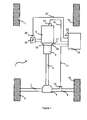
- a motor vehicle drive 1 shown schematically in Figure 1 comprises a motor 2, an air inlet flap (throttle valve of a throttle body) 25 and a gearbox 3 which is connected, via a clutch 5 and, for example by a cardan shaft or an articulated shaft 4, to an axle gear train 6 (the axle rear in figure 1.)
- the axle gear train 6, or differential is itself connected by axle shafts 7 and 8 to drive wheels 9 and 10, respectively.
- the front wheels 11 and 12 are not driven. However, in other modes of realization, it is the front wheels 11 and 12 which are driving or all the wheels of the vehicle 1 are driven.
- a first rotation speed sensor 14 is used to determine the rotation speed of the motor N and produces a signal representative of the speed of rotation of the motor.
- Speed of rotation of motor N coincides with the speed of rotation of an input shaft (not shown) of the gearbox 3.
- a second speed sensor 15 is used to determine the speed of rotation at the output of the gearbox V.
- the sensor speed at the output of the gearbox can be configured in several ways, depending on the equipment with which the vehicle is to be fitted.
- the sensor 15 includes an odometer at the output of the gearbox. According to a variant shown in FIG.
- the sensor 15 picks up the speed of rotation of at least one wheel (preferably a driving wheel) and produces a signal representative of the speed of the vehicle 1 which, taking account of the gear ratio in the axle gear train 6, is practically proportional to the speed of rotation V of the output shaft of the gearbox speed 3.
- One of the means to achieve such a variant consists in using measurements of wheel rotation speed from an anti-lock device and to perform the average of these measurements for the driving wheels or for all the wheels.
- the signals from the rotational speed sensors 14 and 15 are transmitted by lines 16 and 17, respectively, to an engine control computer 18.
- this sensor 26 transmits to the computer 18 a signal representative of the position of the throttle valve, on a line 27.
- this sensor 20 transmits to the computer 18 a signal representative of the position of the clutch 5 on a line 21.
- a such a clutch sensor 20 is a start-of-travel sensor rather than an end-of-travel sensor race to limit delays in detecting pedal position change Clutch.
- Other control and signal lines 22 can connect the computer 18 to various other sensors and actuators in the vehicle, for example, a control ignition and / or an injection command.
- the computer 18 determines the instantaneous value (possibly filtered) of the N / V ratio, select a set of limit values, and compare the N / V ratio to the limit values of the set of selected limit value.
- the computer 18 puts uses the flow diagram illustrated in FIG. 4. It can be seen that, throughout the description, not only considers the gear ratios corresponding to the different gearbox reports, but also a gearbox report "0" which is said to be “engaged” either when no gearbox ratio is not engaged (neutral) either when the clutch is uncoupled. So, switching from one gearbox to another involves two gear changes engaged.
- the computer 18 detects the release of this ratio (engagement of a ratio 0 - zero) when the N / V ratio leaves the set of limit values selected for a period T1 (fig.5) called "confirmation".
- the computer 18 selects the narrow set of limit values associated with the ratio of reduction previously engaged and the set of wide limit values for the others gearbox reports.
- the computer 18 determines the engagement of a new report when, for a period T2 (fig.5) called “validation", the N / V ratio enters and remains between the limit values of the set of limit values selected for said gear ratio.
- the validation, confirmation and selection times are, for example, each between 100 to 200 ms.
- each gearbox report is associated with a set of "narrow" limit values with a lower limit value close to the nominal value for said gear ratio, 308, 318, 328, 338 and 348, respectively, and a limit value upper close to the nominal value for said ratio, 312, 322, 332, 342 and 352, respectively.
- Each gearbox report is also associated with a set of "wide" limit values comprising a lower limit value far from the nominal value for said ratio, 306, 316, 326, 336 and 346, respectively, and an upper limit far from the nominal value for said ratio, 314, 324, 334, 344 and 354, respectively.
- the wide upper limit value associated with a ratio can be greater than the wide lower limit value associated with the next report.
- the threshold 344 is greater than threshold 346.
- step 404 it is detected whether a gear is engaged in determining if the ratio of rotation speeds at the input of gearbox N and at output of gearbox V, is between two limit values of a set of limit values selected corresponding to a gearbox report, during a validation period predetermined, for example 200 ms. Otherwise, step 404 is repeated. If yes, during a step 406, it stores in a second register retaining the gearbox ratio engaged the report corresponding to the set of limit values between which is the ratio N / V. For example, if the first gear is engaged, we memorize "1" in the second register.
- the wide limit value set is selected corresponding to the gearbox engaged.
- a step 410 it is detected whether a declutching takes place by determining whether, during a confirmation period, for example 150 ms., the N / V ratio exceeds one of the limit values for the set of limit values selected. Yes yes, during a step 412, we transfer the gearbox stored in the second register to the first register (previous gearbox engaged) and we store "0" in the second register to signify that no gearbox report is engaged. Then at during a step 414, all the sets of wide limit values are selected, except for the previous gearbox report engaged for which the narrow limit value set is selected.
- a step 416 it is determined whether the engine is stopped. If yes, the operation of the computer is stopped, step 418, and if not, step 404 is repeated.
- a clutch release was not detected during step 410, during a step 420, it is detected whether the engine speed is stable by determining whether, during a period of predetermined selection, for example 100 ms., the absolute value of the derivative with respect to at the time of the speed of rotation at the input of the box does not exceed a predetermined threshold and if, during the selection period, the derivative with respect to time of the speed of rotation at the input of the box retains its sign, that is to say that the speed of rotation at the input of box remains increasing or decreasing.
- a period of predetermined selection for example 100 ms.
- step 426 we select the set of wide limit values corresponding to the gearbox engaged, then we repeats step 410. If the two conditions of step 420 are met, during a step 422, it is determined whether either the throttle valve is closed or the state of the engine is neither at full load or partial load. If one of the conditions of step 422 is met, during from a step 424, we select the set of narrow limit values for the gear ratio engaged then step 410 is repeated. If none of the conditions of step 422 are met, performs step 426.
- the N / V ratio is filtered so as not to keep than low frequencies, for example less than 10 Hz or 20 Hz, before determine if the filtered N / V ratio is between two limit values selected during the predetermined validation period.
- the gain of the filter depends on the speed N and the gearbox report currently engaged.
- a first upper line 510 indicates that, during the predetermined selection period, the absolute value of the derivative with respect to the time (or gradient) of the speed at the input of the gearbox did not exceed a threshold predetermined and that, during the selection period, the derivative with respect to the time of the speed at the input of the gearbox has kept its sign, high state or, that one of these conditions have not been met, low condition.
- a second upper line 520 indicates whether either the throttle valve is in the closed position or the state of the engine is neither fully loaded nor partially loaded, high condition, or if none of these conditions are not met, low condition.
- a graph 590 represents the gearbox ratio detected by setting work of the embodiment of the invention illustrated in Figures 1 to 4, the ratio "0" representing the absence of a committed report, "1" (respectively "2") representing the detection that the first (respectively the second) gearbox is engaged.
- a graph 530 comprises a curve of N / V ratio values 540, a set of wide limit values 550 assigned to a first gear ratio, a set of limit values narrow 560 assigned to the first gear ratio, a set of wide limit values 570 assigned to a second gear ratio, a narrow set of limit values 580 assigned to this second gearbox ratio and, in broken lines, the limit values of the set or sets of values limits selected at all times.
- the N / V ratio crosses the selected upper limit value. If, like in Figure 5, during the confirmation period T1 following time t1, the N / V ratio is greater than the upper limit value selected, at time t1 + T1, the computer determines that no gearbox report is no longer engaged (the report "0" then being "engaged”.)
- the narrow limit value set is selected for the first gear ratio, which has just been disengaged, and the wide limit value set is selected for the second gear report.
- the N / V ratio crosses the value lower limit of the set of limit values selected for the second gear ratio.
- the ratio N / V remains between the limit values of the set of limit values selected for the second gearbox report. Consequently, at time t2 + T2, the computer determines that the second gear report is engaged.
- a graph 630 comprises a curve of N / V ratio values 640, a set narrow limit values 650 assigned to the first gear ratio, a set of limit values wide 660 assigned to the first gear ratio and, in broken lines, the limit values of set of limit values selected at all times.
- the confirmation or validation times vary depending on the gearbox engaged.
- the validation time varies depending on the gearbox ratio detected (when detecting a )
- the filters used to filter the N / V ratio depend on the engine speed N, gearbox engaged (to detect a clutch) and / or gear transmission detected (during a clutch.)
- the potential limit values used to detect a clutch are different from the potential limit values used to detect a clutch.
- a set of limit values is selected more close to the nominal value corresponding to the predetermined reduction ratio that when the engine condition is at least partially loaded.
Landscapes
- Engineering & Computer Science (AREA)
- General Engineering & Computer Science (AREA)
- Mechanical Engineering (AREA)
- Control Of Transmission Device (AREA)
Abstract
caractérisé en ce qu'il comporte une opération de sélection (402, 408, 414, 420, 422, 424, 426) au cours de laquelle, pour au moins un rapport de boíte, on sélectionne le jeu de valeurs limites entre au moins deux jeux de valeurs limites potentiels.
Description
caractérisé en ce qu'il comporte une opération de sélection au cours de laquelle, pour au moins un rapport de boíte, on sélectionne le jeu de valeurs limites entre au moins deux jeux de valeurs limites potentielles.
caractérisé en ce qu'il comporte un moyen de sélection de jeu de valeurs limites qui, pour au moins un rapport de boíte, sélectionne le jeu de valeurs limites entre au moins deux jeux de valeurs limites potentielles.
- plus de deux jeux de valeurs limites sont utilisés pour au moins un rapport de boíte,
- au moins un jeu de valeurs limites progressivement variables en fonction de l'une au moins des vitesses d'entrée ou de sortie de boíte est utilisé et/ou
- au moins un jeu de valeurs limites progressivement variables dans le temps en fonction de paramètres de fonctionnement du moteur est utilisé.
- le papillon de gaz est fermé ou l'état du moteur n'est ni en pleine charge ni en charge partielle,
- la valeur absolue de la dérivée par rapport au temps de la vitesse de rotation en entrée de boíte n'a pas excédé un seuil prédéterminé pendant une durée de sélection prédéterminée, et
- pendant la durée de sélection, la dérivée par rapport au temps de la vitesse de rotation en entrée de boíte a conservé son signe, c'est-à-dire que la vitesse de rotation en entrée de boíte est restée croissante ou décroissante.
Claims (10)
- Procédé de reconnaissance du rapport engagé d'une boíte de vitesses (3) d'un véhicule automobile (1), procédé mettant en oeuvre un signal correspondant à la vitesse de rotation d'entrée de la boíte et un signal correspondant à la vitesse de rotation de sortie de la boíte, comportant une opération de détermination d'engagement de rapport (404) au cours de laquelle on détermine quel rapport de boíte est engagé, en fonction de la position relative du ratio desdits signaux et de valeurs limites d'au moins un jeu de valeurs limites, chaque jeu de valeurs limites correspondant à un rapport de boíte ;
caractérisé en ce qu'il comporte une opération de sélection (402, 408, 414, 420, 422, 424, 426) au cours de laquelle, pour au moins un rapport de boíte, on sélectionne le jeu de valeurs limites entre au moins deux jeux de valeurs limites potentiels (306, 308, 312, 314, 316, 318, 322, 324, 326, 328, 332, 334, 336, 338, 342, 344, 346, 348, 352, 354.) - Procédé selon la revendication 1, caractérisé en ce qu'au cours de l'opération de sélection de ladite valeur limite (422), on met en oeuvre une position d'un volet d'entrée d'air d'un boítier papillon ou la charge du moteur, et lorsque :le papillon est fermé ou que l'état du moteur n'est ni en pleine charge ni en charge partielle,la valeur absolue de la dérivée par rapport au temps de la vitesse de rotation en entrée de boíte n'a pas excédé un seuil prédéterminé pendant une durée dite "de sélection" etpendant la durée de sélection, la dérivée par rapport au temps de la vitesse de rotation en entrée de boíte a conservé son signe, c'est-à-dire que la vitesse de rotation en entrée de boíte est restée croissante ou décroissante,on sélectionne un jeu de valeurs limites plus proches de la valeur nominale correspondant au rapport de démultiplication prédéterminé que lorsque aucune de ces conditions n'est remplie.
- Procédé selon l'une quelconque des revendications 1 ou 2, caractérisé en ce qu'au cours de l'opération de sélection de ladite valeur limite (422), on met en oeuvre une position d'un volet d'entrée d'air d'un boítier papillon ou la charge du moteur, et lorsque :le papillon est ouvert ou que l'état du moteur est soit en pleine charge soit en charge partielle,la valeur absolue de la dérivée par rapport au temps de la vitesse de rotation en entrée de boíte n'a pas excédé un seuil prédéterminé pendant une durée dite "de sélection" etpendant la durée de sélection, la dérivée par rapport au temps de la vitesse de rotation en entrée de boíte a conservé son signe, c'est-à-dire que la vitesse de rotation en entrée de boíte est restée croissante ou décroissante,on sélectionne un jeu de valeurs limites plus éloignées de la valeur nominale correspondant au rapport de démultiplication prédéterminé que lorsque aucune de ces conditions n'est remplie.
- Procédé selon l'une quelconque des revendications 1 à 3, caractérisé en ce qu'au cours de l'opération de sélection de ladite valeur limite (422), on met en oeuvre une position d'un volet d'entrée d'air d'un boítier papillon, ou papillon de gaz, et lorsque le papillon est fermé, on sélectionne un jeu de valeurs limites plus proches de la valeur nominale correspondant au rapport de démultiplication prédéterminé que lorsque le papillon de gaz est ouvert.
- Procédé selon l'une quelconque des revendications 1 à 4, caractérisé en ce qu'au cours de l'opération de sélection de ladite valeur limite (422), on met en oeuvre la charge du moteur et lorsque l'état moteur n'est ni en pleine charge ni en charge partielle, on sélectionne un jeu de valeurs limites plus proches de la valeur nominale correspondant au rapport de démultiplication prédéterminé que lorsque l'état moteur est au moins à charge partielle.
- Procédé selon l'une quelconque des revendications 1 à 5, caractérisé en ce qu'au cours de l'opération de sélection de ladite valeur limite (420), on teste si la valeur absolue de la dérivée par rapport au temps de la vitesse de rotation en entrée de boíte n'a pas excédé un seuil prédéterminé pendant une durée dite "de sélection" et si, pendant la durée de sélection, la dérivée par rapport au temps de la vitesse de rotation en entrée de boíte a conservé son signe, c'est-à-dire que la vitesse de rotation en entrée de boíte est restée croissante ou décroissante, et, lorsque ces deux conditions sont remplies, on sélectionne un jeu de valeurs limites plus proches de la valeur nominale correspondant au rapport de démultiplication prédéterminé que lorsque aucune de ces conditions n'est remplie.
- Procédé selon l'une quelconque des revendications 1 à 6, caractérisé en ce qu'il comporte, lorsqu'il a été détecté qu'aucun rapport de boíte n'est engagé, une opération de validation de rapport de boíte engagé (404) au cours de laquelle on détermine qu'un rapport de boíte est engagé lorsque, pendant une durée dite "de validation", pour ledit rapport de boíte, ledit ratio reste entre deux valeurs limites du jeu de valeurs limites sélectionné pour ledit rapport de boíte.
- Procédé selon l'une quelconque des revendications 1 à 7, caractérisé en ce que, lorsqu'il a été détecté qu'un rapport de boíte est engagé, au cours de l'opération de sélection, on sélectionne un jeu de deux valeurs limites, l'une supérieure à la valeur nominale correspondant audit rapport de boíte et l'autre inférieure à ladite valeur nominale correspondant audit rapport, chacune des deux valeurs limites étant sélectionnée entre au moins deux valeurs limites potentielles.
- Procédé selon l'une quelconque des revendications 1 à 8, caractérisé en ce que lorsqu'il a été détecté qu'aucun rapport de boíte n'est engagé, au cours de l'opération de sélection, on sélectionne un jeu de valeurs limites pour chaque rapport de boíte, les valeurs limites du jeu de valeurs limites sélectionné pour le précédent rapport de boíte engagé étant plus proches de la valeur nominale correspondant au rapport de démultiplication prédéterminé que les valeurs limites du jeu de valeurs limites sélectionné pour les autres rapports de boíte.
- Dispositif de reconnaissance du rapport engagé d'une boíte de vitesses (3) d'un véhicule automobile (1), comportant un capteur de vitesse de rotation d'entrée de boíte fournissant un signal correspondant à la vitesse de rotation d'entrée de la boíte (14) et un capteur de vitesse de rotation de sortie de boíte (15) fournissant un signal correspondant à la vitesse de rotation de sortie de la boíte, comportant un moyen de détermination d'engagement de rapport (18) qui détermine quel rapport de boíte est engagé, en fonction de la position relative du ratio desdits signaux et de valeurs limites d'au moins un jeu de valeurs limites, chaque jeu de valeurs limites correspondant à un rapport de boíte ;
caractérisé en ce qu'il comporte un moyen de sélection (18) de jeu de valeurs limites qui, pour au moins un rapport de boíte, sélectionne le jeu de valeurs limites entre au moins deux jeux de valeurs limites potentiels.
Applications Claiming Priority (2)
| Application Number | Priority Date | Filing Date | Title |
|---|---|---|---|
| FR0107967 | 2001-06-18 | ||
| FR0107967A FR2826087A1 (fr) | 2001-06-18 | 2001-06-18 | Procede et dispositif de reconnaissance de rapport de boite de vitesses |
Publications (3)
| Publication Number | Publication Date |
|---|---|
| EP1271005A2 true EP1271005A2 (fr) | 2003-01-02 |
| EP1271005A3 EP1271005A3 (fr) | 2009-05-06 |
| EP1271005B1 EP1271005B1 (fr) | 2011-07-27 |
Family
ID=8864444
Family Applications (1)
| Application Number | Title | Priority Date | Filing Date |
|---|---|---|---|
| EP20020011656 Expired - Lifetime EP1271005B1 (fr) | 2001-06-18 | 2002-05-31 | Procédé et dispositif de reconnaissance de rapport de boite de vitesses |
Country Status (2)
| Country | Link |
|---|---|
| EP (1) | EP1271005B1 (fr) |
| FR (1) | FR2826087A1 (fr) |
Cited By (6)
| Publication number | Priority date | Publication date | Assignee | Title |
|---|---|---|---|---|
| EP2128497A1 (fr) * | 2008-05-28 | 2009-12-02 | C.R.F. Società Consortile per Azioni | Procédé pour la surveillance du changement de vitesses dans un véhicule à moteur doté d'une transmission à embrayage double |
| US20150345618A1 (en) * | 2014-06-02 | 2015-12-03 | Honda Motor Co., Ltd. | Transmission |
| DE102015213613A1 (de) * | 2015-07-20 | 2017-01-26 | Volkswagen Aktiengesellschaft | Sensorlose Istgang-Modellierung |
| CN110185794A (zh) * | 2018-02-22 | 2019-08-30 | 舍弗勒技术股份两合公司 | 用于在车辆中的手动换挡变速器中进行挡位识别的方法 |
| CN112460251A (zh) * | 2020-12-08 | 2021-03-09 | 安徽江淮汽车集团股份有限公司 | 柴油车辆及其档位识别方法和计算机可读存储介质 |
| CN115182995A (zh) * | 2022-06-30 | 2022-10-14 | 东风商用车有限公司 | 一种手动变速箱档位判断方法及系统 |
Families Citing this family (2)
| Publication number | Priority date | Publication date | Assignee | Title |
|---|---|---|---|---|
| FR2861155B1 (fr) * | 2003-10-17 | 2005-12-16 | Siemens Vdo Automotive | Procede de determination du rapport engage dans une boite de vitesses |
| CN112989502B (zh) * | 2019-12-12 | 2025-08-26 | 厦门雅迅智联科技股份有限公司 | 变速箱档位数和传动比的计算方法及存储介质 |
Family Cites Families (4)
| Publication number | Priority date | Publication date | Assignee | Title |
|---|---|---|---|---|
| EP0424370B1 (fr) * | 1988-07-01 | 1993-09-29 | Robert Bosch Gmbh | Systeme de commande pour vehicule avec transmission automatique |
| JP2959938B2 (ja) * | 1993-08-31 | 1999-10-06 | 本田技研工業株式会社 | 車両用自動変速機の制御装置 |
| DE4333822A1 (de) * | 1993-10-04 | 1995-04-06 | Bosch Gmbh Robert | Verfahren und Vorrichtung zur Gangerkennung bei einem Kraftfahrzeug |
| DE19630937C2 (de) * | 1996-07-31 | 2000-05-25 | Siemens Ag | Verfahren und Schaltungsanordnung zur Gangerkennung in einem Getriebe eines Kraftfahrzeugs |
-
2001
- 2001-06-18 FR FR0107967A patent/FR2826087A1/fr not_active Withdrawn
-
2002
- 2002-05-31 EP EP20020011656 patent/EP1271005B1/fr not_active Expired - Lifetime
Cited By (14)
| Publication number | Priority date | Publication date | Assignee | Title |
|---|---|---|---|---|
| EP2428701A1 (fr) * | 2008-05-28 | 2012-03-14 | C.R.F. Società Consortile per Azioni | Procédé pour la surveillance du changement de vitesse dans un véhicule à moteur doté d'une transmission à embrayage double |
| US8255131B2 (en) | 2008-05-28 | 2012-08-28 | C.R.F. Societa Consortile Per Azioni | Method for monitoring a gear-change operation in a motor vehicle provided with a dual-clutch transmission |
| EP2128497A1 (fr) * | 2008-05-28 | 2009-12-02 | C.R.F. Società Consortile per Azioni | Procédé pour la surveillance du changement de vitesses dans un véhicule à moteur doté d'une transmission à embrayage double |
| US9951863B2 (en) | 2014-06-02 | 2018-04-24 | Honda Motor Co., Ltd. | Transmission |
| US20150345618A1 (en) * | 2014-06-02 | 2015-12-03 | Honda Motor Co., Ltd. | Transmission |
| EP2952782A1 (fr) * | 2014-06-02 | 2015-12-09 | Honda Motor Co., Ltd. | Transmission with gear ratio calculating means |
| JP2015227713A (ja) * | 2014-06-02 | 2015-12-17 | 本田技研工業株式会社 | 変速機 |
| DE102015213613A1 (de) * | 2015-07-20 | 2017-01-26 | Volkswagen Aktiengesellschaft | Sensorlose Istgang-Modellierung |
| CN110185794A (zh) * | 2018-02-22 | 2019-08-30 | 舍弗勒技术股份两合公司 | 用于在车辆中的手动换挡变速器中进行挡位识别的方法 |
| CN110185794B (zh) * | 2018-02-22 | 2022-06-07 | 舍弗勒技术股份两合公司 | 用于在车辆中的手动换挡变速器中进行挡位识别的方法 |
| CN112460251A (zh) * | 2020-12-08 | 2021-03-09 | 安徽江淮汽车集团股份有限公司 | 柴油车辆及其档位识别方法和计算机可读存储介质 |
| CN112460251B (zh) * | 2020-12-08 | 2022-06-14 | 安徽江淮汽车集团股份有限公司 | 柴油车辆及其档位识别方法和计算机可读存储介质 |
| CN115182995A (zh) * | 2022-06-30 | 2022-10-14 | 东风商用车有限公司 | 一种手动变速箱档位判断方法及系统 |
| CN115182995B (zh) * | 2022-06-30 | 2024-06-04 | 东风商用车有限公司 | 一种手动变速箱档位判断方法及系统 |
Also Published As
| Publication number | Publication date |
|---|---|
| EP1271005B1 (fr) | 2011-07-27 |
| EP1271005A3 (fr) | 2009-05-06 |
| FR2826087A1 (fr) | 2002-12-20 |
Similar Documents
| Publication | Publication Date | Title |
|---|---|---|
| EP2126319B1 (fr) | Procede de controle du fonctionnement d'un groupe moto-propulseur | |
| FR2645805A1 (fr) | Procede de commande d'un embrayage a friction automatise agissant entre un moteur d'entrainement et une transmission, appareillage pour la mise en oeuvre du procede, et regulation associee d'un embrayage a friction | |
| FR2797499A1 (fr) | Procede de mise en oeuvre d'un vehicule | |
| FR2785353A1 (fr) | Vehicule a moteur a identification d'intention de commutation | |
| FR2742502A1 (fr) | Vehicule automobile a systeme automatise de transmission de couple | |
| FR2791749A1 (fr) | Procede et dispositif pour determiner le point d'attaque d'un embrayage assiste | |
| FR2706376A1 (fr) | Procédé de commande automatique d'un embrayage pour déclencher et interrompre des phases de roulement en poussée dans un véhicule automobile. | |
| EP1271005B1 (fr) | Procédé et dispositif de reconnaissance de rapport de boite de vitesses | |
| FR2742387A1 (fr) | Dispositif d'actionnement d'un systeme de transmission d'un couple de rotation | |
| FR2661374A1 (fr) | Dispositif d'actionnement d'un embrayage a friction pour vehicule automobile. | |
| FR2752031A1 (fr) | Procede et agencement de circuit pour la reconnaissance de vitesse dans une boite de vitesses d'un vehicule automobile | |
| FR2632905A1 (fr) | Procede destine a eviter les battements d'inversion de charge | |
| FR2695084A1 (fr) | Dispositif de commande d'un embrayage à friction de véhicule automobile. | |
| EP1510717B1 (fr) | Procédé pour sélectionner une loi de commande du système de pilotage d'un embrayage en déterminant trois points de fonctionnement | |
| FR2697884A1 (fr) | Dispositif de commutation pour une boîte de vitesses. | |
| FR2859263A1 (fr) | Systeme de reduction de choc de changement de vitesse d'une boite de vitesses automatique | |
| FR2772865A1 (fr) | Procede de detection des sols glissants et du blocage des roues de vehicule, transmission automatique mettant en oeuvre le procede et vehicule dote d'une telle transmission | |
| FR2893293A1 (fr) | Procede de liberation automatique du frein d'un vehicule avec un temps de liberation optimun | |
| FR2789023A1 (fr) | Procede pour effectuer des operations de commutation d'un systeme d'entrainement | |
| FR2770465A1 (fr) | Procede et dispositif de determination du patinage dans un embrayage | |
| FR2897318A1 (fr) | Procede pour commander le systeme de la chaine motrice d'un vehicule automobile | |
| FR3130235A1 (fr) | Procede de correction de la mesure de position d’une pedale d’embrayage | |
| WO2004010031A2 (fr) | Procede et dispositif de commande d'une transmission automatique equipant un vehicule en situation de montee | |
| EP1673559B1 (fr) | Procede de determination du rapport engage dans une boite de vitesses | |
| EP3870828B1 (fr) | Procédé de gestion d'un arrêt automatique du moteur thermique en fonction d'une activité sur une pédale de frein |
Legal Events
| Date | Code | Title | Description |
|---|---|---|---|
| PUAI | Public reference made under article 153(3) epc to a published international application that has entered the european phase |
Free format text: ORIGINAL CODE: 0009012 |
|
| AK | Designated contracting states |
Kind code of ref document: A2 Designated state(s): AT BE CH CY DE DK ES FI FR GB GR IE IT LI LU MC NL PT SE TR |
|
| AX | Request for extension of the european patent |
Free format text: AL;LT;LV;MK;RO;SI |
|
| RAP1 | Party data changed (applicant data changed or rights of an application transferred) |
Owner name: CONTINENTAL AUTOMOTIVE FRANCE |
|
| PUAL | Search report despatched |
Free format text: ORIGINAL CODE: 0009013 |
|
| AK | Designated contracting states |
Kind code of ref document: A3 Designated state(s): AT BE CH CY DE DK ES FI FR GB GR IE IT LI LU MC NL PT SE TR |
|
| AX | Request for extension of the european patent |
Extension state: AL LT LV MK RO SI |
|
| 17P | Request for examination filed |
Effective date: 20091106 |
|
| AKX | Designation fees paid |
Designated state(s): FR |
|
| REG | Reference to a national code |
Ref country code: DE Ref legal event code: 8566 |
|
| GRAP | Despatch of communication of intention to grant a patent |
Free format text: ORIGINAL CODE: EPIDOSNIGR1 |
|
| GRAS | Grant fee paid |
Free format text: ORIGINAL CODE: EPIDOSNIGR3 |
|
| GRAA | (expected) grant |
Free format text: ORIGINAL CODE: 0009210 |
|
| AK | Designated contracting states |
Kind code of ref document: B1 Designated state(s): FR |
|
| PLBE | No opposition filed within time limit |
Free format text: ORIGINAL CODE: 0009261 |
|
| STAA | Information on the status of an ep patent application or granted ep patent |
Free format text: STATUS: NO OPPOSITION FILED WITHIN TIME LIMIT |
|
| 26N | No opposition filed |
Effective date: 20120502 |
|
| REG | Reference to a national code |
Ref country code: FR Ref legal event code: PLFP Year of fee payment: 15 |
|
| REG | Reference to a national code |
Ref country code: FR Ref legal event code: PLFP Year of fee payment: 16 |
|
| REG | Reference to a national code |
Ref country code: FR Ref legal event code: PLFP Year of fee payment: 17 |
|
| PGFP | Annual fee paid to national office [announced via postgrant information from national office to epo] |
Ref country code: FR Payment date: 20180522 Year of fee payment: 17 |
|
| PG25 | Lapsed in a contracting state [announced via postgrant information from national office to epo] |
Ref country code: FR Free format text: LAPSE BECAUSE OF NON-PAYMENT OF DUE FEES Effective date: 20190531 |