EP1270315A2 - Vehicle seat positioned on the floor - Google Patents
Vehicle seat positioned on the floor Download PDFInfo
- Publication number
- EP1270315A2 EP1270315A2 EP02012698A EP02012698A EP1270315A2 EP 1270315 A2 EP1270315 A2 EP 1270315A2 EP 02012698 A EP02012698 A EP 02012698A EP 02012698 A EP02012698 A EP 02012698A EP 1270315 A2 EP1270315 A2 EP 1270315A2
- Authority
- EP
- European Patent Office
- Prior art keywords
- vehicle seat
- diagonal strut
- seat frame
- front foot
- seat according
- Prior art date
- Legal status (The legal status is an assumption and is not a legal conclusion. Google has not performed a legal analysis and makes no representation as to the accuracy of the status listed.)
- Withdrawn
Links
Images


Classifications
-
- B—PERFORMING OPERATIONS; TRANSPORTING
- B60—VEHICLES IN GENERAL
- B60N—SEATS SPECIALLY ADAPTED FOR VEHICLES; VEHICLE PASSENGER ACCOMMODATION NOT OTHERWISE PROVIDED FOR
- B60N2/00—Seats specially adapted for vehicles; Arrangement or mounting of seats in vehicles
- B60N2/24—Seats specially adapted for vehicles; Arrangement or mounting of seats in vehicles for particular purposes or particular vehicles
- B60N2/30—Non-dismountable or dismountable seats storable in a non-use position, e.g. foldable spare seats
- B60N2/3038—Cushion movements
- B60N2/3063—Cushion movements by composed movement
- B60N2/3065—Cushion movements by composed movement in a longitudinal-vertical plane
-
- B—PERFORMING OPERATIONS; TRANSPORTING
- B60—VEHICLES IN GENERAL
- B60N—SEATS SPECIALLY ADAPTED FOR VEHICLES; VEHICLE PASSENGER ACCOMMODATION NOT OTHERWISE PROVIDED FOR
- B60N2/00—Seats specially adapted for vehicles; Arrangement or mounting of seats in vehicles
- B60N2/005—Arrangement or mounting of seats in vehicles, e.g. dismountable auxiliary seats
- B60N2/015—Attaching seats directly to vehicle chassis
- B60N2/01508—Attaching seats directly to vehicle chassis using quick release attachments
- B60N2/01516—Attaching seats directly to vehicle chassis using quick release attachments with locking mechanisms
- B60N2/01583—Attaching seats directly to vehicle chassis using quick release attachments with locking mechanisms locking on transversal elements on the vehicle floor or rail, e.g. transversal rods
-
- B—PERFORMING OPERATIONS; TRANSPORTING
- B60—VEHICLES IN GENERAL
- B60N—SEATS SPECIALLY ADAPTED FOR VEHICLES; VEHICLE PASSENGER ACCOMMODATION NOT OTHERWISE PROVIDED FOR
- B60N2/00—Seats specially adapted for vehicles; Arrangement or mounting of seats in vehicles
- B60N2/24—Seats specially adapted for vehicles; Arrangement or mounting of seats in vehicles for particular purposes or particular vehicles
- B60N2/30—Non-dismountable or dismountable seats storable in a non-use position, e.g. foldable spare seats
- B60N2/3002—Non-dismountable or dismountable seats storable in a non-use position, e.g. foldable spare seats back-rest movements
- B60N2/3004—Non-dismountable or dismountable seats storable in a non-use position, e.g. foldable spare seats back-rest movements by rotation only
- B60N2/3009—Non-dismountable or dismountable seats storable in a non-use position, e.g. foldable spare seats back-rest movements by rotation only about transversal axis
- B60N2/3011—Non-dismountable or dismountable seats storable in a non-use position, e.g. foldable spare seats back-rest movements by rotation only about transversal axis the back-rest being hinged on the cushion, e.g. "portefeuille movement"
-
- B—PERFORMING OPERATIONS; TRANSPORTING
- B60—VEHICLES IN GENERAL
- B60N—SEATS SPECIALLY ADAPTED FOR VEHICLES; VEHICLE PASSENGER ACCOMMODATION NOT OTHERWISE PROVIDED FOR
- B60N2/00—Seats specially adapted for vehicles; Arrangement or mounting of seats in vehicles
- B60N2/24—Seats specially adapted for vehicles; Arrangement or mounting of seats in vehicles for particular purposes or particular vehicles
- B60N2/30—Non-dismountable or dismountable seats storable in a non-use position, e.g. foldable spare seats
- B60N2/3088—Non-dismountable or dismountable seats storable in a non-use position, e.g. foldable spare seats characterised by the mechanical link
- B60N2/309—Non-dismountable or dismountable seats storable in a non-use position, e.g. foldable spare seats characterised by the mechanical link rods
Definitions
- the invention relates to a vehicle seat, in particular a motor vehicle seat the features of the preamble of claim 1.
- the backrest structure is used for a table position folded onto the seat frame so that the back of the backrest is horizontal is aligned. If this increase in the loading area is not sufficient, it can the vehicle seat as a whole can be removed. Such a vehicle seat leaves in the Practice still open to wishes.
- the invention is based on the object of a vehicle seat of the type mentioned Kind of improve. This object is achieved by a vehicle seat solved with the features of claim 1.
- Advantageous configurations are the subject of the subclaims.
- the diagonal strut is releasably locked to the front foot area, i.e. a releasable locking device is provided which the diagonal strut and locked the front foot area together, can easily Shape of the seat frame and thus the position of the vehicle seat can be changed.
- the locked diagonal strut keeps the seat frame stable while when the diagonal strut is unlocked, it is designed, for example, as a four-bar linkage Seat frame is foldable, in particular can be folded flat. With one Floor position, the vehicle seat no longer needs to be removed to the loading area to enlarge.
- the front foot area preferably has a guide for controlled movement of the diagonal strut. It is usually symmetrical Force distribution on each side of the vehicle seat is a diagonal strut is provided, the two diagonal struts for stability reasons by at least a common, horizontal traverse are interconnected.
- the front foot area for locking the Diagonal strut provided a locking hook, which is a bolt and / or Traverse of the diagonal strut at least partially encompasses, preferably positively.
- This bolt or this cross member preferably forms the one at the same time Component, which is in the guide for the diagonal strut of the front Foot area is guided.
- the spring-loaded, for example, designed to be pivotable Locking hook is, for example, manual over various unlocking elements, such as hand straps, swiveling levers or shafts, from the bolt or the Crossbar removable.
- the invention is particularly advantageous for rear rows of seats in a so-called van. Due to the flat, usually recessed floor position, the loading area can of the van can be greatly enlarged without the vehicle seat being removed got to. With the configuration according to the invention, simple operation is available Available. However, the invention can also be used for other vehicles.
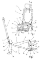
- a vehicle seat 1 is a motor vehicle rear seat, preferably for a third row of seats a so-called van.
- the vehicle seat 1 has a seat frame 3 as a seat part structure on which by means of two backrest pivot bolts aligned with one another 5 a backrest structure 7 of a backrest is articulated.
- the Seat frame 3 carries a seat cushion, not shown, in a manner known per se. Regarding the direction of travel on the left and on the right, this indicates Seat frame 3 each have a seat frame side part 9, in each of which one of the backrest pivot bolts 5 is stored.
- the two seat frame side parts 9 are in theirs front area by a front seat frame cross member 11 and in its rear Area through a rear seat frame cross member 13 to form a Seat frame firmly connected. Below is the seating position of the vehicle seat 1 described.
- a front Swing arm 15 with its upper end articulated, which with its lower end a front bearing block 17 fixed to the vehicle structure is articulated.
- the front one Swing arm 15 and the front bracket 17 form a front foot portion of the Seat frame 3.
- the two front wings 15 are by a cross arm 19 firmly connected.
- a rear swing arm 23 articulated at its upper end, which at its lower end is attached to a vehicle structure-fixed rear bracket 25 is articulated.
- On the seat frame side parts 9 are in the area between the respective backrest pivot pin 5 and the rear seat frame cross member 13 each have backrest locks 27 attached, which backrest locking bolts 29 which are fixed to the backrest structure by means of hooks lock.
- each of the rear seat frame cross members 13 articulated with its rear end.
- the two diagonal struts 31 are in the area its front end by a load-bearing diagonal strut cross member 33 and by means of a locking cross member 35, which is preferably designed as a rod connected.
- the locking cross member 35 is closer to one below locked way described with the front bearing block 17. Every end of the Locking cross member 35 is in each case within a guide 37 of the associated front rocker 15 arranged.
- the firmly connected to the front rocker 15 Guide 37 is formed with a U-shaped profile and runs along the front rocker 15 perpendicular to the locking cross member 35.
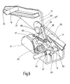
- each front bearing block 17 there is a locking hook 41 as a locking device pivoted, which by acting on a leg spring 43 the Locking cross member 35 engages at least partially and locked in a form-fitting manner.
- a cam 45 is mounted, from which a driver pin 47 projects laterally.
- the driver pin 47 is encompassed by a driver clip 49, which sits non-rotatably on an unlocking crossbar 51 designed as a rod.
- the unlocking cross member 51 is rotatable in one of the two ends front bearing blocks 17 stored. On the unlocking crossbar 51 sits on one End rotatably a release lever 53, which can be gripped manually Unlocking loop 55 is provided.
- each front bracket 17 an elongated bolt 61 is also pivotally mounted.
- a tension spring 63 which on a laterally projecting from the bolt 61 pin 65 attacks, the bolt 61 biases towards a control disc 67.
- the control disc 67 is seated on a rocker arm pivot pin with respect to the front rocker 15 69, which is the articulation point of the front rocker 15 on the front Bearing block 17 forms.
- a connecting lever 71 which at one end by means of a Langlochs encloses the pin 65, is at its other end on the release lever 53 articulated.
- the vehicle seat 1 can in addition to the seating position described above occupy further positions.
- the back locks 27 are unlocked so that the back lock bolts 29 are released.
- the backrest structure 7 can then around the backrest pivot pin 5 forward into an at least approximately horizontal position be folded.
- the back of the backrest then serves as a loading area.
- the seat frame 3 by locking the locking crossbar 35 of the diagonal struts 31 are dimensionally stable, that is to say immovable. Due to the selected arrangement of the diagonal struts 31 obliquely to the front and In the event of a crash, the forces acting on the backrest are shown below in the vehicle structure initiated.
- the control disk 67 is supported with a shoulder 67 'on the bolt 61 as soon as the ground position is reached.
- the control disc 67 is on this Way set. In the floor position, the vehicle seat 1 is in a sunken position stowed that an enlarged loading area is available.
Landscapes
- Engineering & Computer Science (AREA)
- Aviation & Aerospace Engineering (AREA)
- Transportation (AREA)
- Mechanical Engineering (AREA)
- Seats For Vehicles (AREA)
Abstract
Description
Die Erfindung betrifft einen Fahrzeugsitz, insbesondere einen Kraftfahrzeugsitz, mit
den Merkmalen des Oberbegriffs des Anspruches 1.The invention relates to a vehicle seat, in particular a motor vehicle seat
the features of the preamble of
Bei einem bekannten Fahrzeugsitz dieser Art wird für eine Tischstellung die Lehnenstruktur so auf das Sitzgestell geklappt, daß die Rückseite der Rückenlehne horizontal ausgerichtet ist. Reicht diese Vergrößerung der Ladefläche nicht aus, kann der Fahrzeugsitz als Ganzes ausgebaut werden. Ein solcher Fahrzeugsitz läßt in der Praxis noch Wünsche offen.In a known vehicle seat of this type, the backrest structure is used for a table position folded onto the seat frame so that the back of the backrest is horizontal is aligned. If this increase in the loading area is not sufficient, it can the vehicle seat as a whole can be removed. Such a vehicle seat leaves in the Practice still open to wishes.
Der Erfindung liegt die Aufgabe zu Grunde, einen Fahrzeugsitz der eingangs genannten
Art zu verbessern. Diese Aufgabe wird erfindungsgemäß durch einen Fahrzeugsitz
mit den Merkmalen des Anspruches 1 gelöst. Vorteilhafte Ausgestaltungen
sind Gegenstand der Unteransprüche.The invention is based on the object of a vehicle seat of the type mentioned
Kind of improve. This object is achieved by a vehicle seat
solved with the features of
Dadurch, daß die Diagonalstrebe lösbar mit dem vorderen Fußbereich verriegelt ist, d.h. eine lösbare Verriegelungsvorrichtung vorgesehen ist, welche die Diagonalstrebe und den vorderen Fußbereich miteinander verriegelt, kann auf einfache Weise die Form des Sitzgestells und damit die Stellung des Fahrzeugsitzes geändert werden. Vorzugsweise hält die verriegelte Diagonalstrebe das Sitzgestell formstabil, während bei entriegelter Diagonalstrebe das beispielsweise als Viergelenk ausgebildete Sitzgestell zusammenfaltbar ist, insbesondere flach faltbar ist. Mit einer solchen Bodenstellung muß der Fahrzeugsitz nicht mehr ausgebaut werden, um die Ladefläche zu vergrößern. Der vordere Fußbereich weist vorzugsweise eine Führung für eine kontrollierte Bewegung der Diagonalstrebe auf. In der Regel ist für eine symmetrische Kräfteverteilung auf jeder Seite des Fahrzeugsitzes eine Diagonalstrebe vorgesehen ist, wobei die beiden Diagonalstreben aus Stabilitätsgründen durch wenigstens eine gemeinsame, horizontale Traverse miteinander verbunden sind.Because the diagonal strut is releasably locked to the front foot area, i.e. a releasable locking device is provided which the diagonal strut and locked the front foot area together, can easily Shape of the seat frame and thus the position of the vehicle seat can be changed. Preferably, the locked diagonal strut keeps the seat frame stable while when the diagonal strut is unlocked, it is designed, for example, as a four-bar linkage Seat frame is foldable, in particular can be folded flat. With one Floor position, the vehicle seat no longer needs to be removed to the loading area to enlarge. The front foot area preferably has a guide for controlled movement of the diagonal strut. It is usually symmetrical Force distribution on each side of the vehicle seat is a diagonal strut is provided, the two diagonal struts for stability reasons by at least a common, horizontal traverse are interconnected.
In einer bevorzugten Ausführung ist im vorderen Fußbereich zum Verriegeln der Diagonalstrebe ein Sperrhaken vorgesehen, welcher einen Bolzen und/oder eine Traverse der Diagonalstrebe wenigstens teilweise umgreift, vorzugsweise formschlüssig. Dieser Bolzen oder diese Traverse bildet vorzugsweise zugleich dasjenige Bauteil, welches in der für die Diagonalstrebe vorgesehenen Führung des vorderen Fußbereichs geführt ist. Der beispielsweise schwenkbar ausgebildete und federbelastete Sperrhaken ist beispielsweise manuell über verschiedene Entriegelungselemente, wie Handschlaufen, schwenkbare Hebel oder Wellen, vom Bolzen bzw. der Traverse entfernbar.In a preferred embodiment, the front foot area for locking the Diagonal strut provided a locking hook, which is a bolt and / or Traverse of the diagonal strut at least partially encompasses, preferably positively. This bolt or this cross member preferably forms the one at the same time Component, which is in the guide for the diagonal strut of the front Foot area is guided. The spring-loaded, for example, designed to be pivotable Locking hook is, for example, manual over various unlocking elements, such as hand straps, swiveling levers or shafts, from the bolt or the Crossbar removable.
Die Erfindung ist insbesondere für hintere Sitzreihen eines sogenannten Vans vorteilhaft. Durch die flache, in der Regel versenkte Bodenstellung kann die Ladefläche des Vans stark vergrößert werden, ohne daß der Fahrzeugsitz ausgebaut werden muß. Mit der erfindungsgemäßen Ausgestaltung steht eine einfache Bedienung zur Verfügung. Die Erfindung kann aber auch für andere Fahrzeuge verwendet werden.The invention is particularly advantageous for rear rows of seats in a so-called van. Due to the flat, usually recessed floor position, the loading area can of the van can be greatly enlarged without the vehicle seat being removed got to. With the configuration according to the invention, simple operation is available Available. However, the invention can also be used for other vehicles.
Im folgenden ist die Erfindung anhand eines in der Zeichnung dargestellten Ausführungsbeispiels näher erläutert. Es zeigen
- Fig. 1
- eine perspektivische Ansicht der Struktur des Ausführungsbeispiels,
- Fig. 2
- einen Schnitt entlang der Linie II-II in Fig. 1 durch das Ausführungsbeispiel in der Sitzstellung,
- Fig. 3
- eine Darstellung entsprechend Fig. 2 in der Tischstellung,
- Fig. 4
- eine Darstellung entsprechend Fig. 2 in der Bodenstellung,
- Fig. 5
- eine perspektivische, teilweise geschnitten dargestellte Ansicht des vorderen Fußbereichs in der Sitzstellung und der Tischstellung, und
- Fig. 6
- eine Darstellung entsprechend Fig. 5 in der Bodenstellung.
- Fig. 1
- 3 shows a perspective view of the structure of the exemplary embodiment,
- Fig. 2
- 2 shows a section along the line II-II in FIG. 1 through the exemplary embodiment in the sitting position,
- Fig. 3
- 2 in the table position,
- Fig. 4
- 2 in the floor position,
- Fig. 5
- a perspective, partially sectioned view of the front foot area in the sitting position and the table position, and
- Fig. 6
- a representation corresponding to FIG. 5 in the floor position.
Ein Fahrzeugsitz 1 ist als Kraftfahrzeug-Rücksitz, vorzugsweise für eine dritte Sitzreihe
eines sogenannten Vans, ausgebildet. Der Fahrzeugsitz 1 weist ein Sitzgestell
3 als Sitzteilstruktur auf, an welchem mittels zweier miteinander fluchtender Lehnenschwenkbolzen
5 eine Lehnenstruktur 7 einer Rückenlehne angelenkt ist. Das
Sitzgestell 3 trägt auf an sich bekannte Weise ein nicht näher dargestelltes Sitzkissen.
Bezüglich der Fahrtrichtung auf der linken und auf der rechten Seite weist das
Sitzgestell 3 je ein Sitzrahmen-Seitenteil 9 auf, in welchem jeweils einer der Lehnenschwenkbolzen
5 gelagert ist. Die beiden Sitzrahmen-Seitenteile 9 sind in ihrem
vorderen Bereich durch eine vordere Sitzrahmen-Quertraverse 11 und in ihrem hinteren
Bereich durch eine hintere Sitzrahmen-Quertraverse 13 unter Bildung eines
Sitzrahmens fest miteinander verbunden. Nachfolgend ist zunächst die Sitzstellung
des Fahrzeugsitzes 1 beschrieben.A
Auf beiden Seiten der vorderen Sitzrahmen-Quertraverse 11 ist je eine vordere
Schwinge 15 mit ihrem oberen Ende angelenkt, welche mit ihrem unteren Ende an
einem fahrzeugstrukturfesten, vorderen Lagerbock 17 angelenkt ist. Die vordere
Schwinge 15 und der vordere Lagerbock 17 bilden einen vorderen Fußbereich des
Sitzgestells 3. Die beiden vorderen Schwingen 15 sind durch eine Schwingen-Quertraverse
19 fest miteinander verbunden. Im hinteren Bereich jedes Sitzrahmen-Seitenteils
9 ist an der hinteren Sitzrahmen-Quertraverse 13 eine hintere Schwinge
23 mit ihrem oberen Ende angelenkt, welche mit ihrem unteren Ende an einem fahrzeugstrukturfesten,
hinteren Lagerbock 25 angelenkt ist. An den Sitzrahmen-Seitenteilen
9 sind im Bereich zwischen dem jeweiligen Lehnenschwenkbolzen 5
und der hinteren Sitzrahmen-Quertraverse 13 jeweils Lehnenverriegelungen 27 angebracht,
welche lehnenstrukturfeste Lehnenverriegelungsbolzen 29 mittels Haken
verriegeln.On both sides of the front seat
An der hinteren Sitzrahmen-Quertraverse 13 ist auch jeweils eine Diagonalstrebe 31
mit ihrem hinteren Ende angelenkt. Die beiden Diagonalstreben 31 sind im Bereich
ihres vorderen Endes durch eine lastaufnehmende Diagonalstreben-Quertraverse 33
und durch eine vorzugsweise als Stange ausgebildete Verriegelungstraverse 35 miteinander
verbunden. Die Verriegelungstraverse 35 ist auf eine nachfolgend näher
beschriebene Weise mit dem vorderen Lagerbock 17 verriegelt. Jedes Ende der
Verriegelungstraverse 35 ist jeweils innerhalb einer Führung 37 der zugeordneten
vorderen Schwinge 15 angeordnet. Die fest mit der vorderen Schwinge 15 verbundene
Führung 37 ist mit einem U-förmigen Profil ausgebildet und läuft entlang der
vorderen Schwinge 15 senkrecht zur Verriegelungstraverse 35.There is also a
In jedem vorderen Lagerbock 17 ist als Verriegelungsvorrichtung ein Sperrhaken 41
schwenkbar gelagert, welcher durch Beaufschlagung mit einer Schenkelfeder 43 die
Verriegelungstraverse 35 wenigstens teilweise umgreift und formschlüssig verriegelt.
Im vorderen Lagerbock 17 ist mit paralleler Schwenkachse zum Sperrhaken 41
ferner ein Nocken 45 gelagert, von welchem ein Mitnehmerbolzen 47 seitlich absteht.
Der Mitnehmerbolzen 47 wird von einer Mitnehmerklammer 49 umgriffen,
welche drehfest auf einer als Stange ausgebildeten Entriegelungstraverse 51 sitzt.
Die Entriegelungstraverse 51 ist an jedem ihrer beiden Enden drehbar in einem der
vorderen Lagerböcke 17 gelagert. Auf der Entriegelungstraverse 51 sitzt an einem
Ende drehfest ein Entriegelungshebel 53, welcher mit einer manuell ergreifbaren
Entriegelungsschlaufe 55 versehen ist.In each front bearing
In jedem vorderen Lagerbock 17 ist ferner ein länglicher Riegel 61 schwenkbar gelagert.
Eine Zugfeder 63, welche an einem seitlich vom Riegel 61 abstehenden Zapfen
65 angreift, spannt den Riegel 61 zu einer Steuerscheibe 67 hin vor. Die Steuerscheibe
67 sitzt bezüglich der vorderen Schwinge 15 drehfest auf einem Schwingenlagerbolzen
69, welcher die Anlenkstelle der vorderen Schwinge 15 am vorderen
Lagerbock 17 bildet. Ein Verbindungshebel 71, welcher an einem Ende mittels eines
Langlochs den Zapfen 65 ümschließt, ist mit seinem anderen Ende am Entriegelungshebel
53 angelenkt.In each
Der Fahrzeugsitz 1 kann außer der vorstehend beschriebenen Sitzstellung noch
weitere Stellungen einnehmen. Für den Übergang in die sogenannte Tischstellung
werden die Lehnenverriegelungen 27 entriegelt, so daß die Lehnenverriegelungsbolzen
29 freigegeben werden. Die Lehnenstruktur 7 kann dann um die Lehnenschwenkbolzen
5 nach vorne in eine wenigstens näherungsweise horizontale Stellung
geklappt werden. Die Rückseite der Rückenlehne dient dann als Ladefläche. In
beiden genannten Stellungen wird das Sitzgestell 3 durch die Verriegelung der Verriegelungstraverse
35 der Diagonalstreben 31 formstabil, also unbeweglich, gehalten.
Durch die gewählte Anordnung der Diagonalstreben 31 schräg nach vorne und
unten werden im Crashfall die auf die Rückenlehne wirkenden Kräfte in die Fahrzeugstruktur
eingeleitet.The
Für den Übergang in die Bodenstellung oder Flat-Floor-Position wird ausgehend
von der Tischstellung an der Entriegelungsschlaufe 55 von Hand gezogen. Über den
Entriegelungshebel 53 wird die Entriegelungstraverse 51 gedreht, welche über die
Mitnehmerklammer 49 den Mitnehmerbolzen 47 bewegt. Dadurch wird der Nocken
45 geschwenkt, welcher so gegen den Sperrhaken 41 drückt, daß dieser entgegen
der Kraft der Schenkelfeder 43 nach hinten und unten schwenkt und dadurch die
Verriegelungstraverse 35 freigibt. Das Sitzgestell 3 kann nun als Viergelenk flach
nach hinten gefaltet werden. Dabei gleiten die Enden der Verriegelungstraverse 35,
welche stirnseitig in den Führungen 37 der vorderen Schwingen 15 angeordnet und
geführt sind, entlang diesen Führungen, wodurch die Faltbewegung des Sitzgestells
3 geführt ist. Die Steuerscheibe 67 stützt sich mit einem Absatz 67' auf dem Riegel
61 ab, sobald die Bodenstellung erreicht ist. Die Steuerscheibe 67 wird auf diese
Weise festgelegt. In der Bodenstellung ist der Fahrzeugsitz 1 so in einer Bodenversenkung
verstaut, daß eine vergrößerte Ladefläche zur Verfügung steht.For the transition to the floor position or flat floor position is going out
pulled by hand from the table position on the unlocking
Für die Rückkehr von der Bodenstellung in die Tischstellung des Fahrzeugsitzes 1
wird zunächst über die Entriegelungsschlaufe 55, den Entriegelungshebel 53 und
den Verbindungshebel 71 der Riegel 61 zurückgeschwenkt, so daß der Riegel 61 die
Steuerscheibe 67 freigibt. Dann wird durch eine Hochziehschlaufe 75, welche an
einer vorderen Schwinge 15 angebracht ist, das Sitzgestell 3 hochgezogen. Dabei
gleiten die Enden der Verriegelungstraverse 35 zur Steuerung der Bewegung des
Sitzgestells 3 wieder den Führungen 37 der vorderen Schwingen 15 entlang. Die mit
einer Anlaufschräge versehenen Sperrhaken 41 umgreifen die Verriegelungstraverse
35, sobald diese das in den vorderen Lagerböcken 17 gelegene, untere Ende der
Führungen 37 erreicht hat. Die Tischstellung ist damit wieder erreicht. Zum Übergang
in die Sitzstellung wird die Lehnenstruktur 7 nach oben geklappt, bis die Lehnenverriegelungsbolzen
29 in die Lehnenverriegelung 27 einfallen. To return from the floor position to the table position of the
- 11
- Fahrzeugsitzvehicle seat
- 33
- Sitzgestellseat frame
- 55
- LehnenschwenkbolzenBack pivot bolts
- 77
- Lehnenstrukturback structure
- 99
- Sitzrahmen-SeitenteilSeat frame side part
- 1111
- vordere Sitzrahmen-Quertraversefront seat cross-member
- 1313
- hintere Sitzrahmen-Quertraverserear seat frame crossbar
- 1515
- vordere Schwingefront swingarm
- 1717
- vorderer Lagerbockfront bracket
- 1919
- Schwingen-QuertraverseSwing crossbeam
- 2323
- hintere Schwingerear swingarm
- 2525
- hinterer Lagerbockrear bracket
- 2727
- Lehnenverriegelungsit locking
- 2929
- LehnenverriegelungsbolzenSit locking bolt
- 3131
- Diagonalstrebediagonal strut
- 3333
- Diagonalstreben-QuertraverseDiagonal braces crossbar
- 3535
- Verriegelungstraverselocking Traverse
- 3737
- Führungguide
- 4141
- Sperrhakenratchet
- 4343
- SchenkelfederLeg spring
- 4545
- Nockencam
- 4747
- Mitnehmerbolzendriving pins
- 4949
- MitnehmerklammerMitnehmerklammer
- 5151
- EntriegelungstraverseEntriegelungstraverse
- 5353
- Entriegelungshebelrelease lever
- 5555
- Entriegelungsschlauferelease loop
- 6161
- Riegel bars
- 6363
- Zugfedermainspring
- 6565
- Zapfenspigot
- 6767
- Steuerscheibecontrol disc
- 67'67 '
- Absatzparagraph
- 6969
- SchwingenlagerbolzenSwingarm pivot bolts
- 7171
- Verbindungshebelconnecting lever
- 7575
- HochziehschlaufePull loop
Claims (9)
Applications Claiming Priority (2)
| Application Number | Priority Date | Filing Date | Title |
|---|---|---|---|
| DE10130813A DE10130813C2 (en) | 2001-06-26 | 2001-06-26 | Vehicle seat with floor position |
| DE10130813 | 2001-06-26 |
Publications (2)
| Publication Number | Publication Date |
|---|---|
| EP1270315A2 true EP1270315A2 (en) | 2003-01-02 |
| EP1270315A3 EP1270315A3 (en) | 2004-01-14 |
Family
ID=7689524
Family Applications (1)
| Application Number | Title | Priority Date | Filing Date |
|---|---|---|---|
| EP02012698A Withdrawn EP1270315A3 (en) | 2001-06-26 | 2002-06-07 | Vehicle seat positioned on the floor |
Country Status (4)
| Country | Link |
|---|---|
| US (1) | US6817669B2 (en) |
| EP (1) | EP1270315A3 (en) |
| BR (1) | BR0202382A (en) |
| DE (1) | DE10130813C2 (en) |
Cited By (4)
| Publication number | Priority date | Publication date | Assignee | Title |
|---|---|---|---|---|
| WO2008012364A1 (en) * | 2006-07-27 | 2008-01-31 | C.R.F. Società Consortile Per Azioni | Seat assembly provided with an articulated-quadrilateral supporting device for a motor vehicle |
| EP1884401A1 (en) * | 2006-07-27 | 2008-02-06 | C.R.F. Società Consortile per Azioni | Seat assembly provided with an articulated-quadrilaterial supporting device for a motor vehicle |
| EP2177397A1 (en) * | 2008-10-15 | 2010-04-21 | C.R.F. Società Consortile per Azioni | Vehicle seat, in particular for a third row of seats |
| CN104487284A (en) * | 2012-06-01 | 2015-04-01 | 麦格纳座椅公司 | Fold and kneel seat with rearward folding motion |
Families Citing this family (22)
| Publication number | Priority date | Publication date | Assignee | Title |
|---|---|---|---|---|
| US6860562B2 (en) * | 2002-11-05 | 2005-03-01 | Fisher Dynamics Corporation | Fold, tumble, and kneel seat assembly |
| JP4193520B2 (en) * | 2003-02-28 | 2008-12-10 | トヨタ紡織株式会社 | Retractable seat |
| US6974174B2 (en) * | 2003-02-28 | 2005-12-13 | Araco Kabushiki Kaisha | Retractable seats |
| FR2852897B1 (en) * | 2003-03-31 | 2005-12-30 | Renault Sa | SEAT FOR VEHICLE |
| DE10328176B3 (en) * | 2003-06-18 | 2005-03-17 | Keiper Gmbh & Co. Kg | Vehicle seat, in particular motor vehicle seat |
| DE10341375B4 (en) * | 2003-09-09 | 2005-09-29 | Johnson Controls Gmbh | Seat, in particular motor vehicle seat |
| DE10354272B4 (en) * | 2003-11-20 | 2005-09-08 | Keiper Gmbh & Co. Kg | Folding mechanism for rear seat of vehicle, comprising two sets of levers and triangular control element |
| DE102004039249B4 (en) * | 2004-08-13 | 2006-08-10 | Keiper Gmbh & Co.Kg | Vehicle seat with ground position |
| US7686397B2 (en) | 2004-08-20 | 2010-03-30 | Intier Automotive Inc. | Easy entry seat track release mechanism |
| DE102004056507B3 (en) * | 2004-11-24 | 2005-11-10 | Faurecia Autositze Gmbh & Co. Kg | Motor vehicle's seat has backrest frame adjustable from base position into cargo position only while it is raked forward into easy-entry position, then locked by return of unlocking lever and unlocked by operating of unlocking lever |
| US7387333B2 (en) * | 2005-04-18 | 2008-06-17 | Johnson Controls Technology Company | Seat latch |
| FR2895943B1 (en) * | 2006-01-10 | 2008-03-28 | Faurecia Sieges Automobile | VEHICLE ASSEMBLY COMPRISING A FOLDING SEAT AND A CARRIER STRUCTURE |
| DE102006010421A1 (en) * | 2006-03-07 | 2007-09-13 | Recaro Gmbh & Co. Kg | Vehicle seat, in particular motor vehicle seat |
| JP5519521B2 (en) * | 2007-11-12 | 2014-06-11 | ジョンソン コントロールズ テクノロジー カンパニー | Seat recliner mechanism with folding function |
| CA2712004C (en) * | 2008-03-20 | 2017-07-18 | Magna Seating Inc. | Second row front tumble hook protection |
| US8002331B2 (en) | 2008-09-11 | 2011-08-23 | Honda Motor Company, Ltd. | Vehicles having utility dump bed and folding seat assembly |
| US9333884B2 (en) * | 2011-03-31 | 2016-05-10 | Ts Tech Co., Ltd. | Conveyance seat |
| DE102011102410B4 (en) * | 2011-05-25 | 2020-10-29 | Volkswagen Aktiengesellschaft | Seat arrangement from a vehicle seat and a seat console fixed to the vehicle |
| CA2835944C (en) * | 2011-06-23 | 2019-04-09 | Magna Seating Inc. | Stow-in-floor seat assembly |
| US10293716B2 (en) * | 2017-05-04 | 2019-05-21 | Lear Corporation | Stowable vehicle seat assembly having a pivot link |
| DE102018112926B4 (en) * | 2018-05-30 | 2022-04-14 | Adient Engineering and IP GmbH | vehicle seat |
| FR3091678B1 (en) * | 2019-01-14 | 2022-06-17 | Autoliv Dev | Height-adjustable seat device |
Family Cites Families (31)
| Publication number | Priority date | Publication date | Assignee | Title |
|---|---|---|---|---|
| US2942646A (en) * | 1956-01-18 | 1960-06-28 | Gen Motors Corp | Vehicle seat adjusting mechanism |
| US3316014A (en) * | 1965-11-19 | 1967-04-25 | American Seating Co | Telescoping chair |
| US3700203A (en) * | 1971-02-05 | 1972-10-24 | Albert John Adams | Vehicle seat support |
| JPS5853611B2 (en) | 1979-06-06 | 1983-11-30 | 三井金属鉱業株式会社 | Seat equipment in passenger and freight vehicles |
| FR2474409A1 (en) | 1980-01-28 | 1981-07-31 | Sable Freres Int | VEHICLE SEAT WITH SEAT AND MOBILE BACKREST |
| GB2095984B (en) | 1981-04-06 | 1985-02-20 | Talbot Motor | Vehicle seats with movable backs |
| FR2589800B1 (en) | 1985-11-08 | 1989-06-23 | Peugeot Cycles | TRANSFORMABLE REAR SEAT |
| DE8716848U1 (en) | 1987-12-22 | 1988-02-18 | Binz Gmbh & Co, 7073 Lorch | Passenger cars |
| US4957321A (en) | 1988-10-12 | 1990-09-18 | Ford Motor Company | Stowable vehicle seat with seat back position controller |
| US4979773A (en) * | 1988-10-12 | 1990-12-25 | Ford Motor Company | Stowable seat with outboard pivotal latch |
| US4932706A (en) * | 1988-12-27 | 1990-06-12 | Lear Siegler Seating Corporation | Forwardly foldable seat assembly |
| JPH0639231B2 (en) | 1990-02-09 | 1994-05-25 | 株式会社大井製作所 | Folding seat safety device for vehicle |
| US5195795A (en) | 1992-04-01 | 1993-03-23 | Cannera Raymond C | Automotive vehicle seat assembly fully retractable below the vehicle's floor |
| FR2704493B1 (en) | 1993-04-27 | 1995-06-16 | Renault | FOLDING SEAT WITH TILTING BACK. |
| US5449214A (en) | 1993-10-27 | 1995-09-12 | Totani; Hideo | Safety system for an occupant of an automotive vehicle |
| CA2111725C (en) | 1993-12-18 | 1998-10-13 | Wojciech Smuk | Combination reclining and folding mechanism for automotive seat assemblies |
| JPH07215113A (en) | 1994-02-03 | 1995-08-15 | Ikeda Bussan Co Ltd | Seat device for vehicle |
| DE4439975C2 (en) | 1994-11-09 | 1998-08-06 | Daimler Benz Ag | Seat system for vehicles |
| DE19533932C2 (en) | 1995-09-13 | 1999-03-11 | Lear Corp | Seat, in particular rear seat for motor vehicles |
| US5588707A (en) | 1995-11-14 | 1996-12-31 | General Motors Corporation | Folding seat |
| DE19607060C1 (en) | 1996-02-24 | 1997-04-10 | Keiper Recaro Gmbh Co | Seat for motor vehicle, especially rear seat, or rear bench seat |
| US6082805A (en) | 1997-09-17 | 2000-07-04 | Atwood Mobile Products | Multi-purpose recreational vehicle seat having storage compartment access |
| CA2316259C (en) * | 1998-01-28 | 2003-07-08 | Bertrand Faure Components Ltd. | Rotary recliner control mechanism for multifunction vehicle seat applications |
| US6079763A (en) | 1998-05-06 | 2000-06-27 | Ford Global Technologies, Inc. | Foldable multi-position automotive vehicle seat |
| US6000742A (en) * | 1999-02-01 | 1999-12-14 | Ford Motor Company | Multi-positional seat mounting apparatus |
| GB2347620B (en) * | 1999-03-10 | 2002-12-24 | Autoliv Dev | Improvements in or relating to a vehicle seat |
| JP3635292B2 (en) * | 1999-08-10 | 2005-04-06 | トヨタ紡織株式会社 | Rear seat for vehicle |
| DE19943454C1 (en) * | 1999-09-11 | 2001-01-04 | Keiper Gmbh & Co | Foldaway vehicle seat for extra luggage space involves raising padded support and seat cushion against seat backrest and moving same as complete unit forwards to adjoin back of front seat |
| DE19964143C2 (en) * | 1999-09-11 | 2001-07-12 | Keiper Gmbh & Co | Vehicle seat with package position |
| DE19943573C2 (en) * | 1999-09-13 | 2002-02-28 | Daimler Chrysler Ag | Seat for a motor vehicle |
| US6371558B1 (en) * | 1999-10-14 | 2002-04-16 | Bertrand Faure Components Ltd. | Fold flat vehicle seat |
-
2001
- 2001-06-26 DE DE10130813A patent/DE10130813C2/en not_active Expired - Fee Related
-
2002
- 2002-06-07 EP EP02012698A patent/EP1270315A3/en not_active Withdrawn
- 2002-06-25 BR BR0202382-2A patent/BR0202382A/en not_active Application Discontinuation
- 2002-06-26 US US10/180,953 patent/US6817669B2/en not_active Expired - Fee Related
Non-Patent Citations (1)
| Title |
|---|
| None |
Cited By (4)
| Publication number | Priority date | Publication date | Assignee | Title |
|---|---|---|---|---|
| WO2008012364A1 (en) * | 2006-07-27 | 2008-01-31 | C.R.F. Società Consortile Per Azioni | Seat assembly provided with an articulated-quadrilateral supporting device for a motor vehicle |
| EP1884401A1 (en) * | 2006-07-27 | 2008-02-06 | C.R.F. Società Consortile per Azioni | Seat assembly provided with an articulated-quadrilaterial supporting device for a motor vehicle |
| EP2177397A1 (en) * | 2008-10-15 | 2010-04-21 | C.R.F. Società Consortile per Azioni | Vehicle seat, in particular for a third row of seats |
| CN104487284A (en) * | 2012-06-01 | 2015-04-01 | 麦格纳座椅公司 | Fold and kneel seat with rearward folding motion |
Also Published As
| Publication number | Publication date |
|---|---|
| DE10130813A1 (en) | 2003-02-06 |
| US6817669B2 (en) | 2004-11-16 |
| EP1270315A3 (en) | 2004-01-14 |
| BR0202382A (en) | 2003-05-20 |
| US20030001419A1 (en) | 2003-01-02 |
| DE10130813C2 (en) | 2003-06-05 |
Similar Documents
| Publication | Publication Date | Title |
|---|---|---|
| DE10130813C2 (en) | Vehicle seat with floor position | |
| EP0985575B1 (en) | Automotive vehicle rear seat with tiltable backrest and lowerable seat part | |
| EP0738624B1 (en) | Motor vehicle seat, in particular rear sat or rear bench | |
| DE19932214B4 (en) | vehicle seat | |
| DE19514380C2 (en) | Motor vehicle seat, in particular back seat or rear seat bench | |
| DE10055432B4 (en) | Reversible vehicle seat | |
| DE60320267T2 (en) | FLOOR STORING SEAT ARRANGEMENT WITH MAIN SIDE SHIFT | |
| DE19725365A1 (en) | Vehicle seat with seat support | |
| EP2925562B1 (en) | Vehicle seat | |
| DE2813534A1 (en) | SEAT FOR MOTOR VEHICLES WITH A SEAT SECTION THAT CAN BE MOVED FORWARD BY A TILTABLE BACKREST | |
| DE102008024664A1 (en) | Seat i.e. vehicle seat for motor vehicle, has spring provided with set of spring ends, where one of spring ends is released from actuator for rotation of seat parts from initial position depending upon rotating direction | |
| DE102008019527B4 (en) | Vehicle seat, in particular motor vehicle seat | |
| DE10123776B4 (en) | Vehicle seat with folding kinematics | |
| DE1932345C3 (en) | Vehicle seat | |
| EP1718494A1 (en) | Vehicle seat, particularly for a motor vehicle, comprising a folding back rest and a foldable seat base and method | |
| DE102005003289A1 (en) | Vehicle seat with ground position | |
| DE202009006984U1 (en) | Vehicle seat, in particular motor vehicle seat | |
| DE102014214564B4 (en) | Vehicle seat, in particular motor vehicle seat | |
| DE10138459C1 (en) | Adjustment system for road vehicle seat on parallelogram linkage has locking system which can engage with forward link | |
| DE102005022984B4 (en) | Vehicle seat, in particular motor vehicle seat | |
| DE202004020462U1 (en) | Car seat, comprising locking arrangement for adjusting unit activated by rebound element in case of impact | |
| DE10354272B4 (en) | Folding mechanism for rear seat of vehicle, comprising two sets of levers and triangular control element | |
| DE202005020672U1 (en) | Vehicle seat longitudinal adjustment system includes front and rear feet connected detachably to seat rail assembly comprising two individual, relatively-sliding seat rails | |
| DE19527750C2 (en) | Vehicle seat | |
| DE102004039246B4 (en) | Vehicle seat, in particular motor vehicle seat |
Legal Events
| Date | Code | Title | Description |
|---|---|---|---|
| PUAI | Public reference made under article 153(3) epc to a published international application that has entered the european phase |
Free format text: ORIGINAL CODE: 0009012 |
|
| AK | Designated contracting states |
Kind code of ref document: A2 Designated state(s): AT BE CH CY DE DK ES FI FR GB GR IE IT LI LU MC NL PT SE TR |
|
| AX | Request for extension of the european patent |
Free format text: AL;LT;LV;MK;RO;SI |
|
| RAP1 | Party data changed (applicant data changed or rights of an application transferred) |
Owner name: KEIPER GMBH & CO. KG |
|
| PUAL | Search report despatched |
Free format text: ORIGINAL CODE: 0009013 |
|
| AK | Designated contracting states |
Kind code of ref document: A3 Designated state(s): AT BE CH CY DE DK ES FI FR GB GR IE IT LI LU MC NL PT SE TR |
|
| AX | Request for extension of the european patent |
Extension state: AL LT LV MK RO SI |
|
| 17P | Request for examination filed |
Effective date: 20040213 |
|
| AKX | Designation fees paid |
Designated state(s): DE FR GB IT |
|
| 17Q | First examination report despatched |
Effective date: 20070117 |
|
| STAA | Information on the status of an ep patent application or granted ep patent |
Free format text: STATUS: THE APPLICATION HAS BEEN WITHDRAWN |
|
| 18W | Application withdrawn |
Effective date: 20070414 |