EP0985575B1 - Automotive vehicle rear seat with tiltable backrest and lowerable seat part - Google Patents
Automotive vehicle rear seat with tiltable backrest and lowerable seat part Download PDFInfo
- Publication number
- EP0985575B1 EP0985575B1 EP99117754A EP99117754A EP0985575B1 EP 0985575 B1 EP0985575 B1 EP 0985575B1 EP 99117754 A EP99117754 A EP 99117754A EP 99117754 A EP99117754 A EP 99117754A EP 0985575 B1 EP0985575 B1 EP 0985575B1
- Authority
- EP
- European Patent Office
- Prior art keywords
- backrest
- seat part
- seat
- elongate hole
- pin
- Prior art date
- Legal status (The legal status is an assumption and is not a legal conclusion. Google has not performed a legal analysis and makes no representation as to the accuracy of the status listed.)
- Expired - Lifetime
Links
Images


Classifications
-
- B—PERFORMING OPERATIONS; TRANSPORTING
- B60—VEHICLES IN GENERAL
- B60N—SEATS SPECIALLY ADAPTED FOR VEHICLES; VEHICLE PASSENGER ACCOMMODATION NOT OTHERWISE PROVIDED FOR
- B60N2/00—Seats specially adapted for vehicles; Arrangement or mounting of seats in vehicles
- B60N2/02—Seats specially adapted for vehicles; Arrangement or mounting of seats in vehicles the seat or part thereof being movable, e.g. adjustable
- B60N2/04—Seats specially adapted for vehicles; Arrangement or mounting of seats in vehicles the seat or part thereof being movable, e.g. adjustable the whole seat being movable
- B60N2/12—Seats specially adapted for vehicles; Arrangement or mounting of seats in vehicles the seat or part thereof being movable, e.g. adjustable the whole seat being movable slidable and tiltable
-
- B—PERFORMING OPERATIONS; TRANSPORTING
- B60—VEHICLES IN GENERAL
- B60N—SEATS SPECIALLY ADAPTED FOR VEHICLES; VEHICLE PASSENGER ACCOMMODATION NOT OTHERWISE PROVIDED FOR
- B60N2/00—Seats specially adapted for vehicles; Arrangement or mounting of seats in vehicles
- B60N2/24—Seats specially adapted for vehicles; Arrangement or mounting of seats in vehicles for particular purposes or particular vehicles
- B60N2/30—Non-dismountable or dismountable seats storable in a non-use position, e.g. foldable spare seats
- B60N2/3002—Non-dismountable or dismountable seats storable in a non-use position, e.g. foldable spare seats back-rest movements
- B60N2/3004—Non-dismountable or dismountable seats storable in a non-use position, e.g. foldable spare seats back-rest movements by rotation only
- B60N2/3009—Non-dismountable or dismountable seats storable in a non-use position, e.g. foldable spare seats back-rest movements by rotation only about transversal axis
- B60N2/3011—Non-dismountable or dismountable seats storable in a non-use position, e.g. foldable spare seats back-rest movements by rotation only about transversal axis the back-rest being hinged on the cushion, e.g. "portefeuille movement"
-
- B—PERFORMING OPERATIONS; TRANSPORTING
- B60—VEHICLES IN GENERAL
- B60N—SEATS SPECIALLY ADAPTED FOR VEHICLES; VEHICLE PASSENGER ACCOMMODATION NOT OTHERWISE PROVIDED FOR
- B60N2/00—Seats specially adapted for vehicles; Arrangement or mounting of seats in vehicles
- B60N2/24—Seats specially adapted for vehicles; Arrangement or mounting of seats in vehicles for particular purposes or particular vehicles
- B60N2/30—Non-dismountable or dismountable seats storable in a non-use position, e.g. foldable spare seats
- B60N2/3038—Cushion movements
- B60N2/3063—Cushion movements by composed movement
- B60N2/3065—Cushion movements by composed movement in a longitudinal-vertical plane
-
- B—PERFORMING OPERATIONS; TRANSPORTING
- B60—VEHICLES IN GENERAL
- B60N—SEATS SPECIALLY ADAPTED FOR VEHICLES; VEHICLE PASSENGER ACCOMMODATION NOT OTHERWISE PROVIDED FOR
- B60N2/00—Seats specially adapted for vehicles; Arrangement or mounting of seats in vehicles
- B60N2/24—Seats specially adapted for vehicles; Arrangement or mounting of seats in vehicles for particular purposes or particular vehicles
- B60N2/30—Non-dismountable or dismountable seats storable in a non-use position, e.g. foldable spare seats
- B60N2/3088—Non-dismountable or dismountable seats storable in a non-use position, e.g. foldable spare seats characterised by the mechanical link
- B60N2/309—Non-dismountable or dismountable seats storable in a non-use position, e.g. foldable spare seats characterised by the mechanical link rods
-
- B—PERFORMING OPERATIONS; TRANSPORTING
- B60—VEHICLES IN GENERAL
- B60N—SEATS SPECIALLY ADAPTED FOR VEHICLES; VEHICLE PASSENGER ACCOMMODATION NOT OTHERWISE PROVIDED FOR
- B60N2/00—Seats specially adapted for vehicles; Arrangement or mounting of seats in vehicles
- B60N2/24—Seats specially adapted for vehicles; Arrangement or mounting of seats in vehicles for particular purposes or particular vehicles
- B60N2/32—Seats specially adapted for vehicles; Arrangement or mounting of seats in vehicles for particular purposes or particular vehicles convertible for other use
- B60N2/36—Seats specially adapted for vehicles; Arrangement or mounting of seats in vehicles for particular purposes or particular vehicles convertible for other use into a loading platform
Definitions
- the present invention relates to a motor vehicle rear seat with foldable Backrest and lowerable seat part, the backrest creating a Loading area on the seat part is foldable.
- Rear seats which - without having to be removed - offer the option of an additional one to create loading space adjoining the luggage compartment are from the state of the art Technology known. They are mainly used for minibuses, minivans etc. Application. So that the additional loading area created essentially on the Level of the luggage compartment floor, it is necessary that the seat in its Builds the loading position as flat as possible. In this regard, the upholstered seat part of the Seat difficulties as it hinders the desired flat folding of the backrest is.
- the lowerable is supported in this solution
- Seat part in its front area on a longitudinally mounted on the vehicle floor pivotable swing arm, the forward displacement of the seat part relative to Folding axis of the backrest takes place.
- the object of the invention is to provide another seat to make this concept available.
- the backrest folding axis comes in with its upper area, the front of the backrest which she builds relatively thin compared to her lower area, on the seat part Investment.
- the back of the backrest forms an almost flat loading area. Without moving the seat part forward, the backrest would come before it was reached the desired level loading surface position in contact with the seat part, i.e. the The back of the backrest would be more or less sloping forward and upward.
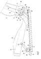
- the motor vehicle rear seat shown in the drawing (hereinafter referred to as "seat") a seat part 1 and a backrest 2 with a Headrest 3, which is guided via rods 4 in the backrest 2 is.
- the seat is not adjustable on the shown vehicle floor arranged.
- a system of two parallel bottom and top rails 6 provided, the lower rails 5 on the vehicle floor are attached and the top rails 6 in the Bottom rails 5 run.
- the backrest 2 is on both sides with their Backrest frame belonging side parts 7 pivotally Adapter 8 struck.
- locking adjusters 9 are provided, that belong to the state of the art and therefore here not explained further. Define the locking adjuster 9 the folding axis 10 of the backrest 2.
- the seat part 1 is in its front area mounted on a rocker 13.
- This rocker 13 supports themselves at one end, forming a lower one Axis of rotation 14 on trestles rising from the top rails 6 15 and is at its other end forming one upper axis of rotation 16 hinged to the seat part 1.
- the seat part 1 has a not shown Steel frame, one in the rear area Pin 17 protrudes laterally. Pass through these bolts 17 one provided in the adjacent adapter 8 Slot 18, which is parallel to the vehicle floor and extends immediately above the top rails 6 with which the adapter 8 are rigidly connected.
- an elongated hole 21 is provided in the side part 7 thereof, which lies on a circular arc around the folding axis 10 and is penetrated by a bolt 22 which leads to a rigid coupling element 23 belongs.
- the length of the elongated hole 21 and the position of the bolt 22 in the slot 21 are dimensioned so that the bolt 22 in the inclination adjustment of the Backrest 2 is not in the normal setting range Ends of the elongated hole 21 strikes, making the possible Tilt adjustment range of the backrest 2 is limited would.
- a pawl 26 is located above the elongated hole 21 mounted on a side part fixed bolt 27, which by a compression spring 28 against an adapter-fixed link 29 is biased. This pawl 26 is under this spring tension with their back on the backdrop 29 on and has a semicircular recess on its front 30 for receiving the bolt 22, as later is explained.
- the coupling element 23 extends into the front area of the seat part 1 and is at this end designed as a rack 24 with a gear 25 Combing which rotatably on the lower axis of rotation 14 of the Swingarm 13 sits.
Landscapes
- Engineering & Computer Science (AREA)
- Aviation & Aerospace Engineering (AREA)
- Transportation (AREA)
- Mechanical Engineering (AREA)
- Seats For Vehicles (AREA)
Description
Die vorliegende Erfindung betrifft einen Kraftfahrzeug Rücksitz mit klappbarer Rückenlehne und absenkbarem Sitzteil, wobei die Rückenlehne zur Schaffung einer Ladefläche auf das Sitzteil klappbar ist.The present invention relates to a motor vehicle rear seat with foldable Backrest and lowerable seat part, the backrest creating a Loading area on the seat part is foldable.
Rücksitze, die - ohne ausgebaut werden zu müssen - die Option bieten, eine zusätzliche sich an den Gepäckraum anschließende Ladefläche zu schaffen, sind aus dem Stand der Technik bekannt. Sie kommen hauptsächlich bei Kleinbussen, Minivans etc. zur Anwendung. Damit die zusätzlich geschaffene Ladefläche im wesentlichen auf dem Niveau des Gepäckraumbodens liegt, ist es erforderlich, daß der Sitz in seiner Ladeposition möglichst flach baut. Diesbezüglich bereitet das gepolsterte Sitzteil des Sitzes Schwierigkeiten, da es dem gewünschten Flachklappen der Rückenlehne im Wege ist.Rear seats which - without having to be removed - offer the option of an additional one to create loading space adjoining the luggage compartment are from the state of the art Technology known. They are mainly used for minibuses, minivans etc. Application. So that the additional loading area created essentially on the Level of the luggage compartment floor, it is necessary that the seat in its Builds the loading position as flat as possible. In this regard, the upholstered seat part of the Seat difficulties as it hinders the desired flat folding of the backrest is.
Zur Lösung dieses Problems gibt es Sitze, bei denen das Sitzteil vor dem Lehnenklappen aus dem Klappbereich entfernbar ist (DE 43 40 446 C2, US-PS 5,730,496). Andere Konstruktionen sehen vor, daß der gesamte Sitz um eine im vorderen Bereich des Sitzteils am Fahrzeugboden angeordnete Querachse nach vorn geschwenkt werden kann (DE-OS 28 49 985, DE 44 22 920 Al). Die vorliegende Erfindung geht im Gegensatz zu den oben skizzierten Lösungen von einem Stand der Technik aus, bei dem das Sitzteil abgesenkt und die Rückenlehne auf das abgesenkte Sitzteil geklappt wird, Derartige Sitze sind aus der US 4,805,953 bekannt. Dieses Dokument wird als nächstliegender Stand der Technik angesehen. Bei dieser Lösung stützt sich das absenkbare Sitzteil in seinem vorderen Bereich auf einer am Fahrzeugboden gelagerten, längs schwenkbaren Schwinge ab, wobei die Vorverlagerung des Sitzteils relativ zur Klappachse der Rückenlehne erfolgt. Aufgabe der Erfindung ist es, einen weiteren Sitz dieser Konzeption zur Verfügung zu stellen.To solve this problem, there are seats in which the seat part in front of the backrest flaps can be removed from the folding area (DE 43 40 446 C2, US Pat. No. 5,730,496). Other Constructions provide that the entire seat by one in the front area of the Seat part arranged on the vehicle floor transverse axis can be pivoted forward (DE-OS 28 49 985, DE 44 22 920 Al). The present invention goes against the solutions outlined above from a prior art, in which the seat part lowered and the backrest is folded onto the lowered seat part, such seats are known from US 4,805,953. This document is considered to be the closest prior art. The lowerable is supported in this solution Seat part in its front area on a longitudinally mounted on the vehicle floor pivotable swing arm, the forward displacement of the seat part relative to Folding axis of the backrest takes place. The object of the invention is to provide another seat to make this concept available.
Gelöst wird diese Aufgabe mit einem Sitz, der die Merkmale des Anspruchs 1 aufweist. This object is achieved with a seat which has the features of
Durch das gleichzeitig mit dem Absenken erfolgende Vorverlagern des Sitzteils relativ zur Lehnen-Klappachse kommt die Vorderseite der Rückenlehne mit ihrem oberen Bereich, in dem sie im Vergleich mit ihrem unteren Bereich relativ dünn baut, auf dem Sitzteil zur Anlage. Dadurch bildet die Rückseite der Rückenlehne eine annähernd ebene Ladefläche. Ohne die Vorverlagerung des Sitzteils käme die Rückenlehne schon vor dem Erreichen der angestrebten ebenen Ladeflächenposition in Anlage mit dem Sitzteil, d.h. die Rückseite der Rückenlehne stünde mehr oder weniger schräg nach vorn und oben.By simultaneously advancing the seat part relative to the lowering The backrest folding axis comes in with its upper area, the front of the backrest which she builds relatively thin compared to her lower area, on the seat part Investment. As a result, the back of the backrest forms an almost flat loading area. Without moving the seat part forward, the backrest would come before it was reached the desired level loading surface position in contact with the seat part, i.e. the The back of the backrest would be more or less sloping forward and upward.
Weitere, vorteilhafte Ausgestaltungen der vorliegenden Erfindung gehen aus den Unteransprüchen hervor.
- Fig. 1
- eine prinzipielle Seitenansicht eines in Gebrauchslage befindlichen Rücksitzes,
- Fig. 2
- einen Ausschnitt A gemäß Fig. 1 in vergrößertem Maßstab,
- Fig. 3
- eine Darstellung gemäß Fig. 2, die den Sitz zu Beginn eines Lehnen-Klappvorganges zeigt, und
- Fig. 4
- eine Seitenansicht des Rücksitzes bei vollständig geklappter Rückenlehne.
- Fig. 1
- a basic side view of a rear seat in the use position,
- Fig. 2
- 2 shows a detail A according to FIG. 1 on an enlarged scale,
- Fig. 3
- 2, showing the seat at the beginning of a backrest folding process, and
- Fig. 4
- a side view of the back seat with the backrest fully folded.
Der in der Zeichnung dargestellte Kraftfahrzeug-Rücksitz
(nachfolgend abkürzend "Sitz" genannt) besitzt
ein Sitzteil 1 sowie eine Rückenlehne 2 mit einer
Kopfstütze 3, die über Stangen 4 in der Rückenlehne 2 geführt
ist. Der Sitz ist längsverschiebbar auf dem nicht
dargestellten Fahrzeugboden angeordnet. Dazu ist, wie üblich,
ein System aus zwei parallelen Unter- 5 und Oberschienen
6 vorgesehen, wobei die Unterschienen 5 am Fahrzeugboden
befestigt sind und die Oberschienen 6 in den
Unterschienen 5 laufen.The motor vehicle rear seat shown in the drawing
(hereinafter referred to as "seat")
a
Die Rückenlehne 2 ist beidseitig mit ihren zum
Lehnenrahmen gehörenden Seitenteilen 7 drehgelenkig an
Adapter 8 angeschlagen. Dazu sind Rastversteller 9 vorgesehen,
die zum Stand der Technik gehören und daher hier
nicht weiter erläutert werden. Die Rastversteller 9 definieren
die Klappachse 10 der Rückenlehne 2.The
Zur Neigungsverstellung der Rückenlehne 2 sind
die Rastversteller 9 zu lösen. Das geschieht mittels eines
an der Seite der Rückenlehne 2 angeordneten, nur symbolisch
dargestellten Hebel 11, der über jeweils einen
Seilzug 12 mit den Rastverstellern 9 verbunden ist. Nach
dem Lösen der Rastversteller 9 kann ein Sitzinsasse durch
Nachgeben bzw. Druck seines Rückens gegen die Rückenlehne
2, die durch nicht dargestellte Federn nach vorn vorgespannt
ist, die Lehnen-Neigung entsprechend seinen Bedürfnissen
einstellen.To adjust the inclination of the
Das Sitzteil 1 ist in seinem vorderen Bereich
auf einer Schwinge 13 gelagert. Diese Schwinge 13 stützt
sich an ihrem einen Ende unter Bildung einer unteren
Drehachse 14 an von den Oberschienen 6 aufragenden Böcken
15 ab und ist an ihrem anderen Ende unter Bildung einer
oberen Drehachse 16 drehgelenkig an das Sitzteil 1 angeschlagen.The
Das Sitzteil 1 besitzt einen nicht dargestellten
Stahlrahmen, von dem im hinteren Bereich jeweils ein
Bolzen 17 seitlich abragt. Diese Bolzen 17 durchgreifen
jeweils ein in dem benachbarten Adapter 8 vorgesehenes
Langloch 18, welches sich parallel zum Fahrzeugboden und
unmittelbar oberhalb der Oberschienen 6 erstreckt, mit
denen die Adapter 8 starr verbunden sind.The
Bei in Gebrauchslage befindlichem Sitz (Fig. 1
und 2) liegen die Bolzen 17 am hinteren Ende der Langlöcher
18 an und werden jeweils von einer Klinke 19 hintergriffen,
die um einen adapterfesten Bolzen 20 schwenkbar
angeordnet ist. Durch diese Arretierung wird verhindert,
daß das Sitzteil 1 sich ungewollt nach vorn verlagern
kann. Durch Betätigung des Hebels 11 können die Klinken
19 über Seilzüge 31 gelöst werden.With the seat in the position of use (Fig. 1
and 2) the
Nachfolgend werden die für die Verlagerung des
Sitzteils 1 erforderlichen Bauteile beschrieben. Diese
können auf beiden Sitzseiten identisch ausgeführt oder
auch nur auf einer Sitzseite vorhanden sein. Nachfolgend
werden diese Bauteile nur für eine Sitzseite erläutert.Below are those for the relocation of the
Unterhalb der Klappachse 10 der Rückenlehne 2
ist in deren Seitenteil 7 ein Langloch 21 vorgesehen,
welches auf einem Kreisbogen um die Klappachse 10 liegt
und von einem Bolzeh 22 durchgriffen wird, der zu einem
starren Koppelelement 23 gehört. Die Länge des Langloches
21 und die Lage des Bolzens 22 im Langloch 21 sind so bemessen,
daß der Bolzen 22 bei der Neigungsverstellung der
Rückenlehne 2 im normalen Einstellbereich nicht an die
Enden des Langloches 21 anschlägt, wodurch der mögliche
Neigungs-Einstellbereich der Rückenlehne 2 beschränkt
wäre.Below the
Oberhalb des Langloches 21 ist eine Klinke 26
an einem seitenteilfesten Bolzen 27 gelagert, die durch
eine Druckfeder 28 gegen eine adapterfeste Kulisse 29
vorgespannt ist. Diese Klinke 26 liegt unter dieser Federspannung
mit ihrer Rückseite an der Kulisse 29 an und
besitzt auf ihrer Vorderseite eine halbkreisförmige Ausnehmung
30 zur Aufnahme des Bolzens 22, wie später noch
erläutert wird.A
Das Koppelelement 23 erstreckt sich bis in den
vorderen Bereich des Sitzteils 1 und ist an diesem Ende
als Zahnstange 24 ausgeführt, die mit einem Zahnrad 25
kämmt, welches drehfest auf der unteren Drehachse 14 der
Schwinge 13 sitzt.The
Nachfolgend wird die Überführung des Sitzes aus
seiner in den Fig. 1 und 2 gezeigten Gebrauchslage in
seine Ladeposition (Fig. 4) beschrieben. Dazu sind zunächst
einmal mittels des Hebels 11, d.h. durch Ziehen
der Seilzüge 12 und 31, die Rastversteller 9 bzw. die das
Sitzteil 1 in seiner Gebrauchslage arretierenden Klinken
19 zu lösen. Die Rückenlehne 2 kann nun aufgrund ihrer
Vorspannung um die Klappachse 10 nach vorn klappen. Durch
diese Bewegung wandert der Bolzen 22 des Koppelelements
23 im Langloch 21 relativ gesehen im Uhrzeigersinn, bis
er am vorderen Ende des Langlochs 21 anliegt. Gleichzeitig
schwenkt auch die lehnenfeste Klinke 26 mit, die bei
dieser Bewegung mit' ihrer Rückseite auf der Kulisse 29
des Adapters 8 entlangläuft und in dem Moment, in dem der
Bolzen 22 an das Ende des Langlochs 21 anschlägt, durch
die nach oben springende Kurvenform der Kulisse 29 mit
ihrer Ausnehmung 30 in Eingriff mit dem Bolzen 22 des
Koppelelements 23 gedrückt wird.Below is the transfer of the seat
its use position shown in Figs. 1 and 2 in
its loading position (Fig. 4) described. To do this first
once by means of the
Durch die Anlage des Bolzens 22 an der Langlochwandung
wird nun das Koppelelement 23 auf dem weiteren
Klappweg der Rückenlehne 2, auf dem auch die Klinke
26 in Eingriff mit dem Bolzen 22 bleibt, mitgenommen,
d.h. nach hinten verschoben. Dadurch wird das Zahnrad 24
und damit die untere Drehachse 14 der Schwinge 13 im Gegenuhrzeigersinn
angetrieben, d.h. die Schwinge 13
schwenkt nach vorn, wodurch das Sitzteil 1 relativ zur
Klappachse 10 nach vorn verlagert und gleichzeitig abgesenkt
wird. Am Schluß des Klappvorganges liegt die in
Fig. 4 gezeigte Situation vor.Through the contact of the
Es ist gut zu erkennen, daß der Bolzen 17 im
Langloch 18 vollständig nach vorn gewandert ist. Dabei
versteht es sich von selbst, daß das Langloch 18 in seiner
Länge so bemessen ist, daß die gewünschte Vorverlagerung
des Sitzteils 1 nicht behindert wird.It can be clearly seen that the
Aus Fig. 4 geht hervor, daß die Rückenlehne 2
natürlich auch hier auf den höchsten Teilen der Sitzteilpolsterung,
den Seitenwangen 32 aufliegt. Aufgrund der
Vorverlagerung des Sitzteils 1 liegt aber der im Vergleich
mit dem unteren Bereich der Rückenlehne 2 relativ
dünn bauende obere Bereich auf den Seitenwangen 32 auf,
wodurch die Rückseite der Rückenlehne 2 eine im wesentlichen
ebene, d.h. zum Fahrzeugboden parallele Ladefläche
33 bildet. Aus der Darstellung gemäß Fig. 4 wird auch
klar, daß bei nicht bzw. nicht so weit vorverlagertem
Sitzteil 1 die Rückenlehne 2 mehr oder weniger schräg
nach vorn und oben stehen würde.4 shows that the
Beim Zurückklappen der Rückenlehne 2 in die Gebrauchslage
wird der Bolzen 22 durch die Klinke 26 mitgenommen,
d.h. das Koppelelement 23 wird vorgeschoben. Dadurch
schwenkt die Schwinge 13, vermittelt durch die
Zahnstange 24 und das Zahnrad 25, um ihre untere Drehachse
14 wieder in ihre Gebrauchslage. Wenn diese erreicht
ist, gibt die Klinke 26 den Bolzen 22 des Koppelelements
23 wieder frei, und die Klinken 19 rasten in die
Bolzen 17 ein, wodurch das Sitzteil 1 in seiner Gebrauchslage
gesichert ist.When the
Claims (5)
- A rear seat of a motor vehicle with a foldable backrest and a lowerable seat part (1), wherein the backrest (2) is capable of being folded onto the seat part (1) in order to provide a loading area and when the backrest (2) is folded forward the seat part is lowered and is displaced forward relative to the folding axis (10) of the backrest (2), wherein the seat part (1) locked in its position of use so as to prevent it from being lowered is supported in its front region on a rocker arm (13) which is mounted directly or indirectly on the vehicle floor and which is capable of being pivoted longitudinally, characterized in that the seat part (1) is guided in its rear region so as to be longitudinally displaceable directly or indirectly on the vehicle floor, wherein the backrest (2) and the rocker arm (13) are connected to each other by a rigid coupling member (23) which is connected at one of its ends below the folding axis (10) of the backrest (2) to the said backrest (2) and is constructed at its other end in the form of a toothed rack (24) which meshes with a toothed wheel (25) mounted in a rotationally fixed manner on the lower axis of rotation (14) of the rocker arm (13), wherein the coupling member (23) transmits the folding movement of the backrest to the rocker arm (13) after the locking of the seat part (1) is released, as a result of which the said rocker arm (13) pivots forward and lowers the seat part (1) and displaces it forward.
- A rear seat of a motor vehicle according to Claim 1, characterized in that the connexion of the coupling member (23) to the backrest (2) is formed by a pin (22) which projects laterally from the coupling member (23) and which engages through an elongate hole (21) situated in the lateral part (7) of the backrest on an arc around the folding axis (10), wherein the length of the elongate hole (21) and the position of the pin (22) in the elongate hole (21) are arranged in such a way that in the region of the inclined setting of the backrest the pin moves without impact in the elongate hole (21), whereas when the backrest (2) is folded forward it strikes against the front end of the elongate hole (21) and pulls the coupling element (23) towards the rear as a result of the folding movement of the backrest.
- A rear seat of a motor vehicle according to Claim 2, characterized in that a catch (26) is articulated in a pivotable manner to the lateral part (7) of the backrest, the said catch (26) engaging in the pin (22) of the coupling member (23) in a forcibly controlled manner as the backrest (2) is folded forward and releasing the pin (22) again only when the seat part (1) has reached its position of use as the backrest (2) is folded back.
- A rear seat of a motor vehicle according to Claim 3, characterized in that the catch (26) runs on a slide block (29) which is provided on the adapter (8) and the outline of which controls the movement pattern of the catch (26) during the folding procedure of the backrest.
- A rear seat of a motor vehicle according to one of the preceding Claims 2 to 4, characterized in that in its rear region the seat part (1) has pins (17) which project laterally on both sides and which are each guided in a respective elongate hole (18) in the adjacent adapter (8) so as to be longitudinally displaceable, wherein at least one of the pins (17) is locked so as to prevent it from being displaced longitudinally when seated in the position of use.
Applications Claiming Priority (2)
| Application Number | Priority Date | Filing Date | Title |
|---|---|---|---|
| DE19841363A DE19841363C1 (en) | 1998-09-10 | 1998-09-10 | Motor vehicle rear seat with foldable backrest and lowerable seat part |
| DE19841363 | 1998-09-10 |
Publications (3)
| Publication Number | Publication Date |
|---|---|
| EP0985575A2 EP0985575A2 (en) | 2000-03-15 |
| EP0985575A3 EP0985575A3 (en) | 2000-05-24 |
| EP0985575B1 true EP0985575B1 (en) | 2004-06-16 |
Family
ID=7880482
Family Applications (1)
| Application Number | Title | Priority Date | Filing Date |
|---|---|---|---|
| EP99117754A Expired - Lifetime EP0985575B1 (en) | 1998-09-10 | 1999-09-09 | Automotive vehicle rear seat with tiltable backrest and lowerable seat part |
Country Status (3)
| Country | Link |
|---|---|
| EP (1) | EP0985575B1 (en) |
| DE (2) | DE19841363C1 (en) |
| ES (1) | ES2218917T3 (en) |
Cited By (2)
| Publication number | Priority date | Publication date | Assignee | Title |
|---|---|---|---|---|
| CN1990303B (en) * | 2005-12-27 | 2010-11-10 | 爱信精机株式会社 | Car seat |
| US10913377B2 (en) | 2016-12-09 | 2021-02-09 | Brose Fahrzeugteile Gmbh & Co. Kommanditgesellschaft, Coburg | Vehicle seat having a locking mechanism for locking a cushion carrier, which can be lowered at least in sections, during an adjustment of a backrest |
Families Citing this family (38)
| Publication number | Priority date | Publication date | Assignee | Title |
|---|---|---|---|---|
| DE19932214B4 (en) * | 1999-07-09 | 2011-12-29 | Lear Corp. | vehicle seat |
| DE10011545C1 (en) * | 2000-03-09 | 2000-11-16 | Faure Bertrand Sitztech Gmbh | Vehicle seat with a folding backrest has an adapter to give a mechanical movement transmission to the locking pawl on folding forwards to release it at the start and lock it when the backrest is folded flat |
| DE10044063A1 (en) * | 2000-08-31 | 2002-03-14 | Volkswagen Ag | Device to alter sitting position of rear seat in motor vehicles has seat frame with rear area moving in two parallel guides and front area turned by pivot link arms |
| DE10047743A1 (en) * | 2000-09-27 | 2002-04-11 | Bayerische Motoren Werke Ag | Folding seat for vehicle has bottom of backrest pivoted to at least one carrier on seat rail |
| DE10055205C2 (en) * | 2000-11-07 | 2003-04-03 | Grammer Ag | Rear seat middle section for a passenger car |
| DE10123776B4 (en) * | 2001-05-16 | 2010-07-01 | GM Global Technology Operations, Inc., Detroit | Vehicle seat with folding kinematics |
| DE10231605B4 (en) * | 2002-07-12 | 2004-09-30 | Daimlerchrysler Ag | Retractable seat |
| EP1558459B1 (en) * | 2002-11-08 | 2009-07-22 | Johnson Controls Technology Company | Thin profile folding vehicle seat |
| ATE416950T1 (en) * | 2003-03-11 | 2008-12-15 | Volkswagen Ag | SEAT ARRANGEMENT FOR A MOTOR VEHICLE AND MOTOR VEHICLE SEAT |
| DE20304713U1 (en) * | 2003-03-17 | 2004-07-29 | Brose Fahrzeugteile Gmbh & Co. Kg, Coburg | Motor vehicle seat, in particular rear seat for a motor vehicle |
| DE10335867B3 (en) * | 2003-08-06 | 2005-02-17 | Keiper Gmbh & Co. Kg | Seat for motor vehicle has control disk able to rotate on the adapter to remove from use position to floor position for carrying load |
| DE10349911A1 (en) * | 2003-10-25 | 2005-06-16 | Dr.Ing.H.C. F. Porsche Ag | vehicle seat |
| DE10350515B3 (en) * | 2003-10-29 | 2005-05-04 | Faurecia Autositze Gmbh & Co. Kg | Seat with a folding backrest for vehicle has coupling member in form of cable with integrated traction spring |
| DE10354065B4 (en) | 2003-11-19 | 2006-05-04 | Johnson Controls Gmbh | Vehicle seat, in particular for a motor vehicle |
| DE10354270B4 (en) * | 2003-11-20 | 2005-09-08 | Keiper Gmbh & Co. Kg | Seat esp. for motor vehicles has seat pad and backrest, which are uncoupled when in folded floor position to execute independent movements for optimum low and flat position |
| DE10354272B4 (en) * | 2003-11-20 | 2005-09-08 | Keiper Gmbh & Co. Kg | Folding mechanism for rear seat of vehicle, comprising two sets of levers and triangular control element |
| DE102004001821B4 (en) * | 2004-01-07 | 2014-02-13 | Volkswagen Ag | Flat folding seat |
| DE102004018637A1 (en) * | 2004-04-16 | 2005-11-10 | Faurecia Autositze Gmbh & Co. Kg | Folding seat for vehicle with linkage to lower seat cushion when seat back is swung into cargo position and incorporating spring a damper inside linkage |
| DE102004021142B4 (en) * | 2004-04-29 | 2009-04-16 | Faurecia Autositze Gmbh | vehicle seat |
| DE102005020335A1 (en) | 2005-02-16 | 2006-08-31 | Dr.Ing.H.C. F. Porsche Ag | Automotive seat |
| DE102005020334A1 (en) * | 2005-04-27 | 2006-11-02 | Sitech Sitztechnik Gmbh | Motor vehicle seat has link, which connects coupling point on backrest to coupling point located below bearing of seat cushion and slidable back and forth along mechanical seat track |
| US7290822B2 (en) | 2005-08-26 | 2007-11-06 | Gm Global Technology Operations, Inc. | Occupant seat system |
| US8096616B2 (en) | 2005-09-15 | 2012-01-17 | Intier Automotive Seating Systems Gmbh | Front row assembly having fold flat mechanism with forward cushion movement |
| DE102005057347C5 (en) * | 2005-12-01 | 2016-09-01 | Faurecia Autositze Gmbh | Automotive seat |
| DE102006016997B4 (en) * | 2006-04-07 | 2019-01-03 | Sitech Sitztechnik Gmbh | Locking and adjusting device for a vehicle seat |
| FR2903940B1 (en) * | 2006-07-20 | 2008-10-10 | Cera | FOLDING MOTOR VEHICLE SEAT COMPRISING A REVERSE STOP. |
| DE102007012429B4 (en) | 2007-03-15 | 2013-08-22 | Faurecia Autositze Gmbh | Automotive seat |
| DE102007020876B4 (en) | 2007-05-04 | 2017-07-06 | Dr. Ing. H.C. F. Porsche Aktiengesellschaft | Folding seat |
| DE102008004120B4 (en) * | 2007-07-13 | 2013-05-23 | Johnson Controls Gmbh | Vehicle seat, in particular rear seat |
| FR2924068B1 (en) * | 2007-11-22 | 2009-12-04 | Faurecia Sieges Automobile | REVERSIBLE SEAT FOR MOTOR VEHICLE |
| DE102008030781B3 (en) * | 2008-06-26 | 2009-11-19 | Keiper Gmbh & Co. Kg | Vehicle seat, particularly motor vehicle seat, has underbody, where cushions and back rest are fixed at underbody in articulated manner |
| DE202008016764U1 (en) | 2008-06-26 | 2009-04-02 | Keiper Gmbh & Co. Kg | Vehicle seat with ground position |
| FR2980412B1 (en) * | 2011-09-22 | 2013-10-25 | Cera | SEAT OF MOTOR VEHICLE |
| DE102013205459B4 (en) | 2013-03-27 | 2017-06-14 | Brose Fahrzeugteile Gmbh & Co. Kg, Coburg | Automotive seat |
| DE102013211495B4 (en) * | 2013-06-19 | 2020-03-12 | Adient Luxembourg Holding S.À R.L. | Vehicle seat, in particular motor vehicle seat |
| CN107972541B (en) | 2016-10-25 | 2022-05-31 | 福特环球技术公司 | Inclination angle adjusting mechanism for vehicle seat and vehicle rear seat |
| US20200156516A1 (en) * | 2018-11-15 | 2020-05-21 | Tachi-S Engineering U.S.A., Incorporated | Sleeper seat for vehicle |
| EP3853062B1 (en) | 2018-12-19 | 2023-11-29 | Magna Seating Inc. | A seat assembly for use in an automotive vehicle for movement between a plurality of positions |
Family Cites Families (7)
| Publication number | Priority date | Publication date | Assignee | Title |
|---|---|---|---|---|
| FR2411105A1 (en) * | 1977-12-09 | 1979-07-06 | Peugeot | ADVANCED TRANSFORMABLE SEAT FOR MOTOR VEHICLES |
| JPH054429Y2 (en) * | 1987-03-30 | 1993-02-03 | ||
| DE4340446C2 (en) * | 1993-11-27 | 1995-11-30 | Daimler Benz Ag | Motor vehicle seat consisting of seat cushion and backrest |
| CA2111725C (en) * | 1993-12-18 | 1998-10-13 | Wojciech Smuk | Combination reclining and folding mechanism for automotive seat assemblies |
| DE4422920A1 (en) * | 1994-06-30 | 1996-01-04 | Opel Adam Ag | Seat arrangement, in particular for the loading or passenger compartment of a motor vehicle |
| DE29512327U1 (en) * | 1995-07-31 | 1995-09-28 | Steyr-Daimler-Puch Ag, Wien | Retractable motor vehicle seat |
| JP3136976B2 (en) * | 1995-12-21 | 2001-02-19 | トヨタ自動車株式会社 | Rear seat device for vehicles |
-
1998
- 1998-09-10 DE DE19841363A patent/DE19841363C1/en not_active Expired - Fee Related
-
1999
- 1999-09-09 ES ES99117754T patent/ES2218917T3/en not_active Expired - Lifetime
- 1999-09-09 EP EP99117754A patent/EP0985575B1/en not_active Expired - Lifetime
- 1999-09-09 DE DE59909732T patent/DE59909732D1/en not_active Expired - Fee Related
Cited By (2)
| Publication number | Priority date | Publication date | Assignee | Title |
|---|---|---|---|---|
| CN1990303B (en) * | 2005-12-27 | 2010-11-10 | 爱信精机株式会社 | Car seat |
| US10913377B2 (en) | 2016-12-09 | 2021-02-09 | Brose Fahrzeugteile Gmbh & Co. Kommanditgesellschaft, Coburg | Vehicle seat having a locking mechanism for locking a cushion carrier, which can be lowered at least in sections, during an adjustment of a backrest |
Also Published As
| Publication number | Publication date |
|---|---|
| EP0985575A3 (en) | 2000-05-24 |
| DE19841363C1 (en) | 2000-04-20 |
| ES2218917T3 (en) | 2004-11-16 |
| DE59909732D1 (en) | 2004-07-22 |
| EP0985575A2 (en) | 2000-03-15 |
Similar Documents
| Publication | Publication Date | Title |
|---|---|---|
| EP0985575B1 (en) | Automotive vehicle rear seat with tiltable backrest and lowerable seat part | |
| DE102011087175B4 (en) | VEHICLE SEAT | |
| DE10130813C2 (en) | Vehicle seat with floor position | |
| DE19932214B4 (en) | vehicle seat | |
| WO2019096774A2 (en) | Easy-entry vehicle seat | |
| DE4003776A1 (en) | VEHICLE SEAT | |
| WO2014075819A1 (en) | Vehicle seat, particularly a motor vehicle seat | |
| EP0211248A2 (en) | Seat adjustment for a motor vehicle | |
| DE2724048A1 (en) | MOTOR VEHICLE SEAT, IN PARTICULAR FOR TWO-WAY MOTOR VEHICLES | |
| DE102008019527B4 (en) | Vehicle seat, in particular motor vehicle seat | |
| EP1329355A1 (en) | Seat module | |
| DE102007036450B3 (en) | Vehicle seat, particularly motor vehicle seat, has moving component, which releases rails releasing device in positive manner during transfer from usage position into non usage position | |
| DE10047743A1 (en) | Folding seat for vehicle has bottom of backrest pivoted to at least one carrier on seat rail | |
| DE68904213T2 (en) | CHILD SAFETY SEAT. | |
| EP0943483A2 (en) | Arrangement of at least two adjacent seats | |
| EP1627768B1 (en) | Collapsible seat particularly for automotive vehicles | |
| DE102020216333B4 (en) | Seating arrangement for a vehicle | |
| DE10353242B3 (en) | Seat for vehicle has first traction device with one end connected to an angle setting release device and other end to longitudinal unlocking mechanism | |
| DE202009006984U1 (en) | Vehicle seat, in particular motor vehicle seat | |
| DE10354272B4 (en) | Folding mechanism for rear seat of vehicle, comprising two sets of levers and triangular control element | |
| DE4211921C2 (en) | Rear seat arrangement for buses | |
| DE2616802A1 (en) | BRACKET FOR PLATFORM ADJUSTABLE VEHICLE SEATS | |
| DE19527750C2 (en) | Vehicle seat | |
| DE4427061C2 (en) | Seat for vehicles | |
| DE102005022984B4 (en) | Vehicle seat, in particular motor vehicle seat |
Legal Events
| Date | Code | Title | Description |
|---|---|---|---|
| PUAI | Public reference made under article 153(3) epc to a published international application that has entered the european phase |
Free format text: ORIGINAL CODE: 0009012 |
|
| AK | Designated contracting states |
Kind code of ref document: A2 Designated state(s): DE ES FR GB IT |
|
| AX | Request for extension of the european patent |
Free format text: AL;LT;LV;MK;RO;SI |
|
| PUAL | Search report despatched |
Free format text: ORIGINAL CODE: 0009013 |
|
| AK | Designated contracting states |
Kind code of ref document: A3 Designated state(s): AT BE CH CY DE DK ES FI FR GB GR IE IT LI LU MC NL PT SE |
|
| AX | Request for extension of the european patent |
Free format text: AL;LT;LV;MK;RO;SI |
|
| RIC1 | Information provided on ipc code assigned before grant |
Free format text: 7B 60N 2/12 A, 7B 60N 2/36 B |
|
| 17P | Request for examination filed |
Effective date: 20000616 |
|
| AKX | Designation fees paid |
Free format text: DE ES FR GB IT |
|
| 17Q | First examination report despatched |
Effective date: 20030514 |
|
| GRAP | Despatch of communication of intention to grant a patent |
Free format text: ORIGINAL CODE: EPIDOSNIGR1 |
|
| GRAS | Grant fee paid |
Free format text: ORIGINAL CODE: EPIDOSNIGR3 |
|
| GRAA | (expected) grant |
Free format text: ORIGINAL CODE: 0009210 |
|
| AK | Designated contracting states |
Kind code of ref document: B1 Designated state(s): DE ES FR GB IT |
|
| REG | Reference to a national code |
Ref country code: GB Ref legal event code: FG4D Free format text: NOT ENGLISH |
|
| REF | Corresponds to: |
Ref document number: 59909732 Country of ref document: DE Date of ref document: 20040722 Kind code of ref document: P |
|
| GBT | Gb: translation of ep patent filed (gb section 77(6)(a)/1977) |
Effective date: 20040712 |
|
| REG | Reference to a national code |
Ref country code: ES Ref legal event code: FG2A Ref document number: 2218917 Country of ref document: ES Kind code of ref document: T3 |
|
| ET | Fr: translation filed | ||
| PLBE | No opposition filed within time limit |
Free format text: ORIGINAL CODE: 0009261 |
|
| STAA | Information on the status of an ep patent application or granted ep patent |
Free format text: STATUS: NO OPPOSITION FILED WITHIN TIME LIMIT |
|
| 26N | No opposition filed |
Effective date: 20050317 |
|
| PGFP | Annual fee paid to national office [announced via postgrant information from national office to epo] |
Ref country code: DE Payment date: 20070921 Year of fee payment: 9 |
|
| PGFP | Annual fee paid to national office [announced via postgrant information from national office to epo] |
Ref country code: ES Payment date: 20070927 Year of fee payment: 9 |
|
| PGFP | Annual fee paid to national office [announced via postgrant information from national office to epo] |
Ref country code: GB Payment date: 20070914 Year of fee payment: 9 |
|
| PGFP | Annual fee paid to national office [announced via postgrant information from national office to epo] |
Ref country code: IT Payment date: 20070921 Year of fee payment: 9 |
|
| PGFP | Annual fee paid to national office [announced via postgrant information from national office to epo] |
Ref country code: FR Payment date: 20080912 Year of fee payment: 10 |
|
| GBPC | Gb: european patent ceased through non-payment of renewal fee |
Effective date: 20080909 |
|
| REG | Reference to a national code |
Ref country code: ES Ref legal event code: PC2A |
|
| REG | Reference to a national code |
Ref country code: FR Ref legal event code: ST Effective date: 20090529 |
|
| PG25 | Lapsed in a contracting state [announced via postgrant information from national office to epo] |
Ref country code: IT Free format text: LAPSE BECAUSE OF NON-PAYMENT OF DUE FEES Effective date: 20080909 Ref country code: DE Free format text: LAPSE BECAUSE OF NON-PAYMENT OF DUE FEES Effective date: 20090401 |
|
| REG | Reference to a national code |
Ref country code: FR Ref legal event code: TQ |
|
| PG25 | Lapsed in a contracting state [announced via postgrant information from national office to epo] |
Ref country code: FR Free format text: LAPSE BECAUSE OF NON-PAYMENT OF DUE FEES Effective date: 20080930 |
|
| REG | Reference to a national code |
Ref country code: ES Ref legal event code: FD2A Effective date: 20080910 |
|
| REG | Reference to a national code |
Ref country code: FR Ref legal event code: CD |
|
| PG25 | Lapsed in a contracting state [announced via postgrant information from national office to epo] |
Ref country code: GB Free format text: LAPSE BECAUSE OF NON-PAYMENT OF DUE FEES Effective date: 20080909 |
|
| PG25 | Lapsed in a contracting state [announced via postgrant information from national office to epo] |
Ref country code: ES Free format text: LAPSE BECAUSE OF NON-PAYMENT OF DUE FEES Effective date: 20080910 |