EP1269025B1 - Compresseur thermocinetique - Google Patents
Compresseur thermocinetique Download PDFInfo
- Publication number
- EP1269025B1 EP1269025B1 EP01907689A EP01907689A EP1269025B1 EP 1269025 B1 EP1269025 B1 EP 1269025B1 EP 01907689 A EP01907689 A EP 01907689A EP 01907689 A EP01907689 A EP 01907689A EP 1269025 B1 EP1269025 B1 EP 1269025B1
- Authority
- EP
- European Patent Office
- Prior art keywords
- nozzle
- gas
- convergent
- divergent
- compressed
- Prior art date
- Legal status (The legal status is an assumption and is not a legal conclusion. Google has not performed a legal analysis and makes no representation as to the accuracy of the status listed.)
- Expired - Lifetime
Links
- 239000007788 liquid Substances 0.000 claims abstract description 34
- 238000001704 evaporation Methods 0.000 claims abstract description 17
- 230000008020 evaporation Effects 0.000 claims abstract description 17
- 230000006835 compression Effects 0.000 claims description 78
- 238000007906 compression Methods 0.000 claims description 78
- 239000007921 spray Substances 0.000 claims description 48
- 210000003739 neck Anatomy 0.000 claims description 39
- 238000001816 cooling Methods 0.000 claims description 35
- 230000007704 transition Effects 0.000 claims description 25
- 238000009434 installation Methods 0.000 claims description 20
- 239000012530 fluid Substances 0.000 claims description 13
- 238000005507 spraying Methods 0.000 claims description 12
- 238000011084 recovery Methods 0.000 claims description 7
- 230000007246 mechanism Effects 0.000 claims description 6
- 230000001914 calming effect Effects 0.000 claims 3
- 239000007789 gas Substances 0.000 description 112
- XLYOFNOQVPJJNP-UHFFFAOYSA-N water Substances O XLYOFNOQVPJJNP-UHFFFAOYSA-N 0.000 description 35
- 235000021183 entrée Nutrition 0.000 description 27
- 229910000975 Carbon steel Inorganic materials 0.000 description 18
- 239000010962 carbon steel Substances 0.000 description 18
- 238000011144 upstream manufacturing Methods 0.000 description 17
- 240000008042 Zea mays Species 0.000 description 15
- 239000010935 stainless steel Substances 0.000 description 13
- 229910001220 stainless steel Inorganic materials 0.000 description 13
- 238000010438 heat treatment Methods 0.000 description 11
- 230000004048 modification Effects 0.000 description 10
- 238000012986 modification Methods 0.000 description 10
- 229910000831 Steel Inorganic materials 0.000 description 9
- 239000000463 material Substances 0.000 description 9
- 239000010959 steel Substances 0.000 description 9
- 241000196324 Embryophyta Species 0.000 description 8
- 238000005299 abrasion Methods 0.000 description 8
- 230000000284 resting effect Effects 0.000 description 8
- 239000000919 ceramic Substances 0.000 description 7
- 230000003247 decreasing effect Effects 0.000 description 7
- 238000013461 design Methods 0.000 description 7
- 239000012809 cooling fluid Substances 0.000 description 6
- 238000004519 manufacturing process Methods 0.000 description 5
- 230000006978 adaptation Effects 0.000 description 4
- 238000002485 combustion reaction Methods 0.000 description 4
- 239000003517 fume Substances 0.000 description 4
- VNWKTOKETHGBQD-UHFFFAOYSA-N methane Chemical compound C VNWKTOKETHGBQD-UHFFFAOYSA-N 0.000 description 4
- 241001080024 Telles Species 0.000 description 3
- 230000008901 benefit Effects 0.000 description 3
- 239000000203 mixture Substances 0.000 description 3
- 230000035939 shock Effects 0.000 description 3
- 230000003584 silencer Effects 0.000 description 3
- 239000007787 solid Substances 0.000 description 3
- 230000009466 transformation Effects 0.000 description 3
- OKTJSMMVPCPJKN-UHFFFAOYSA-N Carbon Chemical compound [C] OKTJSMMVPCPJKN-UHFFFAOYSA-N 0.000 description 2
- 241001415961 Gaviidae Species 0.000 description 2
- 229910052799 carbon Inorganic materials 0.000 description 2
- 238000006243 chemical reaction Methods 0.000 description 2
- 238000009833 condensation Methods 0.000 description 2
- 230000005494 condensation Effects 0.000 description 2
- 238000009826 distribution Methods 0.000 description 2
- 230000000694 effects Effects 0.000 description 2
- 238000012423 maintenance Methods 0.000 description 2
- 239000003345 natural gas Substances 0.000 description 2
- 238000013021 overheating Methods 0.000 description 2
- 230000036961 partial effect Effects 0.000 description 2
- 235000020004 porter Nutrition 0.000 description 2
- 230000002829 reductive effect Effects 0.000 description 2
- 238000003303 reheating Methods 0.000 description 2
- 239000007858 starting material Substances 0.000 description 2
- UGFAIRIUMAVXCW-UHFFFAOYSA-N Carbon monoxide Chemical compound [O+]#[C-] UGFAIRIUMAVXCW-UHFFFAOYSA-N 0.000 description 1
- 238000013459 approach Methods 0.000 description 1
- 238000009835 boiling Methods 0.000 description 1
- 230000008859 change Effects 0.000 description 1
- 230000002860 competitive effect Effects 0.000 description 1
- 230000008602 contraction Effects 0.000 description 1
- 230000001419 dependent effect Effects 0.000 description 1
- 238000000151 deposition Methods 0.000 description 1
- 230000008021 deposition Effects 0.000 description 1
- 238000009792 diffusion process Methods 0.000 description 1
- 238000000605 extraction Methods 0.000 description 1
- 239000003546 flue gas Substances 0.000 description 1
- 239000000446 fuel Substances 0.000 description 1
- 238000002347 injection Methods 0.000 description 1
- 239000007924 injection Substances 0.000 description 1
- 238000000034 method Methods 0.000 description 1
- 238000002156 mixing Methods 0.000 description 1
- 230000007935 neutral effect Effects 0.000 description 1
- 238000005381 potential energy Methods 0.000 description 1
- 230000008569 process Effects 0.000 description 1
- 238000004064 recycling Methods 0.000 description 1
- 230000000717 retained effect Effects 0.000 description 1
- 238000005070 sampling Methods 0.000 description 1
- 229920006395 saturated elastomer Polymers 0.000 description 1
- 238000004513 sizing Methods 0.000 description 1
- 239000000779 smoke Substances 0.000 description 1
- 238000004544 sputter deposition Methods 0.000 description 1
- 239000000725 suspension Substances 0.000 description 1
- 238000012360 testing method Methods 0.000 description 1
- 238000012546 transfer Methods 0.000 description 1
- 238000002604 ultrasonography Methods 0.000 description 1
- 238000009834 vaporization Methods 0.000 description 1
- 230000008016 vaporization Effects 0.000 description 1
- 238000005406 washing Methods 0.000 description 1
Images




Classifications
-
- F—MECHANICAL ENGINEERING; LIGHTING; HEATING; WEAPONS; BLASTING
- F04—POSITIVE - DISPLACEMENT MACHINES FOR LIQUIDS; PUMPS FOR LIQUIDS OR ELASTIC FLUIDS
- F04F—PUMPING OF FLUID BY DIRECT CONTACT OF ANOTHER FLUID OR BY USING INERTIA OF FLUID TO BE PUMPED; SIPHONS
- F04F5/00—Jet pumps, i.e. devices in which flow is induced by pressure drop caused by velocity of another fluid flow
- F04F5/54—Installations characterised by use of jet pumps, e.g. combinations of two or more jet pumps of different type
-
- F—MECHANICAL ENGINEERING; LIGHTING; HEATING; WEAPONS; BLASTING
- F04—POSITIVE - DISPLACEMENT MACHINES FOR LIQUIDS; PUMPS FOR LIQUIDS OR ELASTIC FLUIDS
- F04F—PUMPING OF FLUID BY DIRECT CONTACT OF ANOTHER FLUID OR BY USING INERTIA OF FLUID TO BE PUMPED; SIPHONS
- F04F5/00—Jet pumps, i.e. devices in which flow is induced by pressure drop caused by velocity of another fluid flow
- F04F5/44—Component parts, details, or accessories not provided for in, or of interest apart from, groups F04F5/02 - F04F5/42
- F04F5/46—Arrangements of nozzles
- F04F5/461—Adjustable nozzles
-
- F—MECHANICAL ENGINEERING; LIGHTING; HEATING; WEAPONS; BLASTING
- F04—POSITIVE - DISPLACEMENT MACHINES FOR LIQUIDS; PUMPS FOR LIQUIDS OR ELASTIC FLUIDS
- F04F—PUMPING OF FLUID BY DIRECT CONTACT OF ANOTHER FLUID OR BY USING INERTIA OF FLUID TO BE PUMPED; SIPHONS
- F04F5/00—Jet pumps, i.e. devices in which flow is induced by pressure drop caused by velocity of another fluid flow
- F04F5/44—Component parts, details, or accessories not provided for in, or of interest apart from, groups F04F5/02 - F04F5/42
- F04F5/46—Arrangements of nozzles
- F04F5/462—Arrangements of nozzles with provisions for cooling the fluid
-
- F—MECHANICAL ENGINEERING; LIGHTING; HEATING; WEAPONS; BLASTING
- F04—POSITIVE - DISPLACEMENT MACHINES FOR LIQUIDS; PUMPS FOR LIQUIDS OR ELASTIC FLUIDS
- F04F—PUMPING OF FLUID BY DIRECT CONTACT OF ANOTHER FLUID OR BY USING INERTIA OF FLUID TO BE PUMPED; SIPHONS
- F04F5/00—Jet pumps, i.e. devices in which flow is induced by pressure drop caused by velocity of another fluid flow
- F04F5/44—Component parts, details, or accessories not provided for in, or of interest apart from, groups F04F5/02 - F04F5/42
- F04F5/46—Arrangements of nozzles
- F04F5/465—Arrangements of nozzles with supersonic flow
-
- Y—GENERAL TAGGING OF NEW TECHNOLOGICAL DEVELOPMENTS; GENERAL TAGGING OF CROSS-SECTIONAL TECHNOLOGIES SPANNING OVER SEVERAL SECTIONS OF THE IPC; TECHNICAL SUBJECTS COVERED BY FORMER USPC CROSS-REFERENCE ART COLLECTIONS [XRACs] AND DIGESTS
- Y10—TECHNICAL SUBJECTS COVERED BY FORMER USPC
- Y10S—TECHNICAL SUBJECTS COVERED BY FORMER USPC CROSS-REFERENCE ART COLLECTIONS [XRACs] AND DIGESTS
- Y10S261/00—Gas and liquid contact apparatus
- Y10S261/78—Sonic flow
Definitions
- the present invention relates to an air compressor or other low cost gas whose primary energy used in the compression cycle is not mechanical or electrical energy as in most compressors, but directly from thermal energy; this compressor has no moving parts subjected to wear, and the energy losses due to friction as well as the excess heat of the cold source of the cycle can be recovered to be reused in the compression cycle or to generate steam under pressure which, when mixed with the compressed gas, increases the flow rate.
- This device finds its application in the compression or partial vacuum of any industrial gas, but its thermal cycle is particularly predestined for the realization of high-efficiency thermo-energy plants, the realization of energy saving systems such as mechanical vapor recompression, or the recovery and reconversion of residual thermal energy.
- the compressors consist of devices in which the compression energy of the gas is supplied in the form of mechanical energy: volumetric compressors, centrifugal or axial compressors, ..., or potential energy or kinetics of another driving gas, which is still a form of mechanical energy: ejectors.
- the device according to the invention which uses neither mechanical energy nor drive kinetic energy but only thermal energy to compress the gas, makes it possible to remedy most of these disadvantages by using a different cycle, of pre-treating the gas to be compressed and directly supplying it with thermal energy, to relax the latter at a sonic or supersonic speed through expansion nozzles, to carry out a high-speed and therefore low-speed sampling of heat sputtering temperature and controlled evaporation of liquid distributed in an expansion-cooling nozzle, the nozzle to maintain a high speed, and finally to recompress this gas in an adiabatic compression nozzle to reduce its speed to a normal flow value ;
- the expansion, expansion-cooling and adiabatic compression nozzles may be equipped with a variable geometry system, allowing the sections of their inlet and / or outlet necks to be adjusted in order to regulate, among other things, the flow and the compression ratio of the device
- the low temperature heat removal causes a considerable entropy drop in the gas to be compressed, which results in a
- thermoelectric power plants where it is very advantageously substituted for steam generators in steam plants and especially in combined cycle plants.
- the present invention therefore relates to a device according to the provisions of independent claims 1, 3 and 4.
- the invention also aims at the characteristic points and the embodiments described and claimed in the dependent claims 2 and 5 to 10.
- shock or compression waves that may develop in the supersonic portion of the flow may be suppressed or displaced to the outlet of the device, as described in the detailed alternatives thereafter.
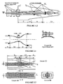
- the device uses a subsonic or sonic flow; it comprises a suction line equipped to pre-treat and heat the gas to be compressed, an optional inlet chamber (C) intended to calm the gas flow before it is admitted into a detent convergent (C1) making it possible to increase its velocity up to the sonic velocity possibly, a transition zone (N), a converging nozzle of Relaxation / Cooling (C2), a cooling system (R) consisting of a set of water spray nozzles (or other liquid) of flow and / or position adjustable from the outside of the device distributed along the zones (N) and (C2) and intended to extract heat from the gas to be compressed by evaporation of the injected liquid, and finally a adiabatic compression divergent (D) for compressing the gas by reducing its speed to a normal flow rate of the order of 10 to 50 m / s before admission to a plenum (T) and its delivery
- the transition zone (N) ensures a continuous connection between the ends of (C1) and (C2) with a generator with monotonous slope, and without angle.
- the suction is equipped with elements for heating the gas to be compressed, such as: Heat exchangers (E1), (E2), ..., (using), directly or using an intermediate fluid, the residual heat contained in the compressed gas at the outlet of the device or any other heat source available elsewhere, Burner (B) supplied with fuel, expansion turbine (TB); these elements are intended to heat the gas to be compressed if its temperature is not high enough at the entrance of the device;
- the suction can be equipped with additional elements such as: Suction filter (F), Silencer (S), Primary compressor (CP) for commissioning the device .
- the discharge pipe may be equipped with elements such as: hot gas recycling systems, heat exchangers (E'1), (E'2), ..., (E'n) for recovering the residual heat contained in the compressed gas of the device, Silencer (S '); this equipment can be powered only by a portion of the compressed gas, and can be installed downstream of a burner and a turbine if the device is intended for mechanical or electrical energy production.
- elements such as: hot gas recycling systems, heat exchangers (E'1), (E'2), ..., (E'n) for recovering the residual heat contained in the compressed gas of the device, Silencer (S '); this equipment can be powered only by a portion of the compressed gas, and can be installed downstream of a burner and a turbine if the device is intended for mechanical or electrical energy production.
- Reheating the gas upstream of (C) allows it to be superheated to keep its temperature from the saturation temperature with the sprayed liquid; depending on the compression ratio and the desired yield, the temperature of overheating can range from 100 ° C to more than 1500 ° C.
- the gas is at each instant expanded and put in speed in the convergent nozzle, and simultaneously cooled by the evaporation of the pulverized liquid, which causes its contraction in regime sonic or subsonic and thus a drop in speed with entropy drop and pressure increase, which attenuates or suppresses the tendency to increase velocity due to the convergent:
- the distribution of the spraying and evaporation along the neutral zone (N) and nozzle (C2) makes it possible to balance the trends of increase and decrease of the speed, and thus to carry out a heat extraction while maintaining an optimal speed sonic or subsonic along the axis of (C2).
- the cooling system (R) makes it possible to adjust the cooling distribution along the axis of (C2) by any means allowing the adjustment of the flow rate and the position of each nozzle;
- an exemplary embodiment, represented on the figure 1.1 shows nozzles arranged in radial fins distributed along the axis of (C2), with the possibility of manually or automatically adjusting from outside the flow of liquid injected into each row of nozzles by means of valves external;
- a second preferred embodiment, represented on the figure 1.2 shows spray nozzles distributed along the axis of the device in the zones (N) and (C2) and disposed at the end of axially sliding concentric tubes; the tubes are supported by threaded bearings at the end of the inlet chamber, the threads making it possible to adjust manually or automatically from the outside the position of each spray nozzle; external valves control the flow of each nozzle.
- the device can be designed with a single spray nozzle, but it then has a degraded performance.
- the retained spray nozzles are preferably high-speed injection nozzles with a minimum droplet size, such as high-pressure nozzles, with assistance with compressed air or steam, and possibly with ultrasounds or microwaves.
- the parts (C), (C1), (N), (C2), (D), and (T) may be made of steel carbon, stainless steel, or any other material compatible with the gas to be compressed and having good mechanical strength and good abrasion resistance at 300 ° C; for gas inlet temperatures of (C) greater than 300 ° C, these parts may for example be made of carbon steel coated internally heat insulating or refractory, carbon steel or stainless steel with jacketed jacket cooled to 1 water or gas to be compressed, ceramic, or any other material with good mechanical resistance and good resistance to abrasion at high temperatures.
- the inlet chamber (C) is made of carbon steel coated internally with refractory concrete, while (C1), (N), (C2), (D), and (T) are made of carbon steel double envelope cooled by circulation of the air to be compressed before entering the air intake; the spray nozzles, installed on-and fed by a system of concentric sliding tubes made of carbon steel with an outside diameter of 60 mm passing through the intake chamber, are distributed in (C2) and make it possible to inject around 4.7 kg / second of water at 200 m / second with average droplet sizes close to 10 ⁇ m.
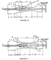
- a variant 2 concerning a sonic or subsonic flow, represented on the figures 2.1, 2.2 , 2.3, and 2.4 , adjusts the gas flow rate to be compressed, the compression ratio, and the energy efficiency of the device.
- the expansion / cooling nozzle (C2) and the adiabatic compression divergent (D) of the basic version 1 are replaced by a convergent nozzle and a divergent nozzle, both with a variable geometry, which makes it possible to adjust the exit section of (C2) and the entry section of (D), and thus the section of the pass between (C2) and (D);
- the variable geometry system, controlled from outside the device is obtained by any mechanism making it possible to modify the passage section of the neck of the device, such as the use of deformable walls on the nozzles (C2) and (D) as presented in the example of the figure 2.1, or the addition of a profiled core (K) or (K1.) axially slidable in the zones (N), (C2), and (D) and fixed on a
- the example of figure 2.1 relates to a nozzle of circular section with deformable walls; the zone (C2) and the zone (D) consist of overlapping flexible steel lamellae arranged regularly on the generatrices of the device, and their ends are welded on the edges of the transition zone (N) and the plenum; clamps circular or any other system such as cylinders, etc .. allow to change the central section of the device, which is then the collar areas (C2) and (D).
- the other elements of the device are identical to those described in the basic version 1.
- the exemplary embodiment shown on the figure 2.1 has the same performance as the previous example for the base case 1, with the possibility of changing the flow rate and the compression ratio of the gas to be compressed.
- the example of figure 2.2 relates to a nozzle of rectangular section; it is equipped with an adjustable system consisting of a core (K) sliding axially in the zones (N), (C2), and (D), and whose axis is fixed on a shaft passing through one or more two ends of the device; the axial position of the core (K) can be adjusted manually or automatically from the outside by a thread arranged on a bearing, by an external jack, or by any other external system.
- an adjustable system consisting of a core (K) sliding axially in the zones (N), (C2), and (D), and whose axis is fixed on a shaft passing through one or more two ends of the device; the axial position of the core (K) can be adjusted manually or automatically from the outside by a thread arranged on a bearing, by an external jack, or by any other external system.
- the spray nozzles are distributed in zones (N) and (C2).
- the core (K) is a rectangular section whose two opposite faces parallel to the axis are juxtaposed to the faces of the nozzle; the other two faces of the core have an aerodynamic profile to minimize the pressure losses of the gas to be compressed; each of them consists of an upstream part (K ') of constant or increasing section in the direction of flow of the gas, a downstream part (K “') of decreasing section in the direction of flow of the gas , and an intermediate part (K ") whose continuous profile, without angle, provides the link between the generatrix of (K ') and that of (K"').
- the core (K) may be made of carbon steel for temperatures below 300 ° C. , made of stainless steel, steel cooled by internal circulation of cooling fluid, ceramic, or any other material having good resistance to abrasion and the temperatures used.
- the example of figure 2.3 relates to a circular section device; it is equipped with an adjustable system consisting of a core (K) sliding axially in the zones (N), (C2), and (D), the core being fixed on a shaft passing through one or both ends of the device; the axial position of the core (K) can be adjusted manually or automatically from the outside by a thread arranged on a bearing, by an external jack, or by any other external system.
- an adjustable system consisting of a core (K) sliding axially in the zones (N), (C2), and (D), the core being fixed on a shaft passing through one or both ends of the device; the axial position of the core (K) can be adjusted manually or automatically from the outside by a thread arranged on a bearing, by an external jack, or by any other external system.
- the spray nozzles are distributed in zones (N) and (C2).
- the core (K) is a piece of solid revolution whose aerodynamic profile minimizes pressure losses of the gas to be compressed; it consists of an upstream part (K ') of constant or increasing section in the direction of flow of the gas, a downstream part (K “') of decreasing section in the direction of gas flow, and an intermediate portion (K ") whose continuous generator (without angle) provides the link between the generator of (K ') and that of (K"').
- the portion (K "') of the core (K) slid in the neck between the expansion / cooling nozzle (C2) and the adiabatic expansion divergence (D).
- the core (K) may be made of carbon steel for temperatures below 300 °, stainless steel, steel cooled by internal circulation of cooling fluid, ceramic, or any other material having good resistance to abrasion and temperatures used.
- the exemplary embodiment shown on the figure 2.3 shows a traversing shaft (K) and supported by a bearing placed in the intake chamber, and by a second bearing at the end of the plenum (T), the latter including a position adjustment thread of the core and the nozzles spray.
- the free space between (K "') and (C2) constitutes a convergent nozzle which performs the same function as the convergent compression nozzle / cooling (C2) described in variant 1, the collar, ie the minimum passage section, of this convergent nozzle is located slightly upstream of the outlet neck of (C2), and its section Ss can be modified at any time from the outside by adjusting the axial position of the core (K).
- This adjustment of the section Ss at the neck, together with a flow rate adjustment of the sprayed liquid, makes it possible to modify the flow rate of the fluid to be compressed, or else to modify the compression ratio and the energy efficiency of the device by modifying the temperature of the device. heating the gas at the inlet of the intake chamber.
- figure 2.4 it also concerns a device of circular section; the principle is identical to that of variant 2.3, but here the core is installed downstream of the device.
- the device is equipped with a core (K1) sliding axially in the areas (N), (C2), (D), and (T), and whose axis is fixed on a shaft passing through one or both ends of the device; the axial position of the core (K1) can be adjusted manually or automatically from the outside by a thread arranged on a bearing, by an external jack, or by any other external system.
- the spray nozzles are distributed in zones (N) and (C2).
- the core (K1) is a piece of solid revolution whose aerodynamic profile minimizes pressure losses of the gas to be compressed; it consists of an upstream part (K'1) of increasing cross-section in the gas flow direction, of a downstream part (K “'1) of constant or decreasing section in the gas flow direction, and an intermediate part (K "1) whose continuous generator, without angle, provides the link between the generatrix of (K'1) and that of (K" '1).
- the portion (K'1) of the core slides in the neck between the expansion / cooling nozzle (C2) and the adiabatic expansion divergence (D).
- the core (K1) may be made of carbon steel for temperatures of less than 300 °, stainless steel, steel cooled by internal circulation of cooling fluid, ceramic, or any other material having good resistance to abrasion and temperatures used.
- the exemplary embodiment shown on the figure 2.4 shows a shaft traversing the core (K1) from one side and resting on bearings placed in the inlet chamber and in the plenum chamber, the latter including a position adjustment thread.
- the free space between (K1) and the duct (C2) constitutes a convergent nozzle which performs the same function as the convergent compression / cooling nozzle (C2). ) described in base version 1; the neck, ie the minimum cross section downstream of this convergent nozzle, is generally located downstream of the outlet neck of (C2), and its section Ss can be modified at any time from the outside by adjusting the axial position of the core (K1).
- This adjustment of the section Ss at the neck, together with a flow rate adjustment of the sprayed liquid, makes it possible to modify the flow rate of the fluid to be compressed, or else to modify the compression ratio and the energy efficiency of the device by modifying the temperature of the device. heating the gas at the inlet of the intake chamber.
- the modifications compared to the basic version 1 concern firstly the use of the expansion convergent (C1) in which the fluid to be compressed is systematically expanded to the sonic speed, and secondly the replacement of the transition zone (N) and the nozzle (C2) via a divergent supersonic expansion nozzle (D1), followed by a transition zone (NT), a convergent compression / cooling nozzle (C3), and a convergent adiabatic compression nozzle (C4); the system of spray nozzles (R), identical to that of the basic version 1, is installed in the zone (C3) and optionally, as described later, in the zones (D1) or (NT).
- the transition zone (NT) ensures a continuous connection between the ends of (D1) and (C3) with a generator with monotonous slope, and without angle.
- the fluid to be compressed is heated upstream of the zone (C) to a temperature that can greatly exceed 1000 to 1500 ° C., and then expanded throughout the zones (C1) and (D1) which constitute a convergent / divergent nozzle of supersonic expansion with sonic velocity at the neck to a pressure Pa a velocity Va and a temperature Ta, and finally compressed with temperature rise in the convergent compression / cooling nozzle (C3) with, simultaneously in the same nozzle (C3), heat removal by evaporation of sprayed liquid; the convergent adiabatic compression nozzle (C4) makes it possible to reduce the fluid to the sonic velocity before subsonic adiabatic compression in the adiabatic compression divergent (D) and its evacuation.
- the spray system consists of a series of nozzles whose positions and / or flow rates can be adjusted manually or automatically from the outside, according to the same concept as in the basic version 1; Evaporative heat removal of the sprayed droplets can be carried out in the zone (D1), the cycle then approaching isobaric cooling, but this case is of little practical interest: we will mention in the following description only the heat taken in the zones (NT) or (C3) with a cycle approximating an isothermal transformation, the spray nozzles being distributed in the zone (C3) and possibly, in advance, in the transition zone (NT ) to account for the lag time between spraying and evaporation.
- the sizing of the device obviously depends first and foremost on the flow rate and the characteristics of the gas to be compressed, as well as on the desired outlet pressure; these criteria being fixed, the choices of the gas reheating temperature upstream of (C), the rate of expansion through (C1) and (C2), and the droplet dimensions, result from a compromise between standard equipment available on the market: types of spray nozzles, materials, etc ..., and between the dimensions and the price of the device, and its energy efficiency.
- the inlet chamber (C) is made of carbon steel coated internally with refractory concrete, while (C1), (D1), (C3), (C4), (D), and (T) are made of steel. carbon double jacket cooled by circulating the air to be compressed before entering the air intake; the ultrasonic spray nozzles, installed and fed by a system of concentric carbon steel sliding tubes of 40 mm outside diameter passing through the intake chamber, are distributed in (C3).
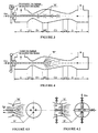
- a variant 4 also concerning a supersonic flow, is represented on the figure 4 ; it follows from variant 3 and makes it possible to simplify the concept by replacing the system of spray nozzles distributed along the axis of the device by a single axial nozzle or by radial nozzles placed at the entrance of the zone (C3) or in the transition zone (NT), the latter provision making it possible to anticipate the time difference between the spraying and the evaporation of the injected liquid; the flow rate and the axial position of these nozzles can be adjusted manually or automatically from the outside of the device.
- the figure 4 represents an exemplary embodiment with a single nozzle located on the axis of the device, at the end of a shaft passing through the intake chamber, and whose flow and position can be adjusted manually or automatically from the outside;
- the figure 4.1 represents another embodiment with several axial nozzles of the same type, and the figure 4.2 represents a third embodiment with adjustable flow nozzles arranged on radial fins.
- the example of figure 4 which is the most practical, will be alone mentioned in the rest of the description.
- the entire flow rate of the sprayed fluid is injected at the beginning of the heat removal cycle, in the zone (NT) or at the inlet of (C3);
- the gas to be compressed is rapidly saturated at the inlet of (C3) by the evaporation of a portion of the droplets, the remainder of the droplets remaining in suspension in the gas stream; as its advance in the compression / cooling nozzle (C3), the gas is compressed with its temperature rise and removal from the previous saturation state, which allows the additional vaporization of droplets;
- this continuous equilibrium makes it possible to extract heat from the gas to be compressed all along the zone (C3) or until the total evaporation of the injected droplets, and this by keeping the gas to be compressed in a state very close to its saturation along the (C3) axis; at each point of this axis, the difference in temperature DT between the actual temperature of the gas and its saturation temperature will balance to its minimum, depending on the droplet size and heat exchange coefficients and gas diffusion; variant 4 thus makes it possible to optimize the thermodynamic cycle of the
- the device represented on the figure 4 has the same elements and has the same performance as the embodiment of variant 3, except for the replacement of the spray nozzle system by a single axial nozzle.
- a variant 5 relating to a supersonic flow, results from variants 3 or 4 and makes it possible to adjust at any time the flow rate of the gas to be compressed, the compression ratio, and the efficiency energy of the device; in this variant, the convergent (C1) and the divergent (D1) variants 3 and 4 are replaced by a convergent nozzle followed by a divergent nozzle both with variable geometries, which allows to adjust the cross section between these two nozzles; the variable geometry system, controlled from outside the device, is obtained by any mechanism for modifying the passage section of the neck between (C1) and (D1) such as those described in the examples below.
- the system with variable geometry is obtained by replacing (C1) and (D1) by a convergent nozzle (CG) with variable geometry, followed by an optional transition zone (NT1) then a divergent nozzle (DG) to variable geometry too, the three walls deformable so as to modify the section of the neck between the two nozzles;
- the deformable wall system may be of the same type as that described in chapter 2.1 and shown on the figure 2.1 for example .
- the nozzle can be equipped with a system of variable geometry also allowing it to be slightly convergent, to facilitate the commissioning of the device under subsonic conditions.
- the transition zone (NT1) provides a continuous connection between the ends of (CG) and (DG) with a generator with monotonous slope, and without angle.
- the speed of the gas to be compressed must be sonic in the first neck of the device and in the second as far as possible, this possibility of modifying its section makes it possible to make the temperature and the flow rate of the gas independent of each other. compress at the outlet of the intake chamber, while respecting the sonic flow constraint in this neck; this makes it possible to modify either the flow rate of the gas to be compressed, or its temperature at the inlet of the first neck, and possibly the flow rate of the liquid sprayed, which causes a modification of the compression ratio of the device and its efficiency - both simultaneously.
- the supersonic diverging expansion nozzle (D1) of variants 3 or 4 is replaced by an adjustable system consisting of an optional transition zone (NT ') followed by a duct (N2) which is slightly divergent, with the addition of a profiled core (K2) sliding axially in the subsonic expansion convergent (C1), in the transition zone (NT '), and in the conduit (N2); the core is fixed on a shaft traversing for example one or both ends of the device; the axial position of the core (K2) can be adjusted manually or automatically from the outside of the device by a thread arranged on a bearing, by an external jack, or by any other system that allows it.
- an adjustable system consisting of an optional transition zone (NT ') followed by a duct (N2) which is slightly divergent, with the addition of a profiled core (K2) sliding axially in the subsonic expansion convergent (C1), in the transition zone (NT '), and in the conduit (N2); the core is fixed on a shaft travers
- the spraying system can be housed in the zone (NT), in the zone (C3), or in the downstream end of (K "'2): see below.
- the core (K2) is a part whose aerodynamic profile minimizes the pressure loss of the gas to be compressed; it consists of an upstream part (K'2) of constant or increasing section in the direction of flow of the gas, a downstream part (K “'2) of decreasing section in the flow direction of the gas, and an intermediate portion (K "2) whose generator continues without angle ensures the connection between the generatrix of (K'2) and that of (K '" 2).
- the part (K "'2) of the core (K2) is housed in the subsonic expansion convergent (C1), in the transition zone (NT'), and in the conduit (N2).
- the core (K2) may be made of carbon steel for temperatures of less than 300.degree. stainless steel, steel cooled by internal circulation of cooling fluid, ceramic, or any other material having good resistance to abrasion and temperatures used.
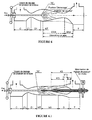
- the exemplary embodiment shown on the figure 5.1 shows a core (K2) supported by a shaft passing axially therethrough, resting itself on a bearing placed in the inlet chamber including a position adjustment thread; in this example, a single spray nozzle is installed at the downstream end of the portion (K "'2) of the core (K2).
- the free space between (K'2) and (C1) constitutes a subsonic expansion convergent nozzle which performs the same function as the convergent nozzle of subsonic expansion (C1) variants 4 or 5, and the free space between (K "'2), (NT'), and (N2) is when it a divergent nozzle supersonic expansion which provides the same role as the nozzle (D1) of variants 3 or 4, the neck, ie the minimum passage section between these two nozzles of the figure 5.1 , is generally located between the maximum section of (K2) and the outlet section of (C1), and its section S's can be modified at any time from the outside by adjusting the axial position of the core (K2).
- the conduit (N2) may be slightly convergent, to facilitate the commissioning of the device under subsonic conditions.
- Variant 6 concerning a supersonic flow, follows from the variants 3 or 4 described above and also makes it possible to modify at any time the compression ratio and / or the efficiency of the device, just like variant 5; it also makes it possible to eliminate or to move towards the output of the device any pressure waves or shock waves which may in certain cases develop in the zones (D1), (NT), or (C3) variants 3 or 4; the principle of this variant is identical to that of variant 5, but the variable geometry concerns the second neck of the device; in this variant, the zones (C3), (C4), and (D) of the variants 3 and 4 are replaced by a variable geometry system controlled from outside the device and making it possible to modify the section of the neck comprised between (C3 ) and D) ; the system of variable geometry is obtained by any mechanism for modifying the section of this neck, such as those described in the examples below.
- the system of variable geometry is obtained by replacing (C3), (C4), and (D) by a nozzle (CG1) with deformable walls that can be set to be preferably slightly divergent when the device is put into service then convergent thereafter, this nozzle then acting as converging nozzle relaxation / cooling (C3) and adiabatic converging nozzle adiabatic (C4);
- (GC1) is followed by a divergent nozzle (DG1) with deformable walls too, the nozzle (DG1) then serves as a divergent adiabatic compression nozzle (D).
- the system of deformable walls can be of the same type as that described in chapter 2.1 and represented on the figure 2.1 for example .
- the first variable geometry nozzle is held in a slightly divergent position, until the compression ratio of the device is high enough that the pressure wave can develop in (D1) has moved in the second divergent nozzle (DG); after this evacuation of the pressure wave, the two variable geometry nozzles can gradually take up their operating position, the pressure wave moving towards the output of the device as the two variable geometry nozzles approach their service position.
- the convergent compression / cooling nozzle (C3) and the convergent adiabatic supersonic compression nozzle (C4) variants 3 or 4 are replaced by a duct (N3) slightly diverging preferably, with an inlet diameter slightly greater than that of (D1) preferably, within which can be slid axially a profiled core (K3) fixed on a shaft traversing for example one or both ends of the device and for adjusting the position of (K3); the position of the core (K3) can be adjusted manually or automatically from the outside of the device by a thread arranged on a bearing, by a jack, or by any other external system allowing it.
- the spray nozzle is housed in the zone (NT) or (N3).
- the divergent duct (D) and optionally the plenum (T) may simply consist of an extension of the slightly divergent duct (N3).
- the core (K3) is a part whose aerodynamic profile minimizes the pressure loss of the gas to be compressed; it consists of an upstream part (K'3) of increasing cross-section in the gas flow direction, of a downstream part (K “'3) of constant or decreasing section in the gas flow direction, and an intermediate part (K "3) whose continuous generator, without angle, provides the link between the generatrix of (K'3) and that of (K" '3).
- the part (K'3) of the core (K3) is housed in the conduit (N3).
- the core (K3) can be made of carbon steel for temperatures of less than 300 °, made of stainless steel , in steel cooled by internal circulation of cooling fluid, ceramic, or any other material having good resistance to abrasion and temperatures used.
- the exemplary embodiment shown on the figure 6.1 shows a shaft traversing the core (K3) from one side and resting on bearings placed in the inlet chamber and in the plenum, the latter including a position adjustment motor; the spray nozzle is placed at the end a sliding tube on the shaft.
- a variant 7, concerning a supersonic flow, results from the simultaneous application of the variants 5 and 6 on the same device, and makes it possible to adjust from the outside independently of each other and at any moment the sections of the two necks. of the device, and thus to modify the flow rate of gas to be compressed, the compression ratio of the device, and its energy efficiency, while also allowing to remove or to move towards its exit any pressure waves or shock waves which may in some cases develop in divergent supersonic variants 3, 4, or 5; in this variant, the zones (C3), (C4), and (D) of the variant 5 are replaced, as for variant 6, by a variable geometry nozzle that can be set to be slightly divergent during the commissioning of the device then convergent thereafter, followed by a divergent nozzle with variable geometry; the diameter of the neck between the two nozzles can be continuously adapted to the diameter of the first neck of the device, that is to say the flow rate and the physical conditions of the gas to be compressed on admission, as well as the physical conditions in output of the device, that is to say the
- the convergent compression / cooling nozzle (C3) and the convergent adiabatic supersonic compression nozzle (C4) of the figure 5.1 are replaced by a duct (N3) preferably slightly divergent, with an inlet diameter slightly greater than that of (D1) preferably, inside which can slide axially a core (K3) whose axis is fixed on a shaft traversing for example one or both ends of the device; the axial position of the core (K3) can be adjusted manually or automatically from the outside of the device by a thread arranged on a bearing, by an external jack, or by any other external system allowing it.
- the zones (N2), (NT), (N3), (D) and (T) can be grouped into a single duct of slightly divergent section.
- the core (K3) is a piece of solid revolution whose aerodynamic profile minimizes pressure losses of the gas to be compressed; it consists of an upstream part (K'3) of increasing cross-section in the gas flow direction, of a downstream part (K “'3) of constant or decreasing section in the gas flow direction, and an intermediate part (K "3) whose continuous generator, without angle, provides the link between the generatrix of (K'3) and that of (K '" 3).
- the part (K'3) of the core (K3) is housed in the conduit (N3).
- the spray nozzle is housed in one of the zones (N2), (NT), or (N3), between (K “'2), downstream end of (K2), and (K'3), upstream end of (K3).
- the core (K3) can be made of carbon steel for temperatures of less than 300 °, made of stainless steel , in steel cooled by internal circulation of cooling fluid, ceramic, or any other material having good resistance to abrasion and temperatures used.
- the exemplary embodiment shown on the figure 7.1 shows a shaft passing right through the core (K2) and the core (K3), and resting on bearings placed in the combustion chamber and in the plenum; each bearing includes a motor for adjusting the axial position of each of the cores, and the spray nozzle is installed directly on the downstream end of (K "'2).
- the free space between (K2), (C1), (NT '), and (N2) comprises a first neck section S's adjustable from the outside by adjusting the axial position of the core (K2).
- the free space between (K3), (N3), and (D) comprises a second neck section Ss adjustable from the outside by adjusting the axial position of the core (K3).
- a variant 8 concerning the spray nozzles of the basic option 1 or variants 2 to 7 described above, is represented on the figure 8 ; it consists in using as a spray assist fluid a portion of the compressed gas generated by the device, or steam generated by heat recovery on the compressed gas downstream of the plenum.
- This variant makes it possible to reduce the size of the droplets of sprayed liquid and to increase their initial speed without any additional supply of external mechanical energy, and thus to improve the energy efficiency of the device.
- figure 8 the same type of installation as that of the figure 7.1 but it is equipped with assistance with spraying from compressed air taken out of the device.
- T plenum
- any other heat source internal to the device such as heat recovered in the double envelopes, or heat external to the device, may be used .
- figure 9 the same type of installation as that of the figure 8 , in which the liquid to be sprayed is first heated in a heat exchanger installed on the line of evacuation of the compressed gas.
- a device according to the figure 9 having the same dimensions and the same performance as the embodiment of variant 8, with an addition temperature of the compressed air increased by 20 ° C, can be obtained by adding on the discharge line a heat exchanger thermal (E'1) for preheating at 40 ° C the spray water.
- E'1 heat exchanger thermal
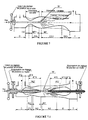
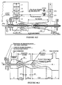
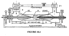
- a variant 10 relates to the parallel or series installation of several of the devices described in the basic option 1 and the variants 2 to 9 in order to facilitate its implementation, to achieve compression rates that can not be achieved. by a single device, to improve the overall efficiency of the installation, or to facilitate the commissioning of the installation; the devices can be distinct from each other as in the example of the figure 10 described below, or nested one inside the other as in the example of the figure 10.1 two devices installed in parallel in the same envelope, or as in the examples of the Figures 10.2, 10.3 , and 10.4 wherein two devices according to claims 2 and 9 are installed in series and nested within each other with suction line, inlet chamber (C), convergent (C1) and (C2), and inlet core common core (K) for the first subsonic and core device (K2) for the second supersonic device.
- C suction line
- C inlet chamber
- C1 and C2 convergent
- K inlet core common core
- figure 10 allows the commissioning of a supersonic compression air compressor with a high compression ratio, using a low-performance starter compressor. It consists of two separate devices installed in series: a first sonic device according to the figure 2 . 3 with upstream core for adjusting air flow and whose suction line includes a filter, a silencer, a compressor, and an oil burner, followed by a supersonic downstream device according to the figure 9 with upstream and downstream cores whose suction line includes an exchanger for heating the air with a thermal fluid; the discharge line of the downstream device includes a recovery exchanger for heating the thermal fluid followed by a second heat exchanger for heating the spray water.
- the first upstream device is used only during the commissioning of the installation, to ensure sufficient overpressure to allow the start of the second device, after which the first is stopped.
- the second downstream device used in normal operation and therefore having to be efficient, includes in addition a heat recovery device for heating the air at the intake, a second recuperator for heating the spray water, and an assistance for spraying by using compressed air taken out of the installation.
- figure 10.1 allows the realization of a compressor of very large capacity by the parallel use of two devices identical to that shown on the figure 8 ; the two devices installed in parallel are nested one inside the other, the cores of each of them being installed in a common envelope; this arrangement reduces the size of the cores, which would become too large on a single device of very large capacity.
- figure 10.2 is a simplified version of the example of the figure 10 in which the two devices are nested; it consists of a supersonic device according to the figure 9 in which the ducts (N2), (NT), (N3), and (D) are grouped together in a single, slightly divergent duct, and in which the zone (C1) can act as the zones (C1) and (C2) of the sonic device shown on the figure 2.3 ; the kernel (K2) of the supersonic device has spray nozzles distributed along its axis, and may act as the nucleus (K1) of the sonic device shown in FIG. figure 2.3 .
- the core (K3) is completely removed in the plenum (T); the compressor, the burner, and the nucleus spray nozzles (K1) are put into operation, and the upstream part of the device is used alone, as a sonic installation; when the pressure downstream of (C2) is sufficiently high, the compressor is stopped, the supersonic part of the device is also put into operation and, when the pressure in the plenum is sufficiently high, the spraying nozzles of the core (K1), ie those of the sonic device, are stopped gradually; the entire installation then functions as a single supersonic device, and the flow rate, compression ratio, and plant efficiency settings can be made by adjusting the burner, the flow rate of the liquid sprayed, and the positions of ( K2) and (K3).
- figure 10.3 is also a simplified version of a sonic device embedded in a supersonic device to facilitate commissioning; it consists of a supersonic device according to the figure 7 with variable-geometry nozzles by deformable walls in which the convergent (CG) of the supersonic device can play the role of the convergents (C1) and (C2) of the sonic device represented on the figure 2.3 ; the convergent (CG) of the supersonic device comprises in addition spray nozzles (R) distributed along its axis, which play the same role as the spray nozzles distributed in the zone (C2) of the sonic device.
- CG convergent
- R spray nozzles
- the duct (CG1) When the installation is put into service, the duct (CG1) is placed in the starting position, slightly diverging; the compressor, the burner, and the nozzles of the sonic device are put into operation, and the upstream part of the device is used alone, as a sonic installation; when the pressure downstream of (C2) is sufficiently high, the compressor is stopped, the downstream supersonic part of the device is also put into operation and, when the pressure in the plenum chamber is sufficiently high, the spray nozzles of the device sonic are also gradually stopped; the entire installation then functions as a single supersonic device, and the flow rate, compression ratio, and efficiency settings of the installation can be made by adjusting the burner, the flow rate of the sprayed liquid, and the sections of each. of the two necks of the device.
- figure 10.4 allows, in a very simplified way, to obtain the same result as the examples of figures 10 and 10.2 that is, it allows the commissioning of a supersonic air compression device with a high compression ratio, using a low-performance starter compressor; it consists of a supersonic device according to the figure 8 and a sonic device according to the figure 2.4 installed in series and nested in one another.
- the ducts (NT '), (N2), (NT), and (N3) are grouped into a single, slightly convergent duct, and the core (K3) and the spray nozzle (R) of the supersonic device are also used as a core (K1) and as a nozzle (R) of the sonic device when the latter is used.
- the sonic device is used alone, the core (K2), then being entirely withdrawn in (C), until a pressure gain is obtained which is sufficient to allow the setting in use of the supersonic device, ie to allow the introduction of (K2) in (C1) to create a divergent).
Landscapes
- Engineering & Computer Science (AREA)
- Physics & Mathematics (AREA)
- Fluid Mechanics (AREA)
- Mechanical Engineering (AREA)
- General Engineering & Computer Science (AREA)
- Nozzles (AREA)
- Structures Of Non-Positive Displacement Pumps (AREA)
- Jet Pumps And Other Pumps (AREA)
- Compressors, Vaccum Pumps And Other Relevant Systems (AREA)
- Sorption Type Refrigeration Machines (AREA)
- Compressor (AREA)
Applications Claiming Priority (3)
| Application Number | Priority Date | Filing Date | Title |
|---|---|---|---|
| FR0001881A FR2805008B1 (fr) | 2000-02-16 | 2000-02-16 | Compresseur termocinetique |
| FR0001881 | 2000-02-16 | ||
| PCT/FR2001/000230 WO2001061196A1 (fr) | 2000-02-16 | 2001-01-25 | Compresseur thermocinetique |
Publications (2)
| Publication Number | Publication Date |
|---|---|
| EP1269025A1 EP1269025A1 (fr) | 2003-01-02 |
| EP1269025B1 true EP1269025B1 (fr) | 2008-03-19 |
Family
ID=8847033
Family Applications (1)
| Application Number | Title | Priority Date | Filing Date |
|---|---|---|---|
| EP01907689A Expired - Lifetime EP1269025B1 (fr) | 2000-02-16 | 2001-01-25 | Compresseur thermocinetique |
Country Status (12)
| Country | Link |
|---|---|
| US (1) | US6935096B2 (da) |
| EP (1) | EP1269025B1 (da) |
| AT (1) | ATE389811T1 (da) |
| AU (1) | AU2001235598A1 (da) |
| CA (1) | CA2399580C (da) |
| DE (1) | DE60133268T2 (da) |
| DK (1) | DK1269025T3 (da) |
| ES (1) | ES2303524T3 (da) |
| FR (1) | FR2805008B1 (da) |
| PT (1) | PT1269025E (da) |
| RU (1) | RU2286483C2 (da) |
| WO (1) | WO2001061196A1 (da) |
Cited By (1)
| Publication number | Priority date | Publication date | Assignee | Title |
|---|---|---|---|---|
| FR2981981A1 (fr) * | 2011-10-28 | 2013-05-03 | Helios Energy Partners | Procede de conversion en energie mecanique d'une energie thermique, dispositif faisant application, et dispositif particulierement adapte a la mise en oeuvre dudit procede |
Families Citing this family (41)
| Publication number | Priority date | Publication date | Assignee | Title |
|---|---|---|---|---|
| GB9106317D0 (en) * | 1991-03-25 | 1991-05-08 | Nat Res Dev | Material having a passage therethrough |
| US8788829B2 (en) | 2006-08-17 | 2014-07-22 | Aol Inc. | System and method for interapplication communications |
| JP2009002845A (ja) * | 2007-06-22 | 2009-01-08 | Micronics Japan Co Ltd | 接触子及び接続装置 |
| FR2919717A1 (fr) * | 2007-11-06 | 2009-02-06 | Air Liquide | Procede et appareil de separation d'air avec compression de produit |
| FR2924109B1 (fr) * | 2007-11-26 | 2010-11-26 | Air Liquide | Procede et installation de production d'un gaz de synthese refroidi et comprime |
| FR2919920A1 (fr) * | 2007-12-14 | 2009-02-13 | Air Liquide | Procede et appareil de separation d'air par distillation cryogenique |
| FR2927407B1 (fr) * | 2008-02-07 | 2010-05-07 | Air Liquide | Procede et appareil de separation des gaz de l'air. |
| WO2009108079A2 (en) * | 2008-02-22 | 2009-09-03 | Siemens Aktiengesellschaft | Method and plant for generating mechanical or electrical power from waste heat and apparatus for a power plant |
| WO2009116889A1 (en) * | 2008-03-19 | 2009-09-24 | Siemens Aktiengesellschaft | Apparatus for use in a plant for generating electrical or mechanical power from waste heat and use of such an apparatus |
| US8225606B2 (en) | 2008-04-09 | 2012-07-24 | Sustainx, Inc. | Systems and methods for energy storage and recovery using rapid isothermal gas expansion and compression |
| US8479505B2 (en) | 2008-04-09 | 2013-07-09 | Sustainx, Inc. | Systems and methods for reducing dead volume in compressed-gas energy storage systems |
| US7958731B2 (en) | 2009-01-20 | 2011-06-14 | Sustainx, Inc. | Systems and methods for combined thermal and compressed gas energy conversion systems |
| US8037678B2 (en) | 2009-09-11 | 2011-10-18 | Sustainx, Inc. | Energy storage and generation systems and methods using coupled cylinder assemblies |
| US8677744B2 (en) | 2008-04-09 | 2014-03-25 | SustaioX, Inc. | Fluid circulation in energy storage and recovery systems |
| US7802426B2 (en) | 2008-06-09 | 2010-09-28 | Sustainx, Inc. | System and method for rapid isothermal gas expansion and compression for energy storage |
| US20100307156A1 (en) | 2009-06-04 | 2010-12-09 | Bollinger Benjamin R | Systems and Methods for Improving Drivetrain Efficiency for Compressed Gas Energy Storage and Recovery Systems |
| US8448433B2 (en) | 2008-04-09 | 2013-05-28 | Sustainx, Inc. | Systems and methods for energy storage and recovery using gas expansion and compression |
| US8240140B2 (en) | 2008-04-09 | 2012-08-14 | Sustainx, Inc. | High-efficiency energy-conversion based on fluid expansion and compression |
| WO2009126784A2 (en) | 2008-04-09 | 2009-10-15 | Sustainx, Inc. | Systems and methods for energy storage and recovery using compressed gas |
| US8250863B2 (en) | 2008-04-09 | 2012-08-28 | Sustainx, Inc. | Heat exchange with compressed gas in energy-storage systems |
| US8359856B2 (en) | 2008-04-09 | 2013-01-29 | Sustainx Inc. | Systems and methods for efficient pumping of high-pressure fluids for energy storage and recovery |
| US8474255B2 (en) | 2008-04-09 | 2013-07-02 | Sustainx, Inc. | Forming liquid sprays in compressed-gas energy storage systems for effective heat exchange |
| FR2934993A1 (fr) * | 2008-08-12 | 2010-02-19 | Air Liquide | Valorisation de la chaleur des fumees d'un four a verre a l'aide d'un compresseur thermocinetique |
| US7963110B2 (en) | 2009-03-12 | 2011-06-21 | Sustainx, Inc. | Systems and methods for improving drivetrain efficiency for compressed gas energy storage |
| FR2943657A1 (fr) * | 2009-03-25 | 2010-10-01 | Air Liquide | Procede et installation de production d'hydrogene refroidi et comprime |
| FR2943656A1 (fr) * | 2009-03-25 | 2010-10-01 | Air Liquide | Procede et installation de production d'hydrogene mettant en oeuvre un compresseur thermocinetique |
| US8104274B2 (en) | 2009-06-04 | 2012-01-31 | Sustainx, Inc. | Increased power in compressed-gas energy storage and recovery |
| WO2011056855A1 (en) | 2009-11-03 | 2011-05-12 | Sustainx, Inc. | Systems and methods for compressed-gas energy storage using coupled cylinder assemblies |
| US8191362B2 (en) | 2010-04-08 | 2012-06-05 | Sustainx, Inc. | Systems and methods for reducing dead volume in compressed-gas energy storage systems |
| US8171728B2 (en) | 2010-04-08 | 2012-05-08 | Sustainx, Inc. | High-efficiency liquid heat exchange in compressed-gas energy storage systems |
| US8234863B2 (en) | 2010-05-14 | 2012-08-07 | Sustainx, Inc. | Forming liquid sprays in compressed-gas energy storage systems for effective heat exchange |
| US8495872B2 (en) | 2010-08-20 | 2013-07-30 | Sustainx, Inc. | Energy storage and recovery utilizing low-pressure thermal conditioning for heat exchange with high-pressure gas |
| US8453997B2 (en) * | 2010-11-20 | 2013-06-04 | Fisonic Holding Limited | Supersonic nozzle |
| US8578708B2 (en) | 2010-11-30 | 2013-11-12 | Sustainx, Inc. | Fluid-flow control in energy storage and recovery systems |
| RU2455532C1 (ru) * | 2011-01-20 | 2012-07-10 | Виталий Васильевич Сальков | Разгонное устройство |
| EP2715075A2 (en) | 2011-05-17 | 2014-04-09 | Sustainx, Inc. | Systems and methods for efficient two-phase heat transfer in compressed-air energy storage systems |
| US20130091834A1 (en) | 2011-10-14 | 2013-04-18 | Sustainx, Inc. | Dead-volume management in compressed-gas energy storage and recovery systems |
| RU2468260C1 (ru) * | 2012-01-24 | 2012-11-27 | Владимир Леонидович Письменный | Способ повышения давления газа |
| US9686903B2 (en) * | 2014-06-17 | 2017-06-27 | Cnh Industrial Canada, Ltd. | Optimizing product flow in a drop chute by controlling the shape and position of vortices present in the system |
| US11292056B2 (en) * | 2018-07-06 | 2022-04-05 | Divergent Technologies, Inc. | Cold-spray nozzle |
| RO133288A0 (ro) * | 2018-09-26 | 2019-04-30 | Dumitru Oncescu | Procedeu şi instalaţie - pompă energetică, de joasă temperatură - motosinteză |
Family Cites Families (15)
| Publication number | Priority date | Publication date | Assignee | Title |
|---|---|---|---|---|
| BE537693A (da) * | ||||
| US891901A (en) * | 1905-08-04 | 1908-06-30 | Max Blieden | Internal-combustion engine. |
| US1134365A (en) * | 1913-12-01 | 1915-04-06 | Llewellyn T Barnes | Carbureter. |
| US2926493A (en) * | 1955-03-07 | 1960-03-01 | Babcock & Wilcox Co | Gas turbine with waste heat steam generator |
| GB928661A (en) * | 1960-10-28 | 1963-06-12 | Rolls Royce | Improvements in or relating to pumps |
| US3369361A (en) * | 1966-03-07 | 1968-02-20 | Gale M. Craig | Gas turbine power plant with sub-atmospheric spray-cooled turbine discharge into exhaust compressor |
| US3915222A (en) * | 1969-05-19 | 1975-10-28 | Francis R Hull | Compressible fluid contact heat exchanger |
| US3782116A (en) * | 1971-03-10 | 1974-01-01 | Trw Inc | Foam cooling and acoustic damping for internal combustion engines |
| FR2359626A2 (fr) * | 1976-07-28 | 1978-02-24 | Sacilor | Procede et dispositif d'epuration de gaz ou de fumees poussiereuses |
| FR2377836A1 (fr) * | 1977-01-25 | 1978-08-18 | Rhone Poulenc Ind | Procede et dispositif pour la mise en contact de produits sous forme de plusieurs phases et separation des produits du melange et application |
| US4272499A (en) * | 1979-11-28 | 1981-06-09 | Lone Star Steel Company | Process and apparatus for the removal of particulate matter and reactive or water soluble gases from carrier gases |
| US4867918A (en) * | 1987-12-30 | 1989-09-19 | Union Carbide Corporation | Gas dispersion process and system |
| DE69221935T2 (de) * | 1991-05-22 | 1998-04-09 | Toshiba Kawasaki Kk | Dampfinjektorsystem |
| RU2084707C1 (ru) * | 1995-02-14 | 1997-07-20 | Валерий Григорьевич Цегельский | Насосно-эжекторная установка |
| RU2130132C1 (ru) * | 1997-06-16 | 1999-05-10 | Акционерное общество открытого типа "Оренбургнефть" | Струйная компрессорная установка |
-
2000
- 2000-02-16 FR FR0001881A patent/FR2805008B1/fr not_active Expired - Fee Related
-
2001
- 2001-01-25 US US10/203,961 patent/US6935096B2/en not_active Expired - Fee Related
- 2001-01-25 WO PCT/FR2001/000230 patent/WO2001061196A1/fr not_active Ceased
- 2001-01-25 AU AU2001235598A patent/AU2001235598A1/en not_active Abandoned
- 2001-01-25 PT PT01907689T patent/PT1269025E/pt unknown
- 2001-01-25 ES ES01907689T patent/ES2303524T3/es not_active Expired - Lifetime
- 2001-01-25 CA CA002399580A patent/CA2399580C/fr not_active Expired - Fee Related
- 2001-01-25 DK DK01907689T patent/DK1269025T3/da active
- 2001-01-25 RU RU2002124608/06A patent/RU2286483C2/ru not_active IP Right Cessation
- 2001-01-25 EP EP01907689A patent/EP1269025B1/fr not_active Expired - Lifetime
- 2001-01-25 AT AT01907689T patent/ATE389811T1/de active
- 2001-01-25 DE DE60133268T patent/DE60133268T2/de not_active Expired - Lifetime
Cited By (1)
| Publication number | Priority date | Publication date | Assignee | Title |
|---|---|---|---|---|
| FR2981981A1 (fr) * | 2011-10-28 | 2013-05-03 | Helios Energy Partners | Procede de conversion en energie mecanique d'une energie thermique, dispositif faisant application, et dispositif particulierement adapte a la mise en oeuvre dudit procede |
Also Published As
| Publication number | Publication date |
|---|---|
| DE60133268D1 (de) | 2008-04-30 |
| ES2303524T3 (es) | 2008-08-16 |
| US20030012658A1 (en) | 2003-01-16 |
| PT1269025E (pt) | 2008-07-10 |
| FR2805008B1 (fr) | 2002-05-31 |
| DK1269025T3 (da) | 2008-06-30 |
| DE60133268T2 (de) | 2009-04-23 |
| RU2286483C2 (ru) | 2006-10-27 |
| AU2001235598A1 (en) | 2001-08-27 |
| CA2399580A1 (fr) | 2001-08-23 |
| WO2001061196A1 (fr) | 2001-08-23 |
| US6935096B2 (en) | 2005-08-30 |
| CA2399580C (fr) | 2008-04-22 |
| FR2805008A1 (fr) | 2001-08-17 |
| ATE389811T1 (de) | 2008-04-15 |
| EP1269025A1 (fr) | 2003-01-02 |
Similar Documents
| Publication | Publication Date | Title |
|---|---|---|
| CA2399580C (fr) | Compresseur thermocinetique | |
| EP2795073B1 (fr) | Procédé et installation de cogénération | |
| FR2478736A1 (fr) | Procede et systeme de generation de puissance par moteur a combustion interne suralimente | |
| FR2899936A1 (fr) | Procede de rechauffage selectif d'air a l'entree d'un compresseur associe a une turbine a gaz et systeme de production d'electricite. | |
| CN104603423B (zh) | 用于产生电能的系统和方法 | |
| CN105980690A (zh) | 用于产生电能的系统和方法 | |
| EA015075B1 (ru) | Вращающееся устройство для создания давления | |
| FR2583988A1 (fr) | Procede de distillation avec recuperation d'energie par recompression de vapeur a l'aide d'un ejecteur | |
| FR2787560A1 (fr) | Procede de separation cryogenique des gaz de l'air | |
| JP2019508631A (ja) | 燃焼チャンバ装置および燃焼チャンバ装置を含むシステム | |
| EP3814611B1 (fr) | Procédé et dispositif de conversion d'énergie thermique | |
| US11898469B2 (en) | Reaction turbine operating on condensing vapors | |
| EP3698049B1 (fr) | Dispositif et procédé de compression | |
| EP0629828B1 (fr) | Procédé et installation de production d'oxygène et/ou d'azote sous pression à débit variable | |
| EP1359309B1 (fr) | Turbine à gaz comportant un dispositif de mélange de gaz à lobes et à tubes | |
| FR2981981A1 (fr) | Procede de conversion en energie mecanique d'une energie thermique, dispositif faisant application, et dispositif particulierement adapte a la mise en oeuvre dudit procede | |
| FR2570436A1 (fr) | Turbine a detente de liquide chaud pressurise et dispositifs comportant une telle turbine | |
| BE515273A (da) | ||
| EP4463662A1 (fr) | Dispositif et procédé de réchauffement puis détente d'un gaz | |
| BE487485A (da) | ||
| FR2944095A1 (fr) | Procede de liquefaction de gaz naturel utilisant des turbines a gaz a basse temperature d'echappement | |
| BE473618A (da) | ||
| CH312372A (fr) | Installation à turbine à gaz. | |
| BE382171A (da) | ||
| FR3036736A1 (fr) | Turbomachine d’aeronef |
Legal Events
| Date | Code | Title | Description |
|---|---|---|---|
| PUAI | Public reference made under article 153(3) epc to a published international application that has entered the european phase |
Free format text: ORIGINAL CODE: 0009012 |
|
| 17P | Request for examination filed |
Effective date: 20020916 |
|
| AK | Designated contracting states |
Kind code of ref document: A1 Designated state(s): AT BE CH CY DE DK ES FI FR GB GR IE IT LI LU MC NL PT SE TR |
|
| AX | Request for extension of the european patent |
Free format text: AL;LT;LV;MK;RO;SI |
|
| 17Q | First examination report despatched |
Effective date: 20060828 |
|
| GRAP | Despatch of communication of intention to grant a patent |
Free format text: ORIGINAL CODE: EPIDOSNIGR1 |
|
| GRAS | Grant fee paid |
Free format text: ORIGINAL CODE: EPIDOSNIGR3 |
|
| GRAA | (expected) grant |
Free format text: ORIGINAL CODE: 0009210 |
|
| AK | Designated contracting states |
Kind code of ref document: B1 Designated state(s): AT BE CH CY DE DK ES FI FR GB GR IE IT LI LU MC NL PT SE TR |
|
| REG | Reference to a national code |
Ref country code: GB Ref legal event code: FG4D Free format text: NOT ENGLISH |
|
| REG | Reference to a national code |
Ref country code: CH Ref legal event code: EP |
|
| RAP2 | Party data changed (patent owner data changed or rights of a patent transferred) |
Owner name: THERMOKIN |
|
| RIN2 | Information on inventor provided after grant (corrected) |
Inventor name: THERMOKIN |
|
| REF | Corresponds to: |
Ref document number: 60133268 Country of ref document: DE Date of ref document: 20080430 Kind code of ref document: P |
|
| REG | Reference to a national code |
Ref country code: IE Ref legal event code: FG4D Free format text: LANGUAGE OF EP DOCUMENT: FRENCH |
|
| NLT2 | Nl: modifications (of names), taken from the european patent patent bulletin |
Owner name: THERMOKIN Effective date: 20080416 |
|
| REG | Reference to a national code |
Ref country code: DK Ref legal event code: T3 |
|
| REG | Reference to a national code |
Ref country code: SE Ref legal event code: TRGR |
|
| REG | Reference to a national code |
Ref country code: PT Ref legal event code: SC4A Free format text: AVAILABILITY OF NATIONAL TRANSLATION Effective date: 20080527 |
|
| REG | Reference to a national code |
Ref country code: ES Ref legal event code: FG2A Ref document number: 2303524 Country of ref document: ES Kind code of ref document: T3 |
|
| PLBE | No opposition filed within time limit |
Free format text: ORIGINAL CODE: 0009261 |
|
| STAA | Information on the status of an ep patent application or granted ep patent |
Free format text: STATUS: NO OPPOSITION FILED WITHIN TIME LIMIT |
|
| 26N | No opposition filed |
Effective date: 20081222 |
|
| PG25 | Lapsed in a contracting state [announced via postgrant information from national office to epo] |
Ref country code: MC Free format text: LAPSE BECAUSE OF NON-PAYMENT OF DUE FEES Effective date: 20090131 |
|
| PG25 | Lapsed in a contracting state [announced via postgrant information from national office to epo] |
Ref country code: CY Free format text: LAPSE BECAUSE OF FAILURE TO SUBMIT A TRANSLATION OF THE DESCRIPTION OR TO PAY THE FEE WITHIN THE PRESCRIBED TIME-LIMIT Effective date: 20080319 |
|
| PG25 | Lapsed in a contracting state [announced via postgrant information from national office to epo] |
Ref country code: GR Free format text: LAPSE BECAUSE OF FAILURE TO SUBMIT A TRANSLATION OF THE DESCRIPTION OR TO PAY THE FEE WITHIN THE PRESCRIBED TIME-LIMIT Effective date: 20080620 |
|
| PGFP | Annual fee paid to national office [announced via postgrant information from national office to epo] |
Ref country code: FR Payment date: 20101216 Year of fee payment: 11 |
|
| PGFP | Annual fee paid to national office [announced via postgrant information from national office to epo] |
Ref country code: DK Payment date: 20110127 Year of fee payment: 11 Ref country code: IE Payment date: 20110125 Year of fee payment: 11 |
|
| PGFP | Annual fee paid to national office [announced via postgrant information from national office to epo] |
Ref country code: AT Payment date: 20110104 Year of fee payment: 11 Ref country code: DE Payment date: 20110127 Year of fee payment: 11 Ref country code: TR Payment date: 20110106 Year of fee payment: 11 Ref country code: LU Payment date: 20110201 Year of fee payment: 11 Ref country code: FI Payment date: 20110127 Year of fee payment: 11 Ref country code: CH Payment date: 20110125 Year of fee payment: 11 Ref country code: NL Payment date: 20110128 Year of fee payment: 11 Ref country code: SE Payment date: 20110127 Year of fee payment: 11 Ref country code: IT Payment date: 20110125 Year of fee payment: 11 Ref country code: PT Payment date: 20110105 Year of fee payment: 11 |
|
| PGFP | Annual fee paid to national office [announced via postgrant information from national office to epo] |
Ref country code: BE Payment date: 20110124 Year of fee payment: 11 |
|
| PGFP | Annual fee paid to national office [announced via postgrant information from national office to epo] |
Ref country code: ES Payment date: 20110126 Year of fee payment: 11 Ref country code: GB Payment date: 20110125 Year of fee payment: 11 |
|
| BERE | Be: lapsed |
Owner name: THERMOKIN Effective date: 20120131 |
|
| REG | Reference to a national code |
Ref country code: PT Ref legal event code: MM4A Free format text: LAPSE DUE TO NON-PAYMENT OF FEES Effective date: 20120725 |
|
| REG | Reference to a national code |
Ref country code: NL Ref legal event code: V1 Effective date: 20120801 |
|
| REG | Reference to a national code |
Ref country code: CH Ref legal event code: PL |
|
| REG | Reference to a national code |
Ref country code: SE Ref legal event code: EUG |
|
| REG | Reference to a national code |
Ref country code: DK Ref legal event code: EBP |
|
| GBPC | Gb: european patent ceased through non-payment of renewal fee |
Effective date: 20120125 |
|
| REG | Reference to a national code |
Ref country code: FR Ref legal event code: ST Effective date: 20120928 |
|
| REG | Reference to a national code |
Ref country code: IE Ref legal event code: MM4A |
|
| PG25 | Lapsed in a contracting state [announced via postgrant information from national office to epo] |
Ref country code: LI Free format text: LAPSE BECAUSE OF NON-PAYMENT OF DUE FEES Effective date: 20120131 Ref country code: CH Free format text: LAPSE BECAUSE OF NON-PAYMENT OF DUE FEES Effective date: 20120131 Ref country code: GB Free format text: LAPSE BECAUSE OF NON-PAYMENT OF DUE FEES Effective date: 20120125 Ref country code: DE Free format text: LAPSE BECAUSE OF NON-PAYMENT OF DUE FEES Effective date: 20120801 Ref country code: SE Free format text: LAPSE BECAUSE OF NON-PAYMENT OF DUE FEES Effective date: 20120126 Ref country code: FI Free format text: LAPSE BECAUSE OF NON-PAYMENT OF DUE FEES Effective date: 20120125 |
|
| REG | Reference to a national code |
Ref country code: DE Ref legal event code: R119 Ref document number: 60133268 Country of ref document: DE Effective date: 20120801 |
|
| PG25 | Lapsed in a contracting state [announced via postgrant information from national office to epo] |
Ref country code: PT Free format text: LAPSE BECAUSE OF NON-PAYMENT OF DUE FEES Effective date: 20120725 Ref country code: IT Free format text: LAPSE BECAUSE OF NON-PAYMENT OF DUE FEES Effective date: 20120125 |
|
| REG | Reference to a national code |
Ref country code: AT Ref legal event code: MM01 Ref document number: 389811 Country of ref document: AT Kind code of ref document: T Effective date: 20120125 |
|
| PG25 | Lapsed in a contracting state [announced via postgrant information from national office to epo] |
Ref country code: BE Free format text: LAPSE BECAUSE OF NON-PAYMENT OF DUE FEES Effective date: 20120131 Ref country code: FR Free format text: LAPSE BECAUSE OF NON-PAYMENT OF DUE FEES Effective date: 20120131 |
|
| PG25 | Lapsed in a contracting state [announced via postgrant information from national office to epo] |
Ref country code: DK Free format text: LAPSE BECAUSE OF NON-PAYMENT OF DUE FEES Effective date: 20120131 Ref country code: AT Free format text: LAPSE BECAUSE OF NON-PAYMENT OF DUE FEES Effective date: 20120125 Ref country code: IE Free format text: LAPSE BECAUSE OF NON-PAYMENT OF DUE FEES Effective date: 20120125 Ref country code: NL Free format text: LAPSE BECAUSE OF NON-PAYMENT OF DUE FEES Effective date: 20120801 |
|
| REG | Reference to a national code |
Ref country code: ES Ref legal event code: FD2A Effective date: 20130822 |
|
| PG25 | Lapsed in a contracting state [announced via postgrant information from national office to epo] |
Ref country code: ES Free format text: LAPSE BECAUSE OF NON-PAYMENT OF DUE FEES Effective date: 20120126 |
|
| PG25 | Lapsed in a contracting state [announced via postgrant information from national office to epo] |
Ref country code: LU Free format text: LAPSE BECAUSE OF NON-PAYMENT OF DUE FEES Effective date: 20120125 Ref country code: TR Free format text: LAPSE BECAUSE OF NON-PAYMENT OF DUE FEES Effective date: 20120125 |